beautypg.com
Manuals
Brands
HP Manuals
Recording Equipment
7414A
HP 7414A Manuals
Manuals and User Guides for HP 7414A. We have
1
HP 7414A manual available for free PDF download: Operating And Service Manual
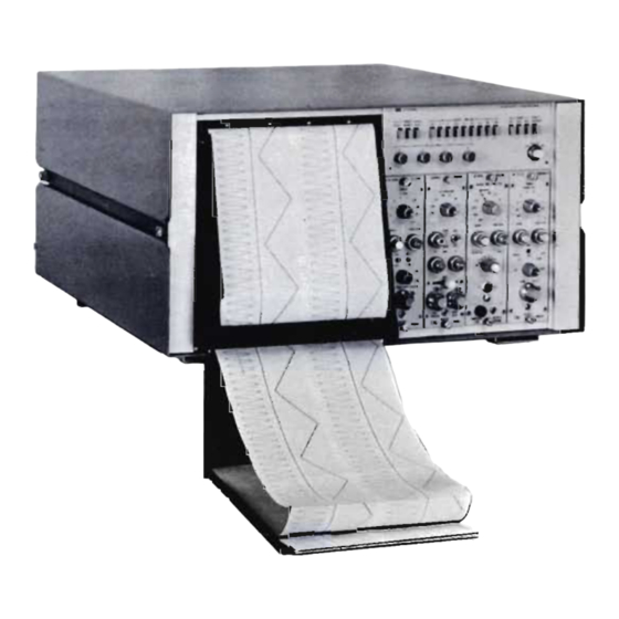
HP 7414A Operating And Service Manual (113 pages)
THERMAL-TIP RECORDER
Brand:
HP
| Category:
Recording Equipment
| Size: 10.28 MB
Table of Contents
Table of Contents
7
Applications and Specifications
10
Four-Channel Recorder
10
Section I, General Information
10
Model 7414A Recording System
11
Accessories
13
Section II, Installation
14
Initial Inspection
14
Mechanical Check
14
Performance Tests
14
Damage Claims
14
Storage
14
Installation
14
Preamplifier Installation
14
Power Connections
14
Remote Control and Marker Connections
17
Signal Connections
17
Tape System Connections
17
Section III, Operation
19
Galvanometer Position Feedback
22
Section IV, Principles of Operation
22
Stylus Linkage
22
Galvanometer Damping
23
Heat Control Circuit
23
Power Control Circuits
23
Preamplifier Power Supply Circuits
24
Oscillator
24
Recorder Signal Circuits
25
Galvanometer Position Feedback Circuit
26
Galvanometer Damping
26
Chart Drive
28
Chart Motor
28
Speed Control
28
Chart Drive Gears
28
Paper Feed
31
Recorder Power Supply and Regulator Circuits
31
Recorder DC Power Supplies
31
Paper Feed Path
31
Recorder Power Supply and Regulator Circuits, Simplified Circuit
32
Regulator/Oscillator
33
Marker Circuits
33
440 Hz Oscillator
34
2400 Hz Oscillator Circuit
34
Section V, Maintenance
35
Test Equipment and Lubricants
35
Performance Checks
35
Recommended Test Equipment
35
Variable Line Voltage
36
Preventive Maintenance
36
Operational Checks and Inspection
36
Lubricants and Solvents Required
36
Test and Adjustment Points
37
Electrical Performance Checks and Adjustments
39
Cleaning
43
Lubrication
43
Electrical Checks
44
Adjustments and Minor Repairs
44
Paper Drive Adjustments
44
Test Cable, Plug and Fixtures
45
Driver Amplifier and Regulator/Oscillator Test
46
Stylus Adjustments
46
Regulator/Oscillator Board Test Points
47
Driver Amplifier Board Test Points
48
Paper Brake Felt Cover Removal and Replacement
50
Stylus Adjustments
52
Corrective Maintenance
52
Galvanometer Removal and Replacement
53
Drive Unit Removal and Replacement
53
Channel Time Synchronization Adjustment
53
Gearbox Removal
53
Paper Table Removal
53
Stylus Removal and Replacement
54
Drive Unit Removal
55
Paper Table Disassembly for Drive
57
Gearbox Removal and Overhaul
57
Drive Roller and Table Link Removal (Part 1)
59
Drive Roller and Table Link Removal (Part 2)
60
Gearbox Inspection and Solenoid Adjustment
62
Gearbox Shaft End Play Adjustment
66
Spring Clutch Lubrication (Primary Shaft)
67
Overriding Clutch Lubrication (Secondary Shaft)
68
Gearbox Input Chain Tension Adjustment
69
Solenoid Adjustment
70
Marker Assembly Maintenance ·5-34
70
Marker Assembly Adjustment and Removal
70
Section VI, Recplaceable Parts
71
Reference Designations
71
Ordering Information
72
Locations
72
Driver Amplifier
73
Replaceable Parts
73
Table
77
Code List of Manufacturers
88
Control Panel A2 (07754-60240) Subassemblies
89
Control Panel A2 Schematic Diagram
92
Control Switch Board A2A
93
Heat Potentiometer Board A2A2
93
Preamplifier Power Supply Board A2A3
94
Power Supply A3
96
Power Supply A3, Schematic Diagram
97
Schematic Diagram
99
Driver Amplifier
100
Component Location
103
Regulator/Oscillator A8 (60 Hz, 07754-60180)
103
Drive Unit AI0 (07754-60250) Subassemblies, Parts Location Diagram
104
Parts Location Diagram
106
Parts Location Diagram
107
Related Products
HP 7750
HP 7751
HP 7700 Series
HP 70907A
HP 70907B
HP 3PAR StoreServ 7450 2-node
HP Vectra VEi 7 466/66
HP 747i/100
HP 744rt/165L
HP EliteBook 745 G6
HP Categories
Desktop
Laptop
Server
Monitor
Switch
More HP Manuals