beautypg.com
Manuals
Brands
Emerson Manuals
Welding System
Branson 2000 Series
Emerson Branson 2000 Series Manuals
Manuals and User Guides for Emerson Branson 2000 Series. We have
1
Emerson Branson 2000 Series manual available for free PDF download: Instruction Manual
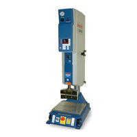
Emerson Branson 2000 Series Instruction Manual (135 pages)
Integrated Welder
Brand:
Emerson
| Category:
Welding System
| Size: 10.44 MB
Table of Contents
Table of Contents
4
Chapter 1: Safety and Support
10
Safety Requirements and Warnings
11
Figure 1.1 Safety Labels on the 2000IW/IW+ Integrated Welder
12
Figure 1.2 Safety Label on Left Door of the 2000IW/IW+ Integrated Welder
12
General Precautions
13
Warranty Statement, Disclaimer
15
Table 1.1 Warranty Period
15
How to Contact Branson
17
Returning Equipment for Repair
18
Table 1.2 Branson Contact
19
Obtaining Replacement Parts
21
Chapter 2:The 2000IW/IW+ Welder
22
Models Covered
23
Overview of These Models
24
Figure 2.1 2000IW/IW+ Series Integrated Welder
24
Compatibility with Branson Products
27
Features
28
Front Panel Controls
29
Figure 2.2 Front Panel Controls, IW
29
Table 2.1 Front Panel Controls IW
29
Figure 2.3 Front Panel Displays, IW
31
Table 2.2 Front Panel Displays, IW
31
Figure 2.4 Front Panel Displays, IW
33
Table 2.3 Front Panel Displays, IW
33
Rear Panel
36
Figure 2.5 Rear Panel
36
Table 2.4 Rear Panel
36
System Inputs/Outputs
38
Figure 2.6 Base, Showing START SWITCHES and Base Cable
38
Glossary of Terms
40
Chapter 3:Delivery And Handling
42
Shipping and Handling
43
Receiving
44
Table 3.2 Inspection Upon Delivery
44
Unpacking
45
Table 3.3 When Unpacking the Integrated Welder, Take the Following Steps
45
Returning Equipment
46
Chapter 4: Installation and Setup
48
About Installation
49
Handling and Unpacking
50
Figure 4.1 Unpacking the Stand (2000IW/IW+ on a Base); Right-Side View of Stand
50
Figure 4.2 Unpacking the Stand (2000IW/IW+ on a Hub); Hub Shown Separately
51
Figure 4.3 Ultrasonic Converter (J-Type for Stand Use) and Booster
52
Take Inventory of Small Parts
53
Table 4.1 Small Parts Included (=X) with IW/IW+ Integrated Welder
53
Table 4.2 List of Cables
53
Installation Requirements
54
Figure 4.4 2000IW/IW+ Integrated Welder Dimensional Drawing
55
Table 4.3 Environmental Specifications
55
Table 4.4 Input Power Requirements
56
Figure 4.5 Hooking up the Air Line
57
Installation Steps
58
Figure 4.6 Base Mounting Centers
59
Figure 4.7 Mounting Bolt Pattern for the Hub (for Stand on Hub)
60
Figure 4.8 Start Switch Connection Codes
61
Figure 4.9 Input/Output Signals, IW/IW
63
Figure 4.10Operating Cycle Timing Table, 2000IW
64
Figure 4.11Operating Cycle Timing Table, 2000IW
64
Figure 4.12Moving Jumpers
65
Figure 4.13International Harmonized Line Cord Color Code
65
Figure 4.14Type 1 DIP Switch Marked "OPEN" on Top of Switch, Default Settings
66
Table 4.5 Options for Setting the Type 1 Switch Select Block
66
Figure 4.15Type 2 DIP Switch Marked "ON" on Face of Switch, Default Settings
67
Table 4.6 Options for Setting the Type 2 Switch Select Block
67
Accessory Input/Output Option
69
Figure 4.16Accessory Input/Output Connector Pinout
69
Guards and Safety Equipment
70
Figure 4.17Integrated Welder Emergency Stop Button
70
Assemble the Acoustic Stack
71
Table 4.7 Assemble the Acoustic Stack
71
Figure 4.18Assembling the 20Khz Acoustic Stack, Rectangular Horn
72
Figure 4.19Assembling the 20Khz Acoustic Stack, Cylindrical Horn
72
Table 4.8 Tools
72
Figure 4.20Connecting Tip to Horn
73
Table 4.9 Stud Torque Values
73
Table 4.10 Tip to Horn Torque Value
73
Installing the Ultrasonic Stack in the Integrated Welder
74
Figure 4.21Installing a 20Khz Stack in a Branson Welder
74
Figure 4.22Mounting Circles on Base
75
4.10 Adjusting Welder Height and Aligning the Horn
76
4.11 Adjusting the Mechanical Stop
77
Figure 4.23Adjusting the Mechanical Stop
77
Figure 4.24DIP Switch Location
78
4.12 Testing the Installation
81
Figure 4.25Normal Front Panel Display after Power -Up, IW (Left), IW+ (Right)
81
4.13 Still Need Help? or Parts? Have Questions
82
Chapter 5 5:Technical Specifications
85
Table 5.2 Electrical Requirements
85
Figure 5.1 CJ 20 Converter
87
Table 5.3 2000IW/IW+ Boosters
87
Table 5.4 Other Items Used with the 2000IW/IW
88
Chapter 6:Operation
90
Weld Modes
91
Table 6.1 Parameter Functions
92
Table 6.2 Limit Function
93
Table 6.3 Pretrigger Settings
93
Figure 6.1 Time Mode, IW+ Only
95
Table 6.4 Time Mode Parameters, IW+ Only
95
Table 6.5 Collapse Distance Mode Parameters, IW+ Only
97
Figure 6.2 Absolute Distance Mode, IW+ Only
99
Table 6.6 Absolute Distance Mode Parameters, IW+ Only
99
Setting Weld Cycle Parameters
101
Table 6.7 Weld Parameter Values IW+ Only
101
Table 6.8 Recalling Pre-Defined Parameter Values
102
Controlling the Front Panel Display
104
Setup Procedure
105
Figure 6.3 Setup and Operation in Time Mode
107
Figure 6.4 Setup and Operation in Collapse /Absolute Distance Modes
108
Weld Cycle State Displays and Alarms
109
Table 6.9 2000IW State Displays
109
Table 6.10 222IW+ State
110
Table 6.11 Error Codes
112
Resetting the System
116
Ultrasonic Test
117
Horn down
118
Converter Cooling
119
Chapter 7:Maintenance
120
IW/IW+ Preventive Maintenance
121
Table 7.1 Stack Reconditioning Procedure
122
Figure 7.1 Reconditioning Stack Surfaces
123
Figure 7.2 Disassembly of Air Filter Components
123
Parts Lists
125
Table 7.2 Replacement Parts
125
Circuits
126
Figure 7.3 2000 IW/IW+ Interconnect Schematic
126
Troubleshooting
127
Figure 7.4 Manual Adjustment Procedure Flowchart
128
Related Products
Emerson Bristol ControlWave ExpressPAC
Emerson Bristol ControlWave Express
Emerson Bristol ControlWave LP
Emerson Bristol ControlWave PAC
Emerson Bristol ControlWave EFM
Emerson Branson LPX
Emerson Bettis GVO LP DA
Emerson Bettis SMART EHO G Series
Emerson BBCF370
Emerson TARTARINI BM5A
Emerson Categories
Controller
Control Unit
Transmitter
Measuring Instruments
Fan
More Emerson Manuals