Dell PowerEdge M1000e Configuration Manual
Hide thumbs
Also See for PowerEdge M1000e:
- Configuration manual (232 pages) ,
- Getting started (224 pages) ,
- Reference manual (135 pages)
Table of Contents
Quick Links
Table of Contents

Related Manuals for Dell PowerEdge M1000e


Summary of Contents for Dell PowerEdge M1000e
- Page 1 Dell™ PowerEdge™ M1000e Systems Configuration Guide...
- Page 3 Dell™ PowerEdge™ M1000e Systems Configuration Guide...
- Page 4 Other trademarks and trade names may be used in this document to refer to either the entities claiming the marks and names or their products. Dell Inc. disclaims any proprietary interest in trademarks and trade names other than its own.
-
Page 5: Table Of Contents
Contents About Your System ....System Overview ..... System Control Panel Features . - Page 6 Configuring the Optional iKVM Switch Module ..Enabling iKVM Access to the Dell CMC Console ..... . .
-
Page 7: Contents
Pass-through Modules ....Ethernet Pass-through Module ..Fibre Channel Pass-through Module ..Contents... - Page 8 Contents...
-
Page 9: About Your System
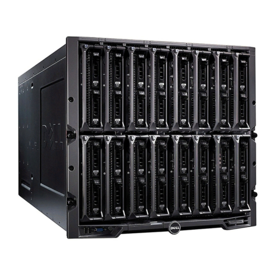
About Your System System Overview Your system can include up to 16 half-height blades (server modules), eight full-height blades, or a mixture of the two blade types (see Figure 1-1, Figure 1-2, and Figure 1-3). To function as a system, a blade is inserted into a enclosure (chassis) that supports power supplies, fan modules, a Chassis Management Controller (CMC) module, and at least one I/O module for external network connectivity. - Page 10 Figure 1-1. Blade Numbering – Half-Height Blades Configuration Guide...
- Page 11 Figure 1-2. Blade Numbering - Full Height Blades Figure 1-3. Blade Numbering - Mixed Full-Height and Half-Height Blades Configuration Guide...
-
Page 12: System Control Panel Features
System Control Panel Features Figure 1-4 shows the control panel features on the M1000e enclosure front panel. Figure 1-4. Control Panel Features USB port (mouse only) USB port (keyboard only) video connector system power button system power indicator NOTE: The USB and video ports are functional only if an optional iKVM module is installed. -
Page 13: Lcd Module
LCD Module The LCD module provides an initial configuration/deployment wizard, as well as access to infrastructure and blade information and error reporting. See Figure 1-5. Figure 1-5. LCD Module LCD screen scroll buttons (4) selection ("check") button Configuration Guide... -
Page 14: Lcd Module Menus
LCD Module Menus Main Menu The Main Menu options include links to the Server Menu, the Enclosure Menu, and the LCD Setup Menu. LCD Setup Menu You can change the default language and startup screen for the LCD menu screens using this menu. Server Menu From the Server Menu dialog box, you can highlight each blade in the enclosure using the arrow keys, and view its status. -
Page 15: Back-Panel Features
Back-Panel Features The back of the M1000e enclosure supports six I/O modules, one or two CMC modules, an optional iKVM module, nine fan modules, and six power supply modules. Figure 1-6 shows a fully configured enclosure. Figure 1-6. Back-Panel Features fan modules (9) primary CMC module I/O modules (6) - Page 16 Figure 1-7. Front Panel Features - PowerEdge M600 and M605 blade handle release button hard drives (2) blade status/identification indicator USB connectors (2) blade power button blade power indicator Configuration Guide...
- Page 17 Figure 1-8. Front Panel Features - PowerEdge M905 and M805 blade handle release button hard drives (2) blade status/identification indicator USB connectors (3) blade power button blade power indicator Configuration Guide...
-
Page 18: Cmc Module
CMC Module Figure 1-9. CMC Module Features Ethernet connector Gb1 Ethernet connector STK (used for daisy-chaining CMCs in separate enclosures) link indicator (2) activity indicator (2) DB-9 serial connector for local optional secondary CMC (CMC 2) configuration primary CMC (CMC 1) amber fault indicator blue status/identification indicator power indicator... -
Page 19: Cmc Daisy Chaining (Enclosure Stacking)
CMC Daisy Chaining (Enclosure Stacking) CMC daisy chaining can be utilized to minimize the number of network connections required for chassis (enclosure) management, such that only one or two network connections (depending on whether or not redundant CMCs are installled) are needed for up to four M1000e enclosures. Cabling Guidelines Follow these guidelines to daisy chain CMC modules from enclosure to enclosure:... - Page 20 Figure 1-10. CMC Daisy-Chaining – Enclosure With Redundant CMC Modules Management network segment CMC1 – cable from connector Gb1 to network CMC2 – cable from connector Gb1 to network Configuration Guide...
-
Page 21: Ikvm Switch Module
NOTE: The iKVM USB ports do not support storage devices. – RJ-45 ACI port for tiering with Dell and Avocent analog KVM and KVM over IP switches with ARI ports. NOTE: Although the ACI port is an RJ-45 connector and uses Cat5 (or better) cabling, it is not an Ethernet network interface port. - Page 22 Figure 1-11 shows the external features of the iKVM module. Figure 1-11. Avocent iKVM Switch Module identification indicator status indicator ACI port for tiering connection USB connectors (2) for keyboard only and mouse video connector NOTICE: Do not connect the ACI port to a LAN device such as a network hub.
-
Page 23: Initial System Configuration
Initial System Configuration Before You Begin Power Requirements NOTICE: The enclosure power supplies must be connected to a Type B or permanently-connected PDU, not directly to an electrical outlet. The power supplies require a 200–240 V power source. Network Information If your network uses static addressing, you will need the IP address, subnet mask, and gateway to configure the CMC and other modules in the enclosure. -
Page 24: Configuring The Cmc
4 Press the power button on the enclosure control panel. See Figure 1-4. 5 Configure the CMC network settings. The LCD Configuration Wizard allows you to quickly configure the CMC and iDRAC management interfaces and on the network, so you can then manage the enclosure remotely. - Page 25 Configuring the CMC Network Settings Using the LCD Configuration Wizard When you first start up your system, the screen on the LCD module will direct you to configure the CMC network settings. NOTE: The option to configure the server using the LCD Configuration Wizard is only available until the CMC is connected to the network or the default password is changed.
- Page 26 4 If desired, configure the iDRAC network setting for DHCP mode. NOTE: You cannot set a static IP address for the iDRAC using the LCD Configuration Wizard. See "Configuring iDRAC Networking Using the Web- Based Interface" on page 27. 5 Review the settings on the Network Summary screen. –...
-
Page 27: Logging In To The Cmc Using The Web-Based Interface
3 Configure the CMC network settings: – To set a static IP address, type setniccfg -sand press . Use the appropriate settings for your network. To configure the CMC to obtain an IP address using DHCP , type –... -
Page 28: Adding And Managing Cmc Users
NOTE: For added security, Dell strongly recommends that you change the default password of the root (User 1) account. The root account is the default administrative account that ships with the CMC. To change the default password for the root account, click User ID 1 to open the User Configuration page. -
Page 29: Configuring Idrac Networking Using The Web-Based Interface
3 Click the Network/Security tab, and then click the Users sub-tab. The Users page appears, listing each user’s user ID, login state, user name, and CMC privilege, including those of the root user. User IDs available for configuration will have no user information displayed. 4 Click an available user ID number. -
Page 30: Setting The First Boot Device For Servers
5 Enable or disable IPMI over LAN by checking the or unchecking the checkbox next to the server beneath the Enable IPMI over LAN heading. 6 Enable or disable DHCP for the iDRAC by checking or unchecking the checkbox next to the server under the DHCP Enabled heading. 7 If DHCP is disabled, enter the static IP address, netmask, and default gateway for the iDRAC. -
Page 31: Installing Or Updating The Cmc Firmware
NOTE: To perform power management actions, you must have Chassis Control Administrator privileges. 1 Log in to the CMC Web-based interface. 2 Select Chassis in the system tree. 3 Click the Power Management tab. The Power Budget Status page displays. 4 Click the Configuration sub-tab. - Page 32 CMC in the left slot as primary. Downloading the CMC Firmware Before beginning the firmware update, download the latest firmware version from the Dell Support website, and save it to your local system. The following software components are included with your CMC firmware package: •...
-
Page 33: Configuring The Optional Ikvm Switch Module
2 Type: racadm fwupdate -g -u -a-d -m -
Page 34: Tiering The Avocent Ikvm Switch From An Analog Kvm Switch
Tiering the Avocent iKVM Switch From an Analog KVM Switch The Avocent iKVM switch can be tiered from analog KVM switches such as the Dell 2160AS and 180AS, as well as many Avocent analog KVM switches. Many switches may be tiered without the need for a Server Interface Pod (SIP) (see Table 2-2). -
Page 35: Tiering The Avocent Ikvm Switch From A Digital Kvm Switch
The iKVM module may also be tiered from a digital KVM switch such as the Dell 2161DS-2 or 4161DS, or a supported Avocent digital KVM switch. Many switches may be tiered without the need for a SIP (see Table 2-3). -
Page 36: Viewing And Selecting Servers
Avocent DSR 1024 Avocent USB SIP (DSRIQ-USB) required with Cat 5 cable To tier the iKVM module from a Dell 2161DS, 180AS, or 2160AS console switch: • If the switch does not require a SIP to connect to the iKVM (see Table 2-3), connect a Cat5 (or newer) cable to the RJ-45 ACI port on the iKVM module. -
Page 37
To access the dialog box: Main Press
to launch the OSCAR interface. The dialog box Main appears. If a password has been assigned, the Password dialog box appears. Type your password and click OK. The dialog box appears. Main Resynchronizing the Server List at the Remote Client Workstation Once the iKVM module is connected, the blades appear in OSCAR. -
Page 38: Flexaddress
If you purchase FlexAddress at a later date, you must install the SD feature card using the instructions in the CMC Secure Digital (SD) Card Technical Specification document. See support.dell.com for this document. For complete information on using the FlexAddress feature, click the Help link in the CMC Web interface, or review the "Using FlexAddress"... -
Page 39: Configuring The I/O Modules
Configuring the I/O Modules Overview The M1000e enclosure supports three redundant I/O fabrics, selectable between combinations of Ethernet and Fibre Channel modules. (Additional fabrics including Infiniband will be supported in the future.) You can install up to six hot-swappable I/O modules in the enclosure, including Fibre Channel switches, Fibre Channel pass-throughs, Ethernet switches, and Ethernet pass- through modules. - Page 40 Fabric A Fabric A is a redundant Gb Ethernet fabric, supporting I/O module slots A1 and A2. The integrated Ethernet controllers in each blade dictate Fabric A as an Ethernet-only fabric. NOTICE: Modules designed for Fabric B or Fabric C cannot be installed in slots A1 or A2.
-
Page 41: Before You Begin
Before You Begin Network Information You can configure your I/O switch modules using the CMC, as outlined in "Configuring a Switch Module Network Ethernet Port Using the Web-Based Interface" on page 39 (the default IP address for the CMC is 192.168.0.120), through the CMC CLI via serial console redirection, direct access to the I/O module’s serial port (if supported), or using the I/O module’s default IP address (if supported). -
Page 42: Cisco Sfs M7000E Infiniband Switch Module
4 Configure the switch for integration into your network. – Select DHCP Mode Enabled if your network uses a DHCP server to assign IP addresses. – If your network uses static IP addressing, enter an IP address, subnet mask and gateway. 5 When you have finished, click Apply. - Page 43 Figure 3-2. Cisco SFS M7000e Infiniband Switch Module Features Infiniband ports (8) port status indicator (8) diagnostic status indicator power indicator Configuration Guide...
-
Page 44: Powerconnect M6220 Ethernet Switch Module
PowerConnect M6220 Ethernet Switch Module The PowerConnect M6220 Ethernet switch module includes four external 10/100/1000 Mbps Ethernet connectors and one USB type A form factor serial connector. See Figure 3-3. Figure 3-3. PowerConnect M6220 Ethernet Switch Module Features optional module (2) (dual 10 Gb standard 10/100/1000 Mb Ethernet Ethernet uplink module shown) connectors (4) -
Page 45: Cisco Ethernet Switch
Two option bays support the following three module options: • A resilient stacking module with 2 x 24 Gb stacking ports • A 10 Gb Ethernet module with two 10 Gb optical XFP connectors • 10 Gb Ethernet module with two copper CX4 uplinks Cisco Ethernet Switch Your system supports three Cisco Catalyst Blade Switch (CBS) versions: •... - Page 46 Figure 3-4. Cisco Ethernet Switch Module Features stacking port connectors (not 10/100/1000 Mb Ethernet enabled in CBS 3032) connectors (4) option bays (2) Cisco status indicators mode button console port for switch management power indicator status/identification indicator For additional information about the Cisco CBS Ethernet switch modules, see the documentation that shipped with the module.
-
Page 47: Brocade M4424 San I/O Module
Brocade M4424 SAN I/O Module The Brocade M4424 SAN I/O module includes eight external autosensing Fibre Channel ports (four ports are enabled in the standard configuration and four additional ports may be enabled as an optional upgrade), 16 internal ports, and one serial port with an RJ-45 connector. The external Fibre Channel ports operate at 1 Gb/sec, 2 Gb/sec, or 4 Gb/sec. - Page 48 Figure 3-5. Brocade M4424 SAN I/O Module Features Fibre Channel port (8) Fibre Channel port status indicator (8) Fibre Channel port speed serial port (RJ-45 connector) indicator (8) module status indicator power indicator status/identification indicator Configuration Guide...
- Page 49 Pass-through Modules Ethernet Pass-through Module The Ethernet pass-through module supports 10/100/1000 Mb connections, and provides a direct connection between the optional internal Ethernet mezzanine card in the blade or the integrated LOMs in the blade, and an external Ethernet device (see Figure 3-6). The Ethernet pass-through modules are hot-pluggable and may be installed in any of the three fabrics.
- Page 50 Figure 3-6. Ethernet Pass-through Module Features activity indicator (16) link indicator (16) RJ45 Ethernet connector (16) power indicator status/identification indicator NOTE: Connectors on the Ethernet pass-through module correspond directly to the blade number. For example, blade 5 is connected to port 5 on the Ethernet pass- through module.
- Page 51 Fibre Channel Pass-through Module The Fibre Channel pass-through module provides a bypass connection between a Fibre Channel mezzanine card in the blade and optical transceivers for direct connection into a Fibre Channel switch or a storage array (see Figure 3-7). The 16 pass-through ports on this module can negotiate speeds of 1-, 2-, or 4-Gbps.
- Page 52 Figure 3-7. Fibre Channel Pass-through Module Features SFP Fibre Channel connector (16) Fibre Channel green/amber indicators (two per port) power indicator status/identification indicator Configuration Guide...
- Page 54 ww w.d el l .c o m | s up p or t . de l l. c o m...