Quick Links
See also:
Instruction Manual
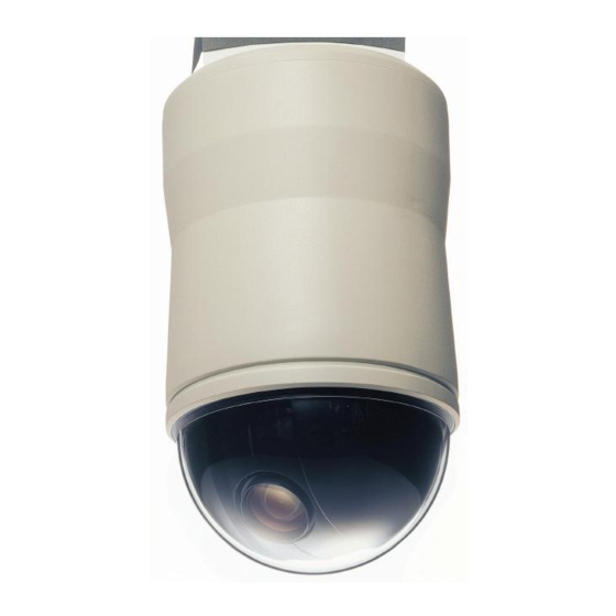
SERVICE MANUAL
Dome type camera
CONTENTS
SPECIFICATIONS ...................................2
1. DISASSEMBLY ....................................3
2. POWER BOARD ADJUSTMENT ........4
3. CAMERA PART ....................................6
4. TROUBLESHOOTING GUIDE ...........10
5. PARTS LIST .......................................15
CIRCUIT DIAGRAM &
PRINTED WIRING BOARDS ................ C1
The components designated by a symbol ( ! ) in this schematic diagram designates components whose value are of
special significance to product safety. Should any component designated by a symbol need to be replaced, use only the
part designated in the Parts List. Do not deviate from the resistance, wattage, and voltage ratings shown.
NOTE : 1. Parts order must contain model number, part number, and description.
2. Substitute parts may be supplied as the service parts.
3. N. S. P. : Not available as service parts.
Design and specification are subject to change without notice.
L5AE4/XE, US
PRODUCT SAFETY NOTICE
FILE NO.
VCC-9400P
(Product Code : 117 119 00)
(Europe)
VCC-9400
(Product Code : 117 119 01)
(U.S.A.)
(Canada)
(Korea)
(Taiwan)
Please see other materials with Reference number
given in table below.
Materials
Model No.
VCC-9300
MECHANISM
VCC-9300P
SERVICE
VCC-9400P
TECHNICAL
VCC-9400
INFORMATION
REFERENCE No. SM5310480
Reference No.
MM5310481

Related Manuals for Sanyo VCC-9400P


Summary of Contents for Sanyo VCC-9400P
-
Page 1: Table Of Contents
FILE NO. SERVICE MANUAL Dome type camera VCC-9400P (Product Code : 117 119 00) (Europe) VCC-9400 (Product Code : 117 119 01) (U.S.A.) (Canada) (Korea) (Taiwan) CONTENTS SPECIFICATIONS ........2 1. DISASSEMBLY ........3 Please see other materials with Reference number 2. POWER BOARD ADJUSTMENT ..4 given in table below. -
Page 2: Specifications
Backlight compensation : Centrweighted average metering/multi-spot evaluative metering/multi-spot metering Day/Night : AUTO / COLOR / B/W settings available Electronic shutter : • Fast shutter speed (SHORT) mode: 1/50 (VCC-9400P), 1/60 (VCC-9400), 1/100 (VCC-9400), 1/120 (VCC-9400P), 1/250, 1/500, 1/1000, 1/2000, 1/4000, 1/10000 •... -
Page 3: Disassembly
1. DISASSEMBLY Please refer to BASIC SERVICE TECHNICAL INFORMATION (MM5310481) of a separate volume for details. BASE unit MAIN unit SY-1 board POWER board ROTATION unit CAMERA unit CASE MAIN board CAMERA COVER CLEAR DOME INNER COVER – 3 –... -
Page 4: Power Board Adjustment
2. POWER BOARD ADJUSTMENT 2-1. Disassembly 1. A camera unit and a base unit 3. A rotation unit is pulled out. 2. The attachment screw of a are separated. A power supply is rotation unit is removed. surely shut off. 4. - Page 5 2-3. ADJUSTMENT 2-3-1. Voltage Adjustment Adjustment location: VR301, VR302 Measuring location: TP305, TP306 Measuring equipment: Digital multi meter Subject: No designation Adjusting method: 1. A connector CN302 is removed and voltage is adjusted. 2. Adjust with VR301 to 9.0 V . 3.
-
Page 6: Camera Part
3. CAMERA PART 3-1. DISASSEMBLY AND BOARD LOCATION Cover left CA-2 board CA-1 board Chassis Cover right CA-3 board CA-2 board VR203 VR202 TP221 CT202 TP202 TP203 CA-1 board CT252 CT201 TP201 CA-3 board TP200 CA-2 board (Side B) – 6 –... - Page 7 3-2-3. TABLE FOR SERVICING TOOLS 3-2. ADJUSTMENT 3-2-1. ADJUSTMENT CONDITION Ref. No. Name Part code 1. Use the 5,100K viewer for the subject. Color viewer VJ8-0007 2. Set the trigger signal of oscilloscope to VIDEO OUT, and Gray scale chart VJ8-0010 apply H sync unless specified.
- Page 8 Subject: Color bar chart 1. Select POS2 in the adjustment display, and project the color 3-2-7. Frequency Adjustment (INT) (VCC-9400P ONLY) bar chart at the field angle of below figure. Adjustment location: CT252, CT202 (CA-2) 2. Select the R and B in the adjustment display. Adjust by oper- ating ←...
- Page 9 45 µsec 100% 3-2-11. CCD White Point Defect Detect Adjustment Measuring location: VIDEO OUT Measuring equipment: Monitor display Adjustment method: 1. Shield light with a lens cap to provide dark condition. 2. Set the camera mode, and click the “AUTO” at the WDD on the adjustment software.
-
Page 10: Troubleshooting Guide
4. TROUBLESHOOTING GUIDE 4-1. Judgment of fault The check of a condition. Related to the image. Refer to the 4-2.check of image. Related to the control. Refer to the 4-3.check of control. Related to the mechanism. Refer to the 4-4.check of mechanism. –... - Page 11 4-2. CHECK OF IMAGE FAULT DETAILED CONTENTS CONTENTS OF A CHECK The confirmation of the AC power supply. An image doesn't come out. An initialization movement isn't done, either. The microswitch of a base unit is checked. It can be operated. The harness of an image system is checked.
- Page 12 4-3. CHECK OF CONTROL FAULT DETAILED CONTENTS CONTENTS OF A CHECK Initialization operation is not A BASE unit or a MAIN unit is exchanged and carried out. checked. Initialization operation The gap check of Sensor IC and a magnet. performs repeatedly. A MAIN board is exchanged and checked.
- Page 13 4-4. CHECK OF MECHANISM FAULT DETAILED CONTENTS CONTENTS OF A CHECK A motor is exchanged and checked. PAN and TILT operation are not carried out. A MAIN board is exchanged and checked. It does not operate smoothly. It checks whether bearing etc. is heavy. An allophone carries out at the time of It checks whether harness is caught in the rotation.
- Page 14 4-5. A BASE UNIT AND A MAIN UNIT ARE EX- CHANGED AND CHECKED It works after a power supply is surely turned off when it is connected with the extension cable (VHJ-0154). A circuit board is sometimes damaged when it works in power supply on.
-
Page 15: Parts List
645 060 8087 ALARM IN CABLE ASS’Y 645 060 9381 LABEL,VCC-9400 ONLY (N.S.P.) 645 060 9565 PACKING BOX 645 060 9374 LABEL,VCC-9400P ONLY (N.S.P.) 645 060 9268 BUFFER A 645 060 9404 INSTROCTIONS,VCC-9400 ONLY 645 060 9275 645 060 9398... - Page 16 LOCATION PARTS NO. DESCRIPTION LOCATION PARTS NO. DESCRIPTION 645 061 7454 MAIN BOARD ASS’Y(NEW) CABINET AND CHASSIS PARTS 1 645 060 8131 SENSOR BOARD ASS’Y(OLD) 645 060 7394 CAMERA COVER 645 061 7461 SENSOR BOARD ASS’Y(NEW) 645 060 9558 INNER COVER 645 060 7790 RH SW/W SCR.
- Page 17 LOCATION PARTS NO. DESCRIPTION CABINET AND CHASSIS PARTS 2 645 060 7370 MAIN FRAME 645 060 7387 T-HOLDER 645 060 7394 CAMERA COVER 645 060 7424 FRAME A 645 060 7431 FRAME B 645 060 7448 CAMERA BASE 645 060 7462 SUPPORTER 645 060 7509 SHIM...
- Page 18 FLEXIBLE FLAT CABLE 645 060 7653 STANDARD LABEL VCC-9400 ONLY (N.S.P.) 645 060 7813 RH SCR. 2.6*3MM 645 060 7646 STANDARD LABEL VCC-9400P ONLY (N.S.P.) 645 060 7820 BH SCR. 2*4MM 645 060 7745 MAGNET BASE 645 060 7837 FH SCR. 2*12MM...
- Page 19 RELAY/I-O CABLE ASS’Y 645 060 7653 STANDARD LABEL VCC-9400 ONLY (N.S.P.) 645 060 8056 DC24V POWER CABLE ASS’Y 645 060 7646 STANDARD LABEL VCC-9400P ONLY (N.S.P.) 645 060 8094 COMPOUND CABLE ASS’Y 645 060 7660 FERRITE CORE 613 198 6060 COMPL PWB,SY-1(SY- BOARD ASS’Y)
- Page 20 COMPL,MECHA DN CABINET AND CHASSIS PARTS 6 613 199 0807 COMPL PWB,CA-1 6005 613 199 2917 SPACER 613 199 0760 COMPL PWB,CA-2,VCC-9400P ONLY 6010 613 199 2900 CHASSIS 613 199 0784 COMPL PWB,CA-2,VCC-9400 ONLY 6015 613 197 2902 COVER LEFT...
- Page 21 ELECTRICAL PARTS LOCATION PARTS NO. DESCRIPTION LOCATION PARTS NO. DESCRIPTION C121 645 060 8766 CC CAP. GRM188F11H103Z 0.01UF/50V MAIN BOARD ASS’Y C122 645 060 8766 CC CAP. GRM188F11H103Z 0.01UF/50V 645 060 8100 MAIN BOARD ASS’Y(OLD) C123 645 060 8766 CC CAP. GRM188F11H103Z 0.01UF/50V 645 061 7454 MAIN BOARD ASS’Y(NEW) C124...
- Page 22 LOCATION PARTS NO. DESCRIPTION LOCATION PARTS NO. DESCRIPTION R125 645 060 8292 RES. RK73Z1JTD 0OHM 1/16W 0 (DIODES) R126 645 060 8513 RES. RK73H1JTD 1MF 1/16W 1M D301 645 060 9039 DIODE RB161L-40 R127 645 060 8391 RES. RK73H1JTD 3.3KF 1/16W 3.3K D302 645 060 9039 DIODE RB161L-40...
- Page 23 LOCATION PARTS NO. DESCRIPTION LOCATION PARTS NO. DESCRIPTION C0205 403 155 1807 CERAMIC 0.01U K 25V COMPL PWB,SY-1(SY-1 BOARD ASS’Y) C0206 403 175 0606 ELECT 100U M 6.3V 613 198 6060 COMPL PWB,SY-1 C0207 403 155 1807 CERAMIC 0.01U K 25V C0210 403 157 6800 CERAMIC...
- Page 24 LOCATION PARTS NO. DESCRIPTION LOCATION PARTS NO. DESCRIPTION R0230 401 105 5400 MT-GLAZE 47K JA 1/16W COMPL PWB,CA-1 R0231 401 105 0603 MT-GLAZE 10K JA 1/16W 613 199 0807 COMPL PWB,CA-1 R0232 401 105 0603 MT-GLAZE 10K JA 1/16W R0234 401 105 0603 MT-GLAZE 10K JA 1/16W...
- Page 25 403 164 0204 CERAMIC 0.1U Z 25V Q2001 405 135 9407 TR DTA114EUA C2005 403 150 2106 NP-ELECT 4.7U M 25V,VCC-9400P ONLY Q2003 405 133 8907 TR DTC114EUA C2006 403 311 3409 CERAMIC 0.01U K 16V,VCC-9400P ONLY Q2004 405 135 9407...
- Page 26 401 225 8701 MT-GLAZE 120K JA 1/16W C2089 403 305 0001 TA-SOLID 10U M 10V R2010 401 224 9808 MT-GLAZE 220K JA 1/16W,VCC-9400P ONLY C2090 403 346 2309 CERAMIC 0.1U K 10V R2010 401 226 1503 MT-GLAZE 0.000 ZA 1/16W,VCC-9400 ONLY...
- Page 27 401 226 1503 MT-GLAZE 0.000 ZA 1/16W R2179 401 226 1503 MT-GLAZE 0.000 ZA 1/16W R2501 401 224 9402 MT-GLAZE 1.0M JA 1/16W,VCC-9400P ONLY R2183 401 226 1503 MT-GLAZE 0.000 ZA 1/16W R2502 401 226 1503 MT-GLAZE 0.000 ZA 1/16W...
- Page 28 LOCATION PARTS NO. DESCRIPTION LOCATION PARTS NO. DESCRIPTION R3102 401 105 1600 MT-GLAZE 15K JA 1/16W COMPL PWB,CA-3 R3103 401 105 1105 MT-GLAZE 12K JA 1/16W 613 199 0814 COMPL PWB,CA-3 R3104 401 105 7909 MT-GLAZE 0.000 ZA 1/16W R3105 401 105 0702 MT-GLAZE 100K JA 1/16W (SEMICONDUCTORS)
- Page 29 SANYO Electric Co., Ltd. Osaka, Japan Apr./’03...