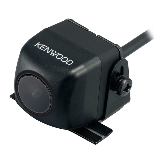
Take the time to read through this instruction manual.
Familiarity with installation and operation procedures will help you obtain the best performance
from your new Universal Camera.
For your records
Record the serial number, found on the back of the unit, in the spaces designated on the warranty card,
and in the space provided below. Refer to the model and serial numbers whenever you call upon your
Kenwood dealer for information or service on the product.
Model CMOS-230 Serial number
US Residence Only
Register your Kenwood product at www.Kenwoodusa.com
© 2014 JVC KENWOOD Corporation
CMOS-230
UNIVERSAL REAR VIEW CAMERA
INSTRUCTION MANUAL
CAMÉRA DE RECUL UNIVERSELLE
MODE D'EMPLOI
UNIVERSAL RÜCKFAHRKAMERA
BEDIENUNGSANLEITUNG
UNIVERSELE ACHTERUITRIJCAMERA
GEBRUIKSAANWIJZING
TELECAMERA PER RETROMARCIA UNIVERSALE
ISTRUZIONI PER L'USO
CÁMARA DE VISTA TRASERA UNIVERSAL
MANUAL DE INSTRUCCIONES
CÂMARA TRASEIRA UNIVERSAL
MANUAL DE INSTRUÇÕES
Register Online
B5A-0543-00 (W)
Table of Contents

Summary of Contents for Kenwood CMOS-230
- Page 1 Record the serial number, found on the back of the unit, in the spaces designated on the warranty card, and in the space provided below. Refer to the model and serial numbers whenever you call upon your Kenwood dealer for information or service on the product. Model CMOS-230 Serial number...
-
Page 2: Before Use/Installation
Before Use/ Installation Procedure • Before fi nally installing the unit, connect the wiring WARNING temporarily, making sure it is all connected up properly, and the unit and the system work. To prevent injury or fire, take the following • When mounting this unit, make sure none of the leads are precautions: trapped between this unit and the surrounding metalwork •... - Page 3 • Lay the cords by avoiding high-temperature areas. Use WARNING corrugated tubes for wiring inside the engine room. If a • If you connect the ignition wire (Red) to the car chassis cord contacts a high-temperature area of the vehicle, the (Ground), you may cause a short circuit, that in turn may coating may melt and cause short-circuiting, which may start a fi re.
-
Page 4: Recommended Installation Position
Installation Recommended Installation Position Mount the camera on the camera bracket. Mount so that the “KENWOOD” logo appears at the top. Examples of correct camera installation on the Fix the camera temporarily with tape, etc. rear of the vehicle Using a piece of tape, etc., fi x the camera temporarily. - Page 5 After adjusting the camera angle, tighten the retaining screws fi rmly. Inspect the retaining screws at times. If they are loose, tighten them fi rmly. Fix the camera fi rmly in position. Peel off the paper liner from the double-side adhesive tape on the camera bracket and attach it.
-
Page 6: Basic Connections
Connections Basic Connections Connect to the rearview camera video input or to the external video input of the video monitor. Video cord Navigation system/video monitor (commercially available) Camera Power cord Connect the camera to the camera connection cord. Camera’s cord length 1.5 m (4.92 feet), Power cord 7.5 m (24.6 feet) Fuse (2A) Fuse... -
Page 7: Specifications
Specifi cations Camera Unit Information on Disposal of Old Electrical and Electronic Equipment and Batteries (applicable Output video for countries that have adopted separate waste : Wide-angle mirror image (for rearview) collection systems) Sensor: 1/3.6-inch color CMOS sensor Products and batteries with the symbol (crossed- Number of pixels: Approx. -
Page 8: Fcc Caution
For U.S.A THIS DEVICE COMPLIES WITH PART 15 OF THE FCC RULES. OPERATION IS SUBJECT TO THE FOLLOWING TWO CONDITIONS: (1) THIS DEVICE MAY NOT CAUSE HARMFUL INTERFERENCE, AND (2) THIS DEVICE MUST ACCEPT ANY INTERFERENCE RECEIVED, INCLUDING INTERFERENCE THAT MAY CAUSE UNDESIRED OPERATION.


