
Related Manuals for Sony HDC3300R


Summary of Contents for Sony HDC3300R
- Page 1 HD COLOR CAMERA HDC3300R OPERATION MANUAL [English] 2nd Edition...
-
Page 2: Table Of Contents
Table of Contents Overview ................. 3 Features..................3 System Configuration Example........... 5 Precautions ................6 Phenomena Specific to CCD Image Sensors....... 6 Locations and Functions of Parts ........7 Accessory Attachments ...............7 Controls and Connectors ............. 8 Preparations ................. 15 Attaching a Lens................15 Adjusting the Flange Focal Length ........... -
Page 3: Overview
Adaptor to be shifted forward, giving it the same total longitudinal size as a standard studio-use camera, for The HDC3300R is the camera unit of a high-definition operability equivalent to that of a standard studio-use super-slow-motion video camera system with a 2/3-type camera. - Page 4 Various color-reproduction functions (in levels caused by the power-supply frequency for artificial lighting under which shooting is undertaken are not combination with HDCU3300R) averaged across the fields during supermotion shooting, with which exposure time is one-third that with normal Selection of multiple gamma tables speed shooting.
-
Page 5: System Configuration Example
Production of some of the peripherals and related devices shown in the figures has been discontinued. For advice for choosing devices, please contact your Sony dealer or a Sony sales representative. HDVF-550/C730W/C550W/ a) SD component outputs of the EL75 Viewfinder HKCU1003 are not supported. -
Page 6: Precautions
• when operating at a high environmental temperature Precautions • when you have raised the master gain (sensitivity) This product has a compensation function and the problem may be alleviated by automatic black balance adjustment (see page 20). Note on laser beams Laser beams may damage the CCDs. -
Page 7: Locations And Functions Of Parts
Locations and Functions of Parts Accessory Attachments a VF connector b Shoulder strap fitting post c Accessory shoe d Viewfinder left-right positioning ring e Viewfinder front-rear positioning lever and lock knob f Lens cable clamp g Lens fixing lever S E R IE S h Lens mount cap i Lens mount... -
Page 8: Controls And Connectors
j LENS connector (12-pin) l Shoulder pad Connect the lens cable. The camera can control the lens You can adjust the position so that you can get the best functions through this cable. balance for shooting with the camera on your shoulder. For details, see “Adjusting the Shoulder Pad Position”... - Page 9 e FILTER LOCAL button The access lamp lights in red while writing or reading data While holding this button depressed, press either of the to/from a “Memory Stick.” filter select buttons to select the ND or CC filters. Note When the access lamp is lit, do not insert/remove the f AUTO W/B BAL (white and black balance “Memory Stick”...
- Page 10 Front left S E R IE S d SHUTTER switch a RET 1 button e INTERCOM LEVEL control b MIC 1 IN connector c MIC power switch f RET 2 button a RET 1 (return video 1) button The intercom level adjustment is enabled when the The return video 1 signal from the camera control unit is INTERCOM 1 and 2 LEVEL/MIC switches (on the SY- monitored on the viewfinder screen while this button is...
- Page 11 Rear b Tally lamp and switch Shoulder strap fitting post (page 7) Operation panel (page 12 or 13) c CCU connector Not used d PROMPTER 2 connector Connector panel (page 14) a CAMERA POWER switch e CALL button a CAMERA POWER switch series Master Setup Unit, will light.
- Page 12 Operation panel SY type: For JN4 (East Asia) and SYL (USA, Canada, and other countries) models (for NTSC areas) b RET1 button and select switch a INTERCOM1 and INTERCOM2 controls and switches c RET2 button and select switch d LIGHT switch PGM1 control PGM2 control PGM1...
- Page 13 European type: For CED (Europe) and E33 (China and South Asia) models (for PAL areas) b RET1 button and select switch a INTERCOM1 and INTERCOM2 controls and switches c RET2 button and select switch ENG control d LIGHT switch PROD control PGM1 control PGM2 control RET1...
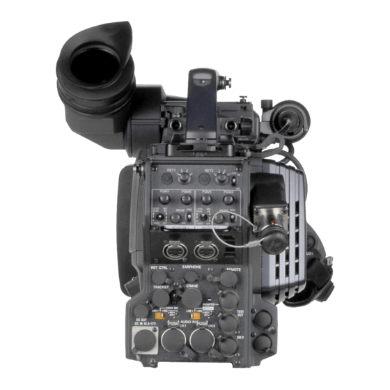
- Page 14 Connector panel INTERCOM 1 INTERCOM 2 g INTERCOM 1 and 2 connectors a EARPHONE jack RET CTRL REMOTE b RET CTRL connector EARPHONE h REMOTE connector c CRANE connector RET IN CRANE GENLOCK IN TRACKER d TRACKER connector i PROMPTER connector PROMPTER FRONT MIC AES/EBU...
-
Page 15: Preparations
Adjustment of the flange focal length (the distance Note between the lens mount attachment plane and the imaging In the case of supplying +12 V, contact a Sony service or plane) is necessary in the following situations: sales representative. • The first time a lens is attached •... -
Page 16: Attaching A Viewfinder
Attaching procedure Note The various parts of the lens used in adjusting the flange VF connector focal length are in different positions on different lenses. Viewfinder stopper Refer to the lens’ operation manual. Attaching procedure Set the iris control to manual, and open the iris fully. Place a flange focal length adjustment chart approximately 3 meters from the camera and adjust the lighting to get an appropriate video output level. - Page 17 Loosen the viewfinder left-right positioning ring. Note Lock the viewfinder in a slightly forward position before Slide the viewfinder left or right to move it into a good rotating it upwards. If the viewfinder is in its rearmost viewing position. position, the arm of the viewfinder rotation bracket will strike the grip.
-
Page 18: Attaching The Cable Clamp Belt (Supplied)
Adjust the front-rear position so that the camera Secure the cable clamp belt to the camera, using the handle does not interfere when you rotate the BKW- two supplied +B3× 8 screws. 401 arm upwards. Not to interfere × 8 screws 1 Release the buckle, 2 bundle the cable with the Attaching the Cable Clamp Belt belt, 3 then lock the buckle again. -
Page 19: Adjusting The Shoulder Pad Position
Mounting procedure Adjusting the Shoulder Pad Position Attach the tripod adaptor to the tripod and secure it You can shift the shoulder pad from its center position with the screw. (factory setting) backward by up to 10 mm (3/8 inch) or forward by up to 25 mm (1 inch). -
Page 20: Adjustments And Settings For Shooting
To remove the camera from the tripod adaptor Adjustments and Hold down the red button and pull the lever in the direction of the arrow. Settings for Shooting Adjusting the Black Balance and White Balance In order to maintain high picture quality when using the camera, it is necessary to set the black balance and white balance appropriately for the conditions. - Page 21 ABB:EXECUTING After a few seconds the adjustment process will be complete, and the message “ABB: OK” will be displayed. The adjusted value is automatically stored in memory. Notes CC filter select button • During black balance adjustment, the iris will be automatically closed.
-
Page 22: Setting The Electronic Shutter
Push the AWB (auto white balance) button of the RCP Shutter modes and speeds or MSU. Shutter Usage Shutter speeds mode When the DISPLAY switch is set to the DISPLAY position, a message like the one in the figure below Standard 1/100, 1/125, 1/250, Use to obtain clear... -
Page 23
The CONTENTS page of the OPERATION menu is PEAK COLOR: Turn ON/OFF the function to displayed. change the color where the detail signal is strongest. CONTENTS CHROMA LEVEL: To reduce the chroma 01.
components of the video signal (only for video 02.<'!'IND>... -
Page 24: Setting The Flicker-Reduction Function
To use the level indicator Setting the Flicker-Reduction Setting INDICATOR to ON displays the level Function indicator on the viewfinder. You can set the display format with the menu items With artificial lighting, particularly fluorescent lights and below. MODE: Set the type and position of the indicator. mercury-vapor lamps, the brightness appears to be LEVEL: Set the density and the response speed of the constant, but in fact the strength of the red, green, and blue... -
Page 25
Note
S09 TOP With the rapid response time, correction can respond REDUCER : OFF FREQUENCY : 60Hz to a rapid change in fluctuations. However, excess GAIN OFFSET correction amount may result when there is instant ADV MODE : ENABLE AREA SELECT : H&V change (e.g.: another subject is cutting across the scene). -
Page 26: Viewfinder Screen Status Display
Viewfinder Screen Status Display Besides the video image, the viewfinder can display text status, as well as items such as a center marker or safety and messages showing the camera settings and operation zone marker. When the DISPLAY switch is set to ON Items set to ON using the menu or related switches will be displayed on the upper and lower edges of the screen. -
Page 27: Menu Operations
When you press the CANCEL/STATUS Menu Operations switch toward STATUS The status display is changed to show the following items: The menus displayed on the viewfinder screen enable a Assignable switch indication various settings of the camera. b Format indication The following controls are used to operate the menus. -
Page 28: Selecting Pages
Available menus The CONTENTS page or the last operated page of the selected menu is displayed. USER menu This menu can include menu pages selected from among Selecting Pages the OPERATION, PAINT, MAINTENANCE, FILE, and DIAGNOSIS menus, for convenience. Changing, adding, and deleting pages can be performed with the USER When selecting a page from a CONTENTS MENU CUSTOMIZE menu. -
Page 29: Setting The Menu Items
Rotate the MENU SEL knob/ENTER button to flip Push on the MENU SEL knob/ENTER button. through the pages. The “?” mark will change back to the arrow marker ), and the new setting will be registered. When the desired page is displayed, push on the MENU SEL knob/ENTER button. -
Page 30: Editing The User Menu
To end menu operations their initial state. You can register up to 10 items, including blank lines, on each of these pages. Set the DISPLAY switch to OFF. To add items to a page Proceed as follows. Editing the USER Menu While holding the CANCEL/STATUS switch pressed You can select desired pages and items from the toward STATUS, move the DISPLAY switch from the... - Page 31 Turn the MENU SEL knob/ENTER button to move the EDIT FUNCTION arrow marker ( ) to the item to be moved then push INSERT MOVE on the MENU SEL knob/ENTER button. DELETE BLANK The EDIT FUNCTION screen appears. Select “MOVE” then push on the MENU SEL knob/ ENTER button.
- Page 32 If this is the first time the USER MENU CUSTOMIZE the arrow marker ( ) to “ESC” at the top right of the menu has been displayed, the CONTENTS page of the screen, then push on the MENU SEL knob/ENTER button. menu appears.
-
Page 33
Push on the MENU SEL knob/ENTER button. The page selected in step 1 is moved to the position selected in step 3. In the above example,
moves to the “04” position, and the and following pages move down one line. Menu Operations... -
Page 34: Menu List
Menu List This section shows the menus to be displayed on the Notes viewfinder screen in tables. HDLA: HDLA1500-series Large Lens Adaptor • For the pages that have been registered in the USER CCU: HDCU3300R Camera Control Unit menu at the factory, the USER menu page numbers are Execute by ENTER: Execute by pushing on the MENU indicated in parenthesis in the No. - Page 35 Page title Item Default Settings Remarks <'!' IND> [IND] ON ON, OFF [IND]: Set whether to be (U05) included in the status [NORMAL] 1 – – – – 1, 2, 3, 4, 5 (combination indications on the allowed) viewfinder screen (see [IND] ON ON, OFF page 27).
-
Page 36
Page title Item Default Settings Remarks
VF DETAIL ON, OFF, (ON), (OFF) Settings in ( ): When HDLA (U02) attached (cannot be 0 to 100%, (0 to 100%) changed) CRISP –99 to 99 FREQUENCY 9M, 14M, 18M FAT MODE ON, OFF FLICKER ON, OFF... -
Page 37
Page title Item Default Settings Remarks
GAIN [L] 0 dB –3, 0, 3, 6, 9, 12 dB (U09) [M] 6 dB –3, 0, 3, 6, 9, 12 dB [H] 12 dB –3, 0, 3, 6, 9, 12 dB ASSIGNABLE OFF, RETURN1 SW, JN4/SYL models only. - Page 38 Page title Item Default Settings Remarks INTERCOM1 MIC CARBON DYNAMIC, CARBON, (U13) MANUAL LEVEL (–20 dB) –60 dB, –50 dB, –40 dB, Settings in ( ): With DYNAMIC –30 dB, –20 dB, (–60 dB), or CARBON (cannot be (–50 dB), (–40 dB), (–30 dB), changed) (–20 dB)
-
Page 39
Page title Item Default Settings Remarks
EARPHONE SEPARATE SEPARATE, MIX RECEIVE SELECT INTERCOM LEFT - - - , LEFT, RIGHT, BOTH JN4/SYL models only LEFT - - - , LEFT, RIGHT, BOTH CED/E33 models only PROD LEFT - - - , LEFT, RIGHT, BOTH CED/E33 models only PGM1 RIGHT... -
Page 40: Paint Menu
PAINT Menu Menu page Item⁄ Default Settings RemarksFLARE ON, OFF GAMMA ON, OFF BLK GAM ON, OFF KNEE ON, OFF WHT CLIP ON, OFF DETAIL ON, OFF LVL DEP ON, OFF SKIN DTL ON, OFF MATRIX ON, OFF -
Page 41
Menu page Item⁄ Default Settings Remarks
[R] [G] [B] [M] R, G, B, and M (master) values LEVEL –99 to 99 can be independently set. RANGE HIGH LOW, L.MID, H.MID, HIGH ON, OFF TEST OFF, SAW, 3STEP, 10STEP ... -
Page 42
Menu page Item⁄ Default Settings Remarks
H/V RATIO –99 to 99 Absolute value is displayed in ABS mode. FREQ –99 to 99 Absolute value is displayed in ABS mode. MIX RATIO –99 to 99 Absolute value is displayed in ABS mode. -
Page 43
Menu page Item⁄ Default Settings Remarks
SHUTTER ON, OFF, (ON), (OFF) Settings in ( ): When a remote control unit/panel or a CCU is not connected (cannot be changed) JN4/SYL models: 59.94i: 1/100, 1/125, 1/250, Step shutter setting 1/100 (sec) 1/500, 1/1000, 1/2000 CED/E33 models: 50i: 1/60, 1/125, 1/250,... -
Page 44: Maintenance Menu
MAINTENANCE Menu Menu page Item⁄ Default Settings RemarksAUTO BLACK Execute by ENTER. AUTO WHITE Execute by ENTER. AUTO LEVEL Execute by ENTER. AUTO WHITE SHADING Execute by ENTER. AUTO BLACK SHADING Execute by ENTER. TEST OFF, SAW, 3STEP, 10STEP ... -
Page 45
Menu page Item⁄ Default Settings Remarks
AUTO IRIS ON, OFF, (ON), (OFF) Settings in ( ): When a remote control unit/panel or a CCU is not connected (cannot be changed) WINDOW 1, 2, 3, 4, 5, 6 Select the auto iris windows: The shaded parts indicate the area where light detection occurs. -
Page 46
Menu page Item⁄ Default Settings Remarks
OUTPUT SD-SYNC, HD-SYNC, VF, (U17) (PWR SAVE) Displayed in POWER SAVE mode only VBS-OUT CHARACTER ON, OFF GAIN –127 to 127 CHROMA –127 to 127 SETUP ON, OFF JN4/SYL models only (displayed when the format is NTSC) HD-SYNC-OUT V-PHASE... -
Page 47: File Menu
FILE Menu Five types of files can be used for easy adjustments of the For the specific items included in these files, refer to the camera; Operator, Reference, Scene, OHB, and Lens. Maintenance Manual. You can store the items set with the OPERATION menu and customized USER menu in the Operator file. -
Page 48
Menu page Item⁄ Default Settings Remarks
STORE FILE Execute by ENTER. To store the current settings of the reference file items in the reference file in internal memory STANDARD Execute by ENTER. To read the standard values in the reference file in internal memory ALL PRESET Execute by ENTER. -
Page 49: Diagnosis Menu
Vx.xx SSM Vx.xx SSM HKCT Vx.xx With HKC-T3300 installed onlyVx.xx (U22) PANEL Vx.xx With HDLA attached only HKCT Vx.xx With HKC-T3300 installed only MODEL HDC3300R xxxxxxx OPTION Displayed if any option is installed. Menu List... -
Page 50: Using A "Memory Stick
“Memory Stick” • To prevent data loss, make backups of data frequently. In no event will Sony be liable for any loss of data. • Unauthorized recording may be contrary to the provisions of copyright law. When you use a “Memory Access lamp Stick”... -
Page 51: Specifications
Sony Corporation. Power requirements 240 V AC, 1.4 A (max.) • “Memory Stick PRO Duo and 12 V DC, 8.6 A (max.) are trademarks of Sony Corporation. Operating temperature • “MagicGate” and are trademarks − 20°C to +45°C (− 4°F to +113°F) of Sony Corporation. -
Page 52: Optional Accessories
Switch label 1, 2 (1 each) HKC-T3300 CCD Block Adaptor When used with this camera, the HKC-T3300 must be updated to the latest version. For details, consult Sony service personnel. Design and specifications are subject to change without notice. Dimensions... - Page 53 Note Always verify that the unit is operating properly before use. SONY WILL NOT BE LIABLE FOR DAMAGES OF ANY KIND INCLUDING, BUT NOT LIMITED TO, COMPENSATION OR REIMBURSEMENT ON ACCOUNT OF THE LOSS OF PRESENT OR PROSPECTIVE PROFITS DUE TO FAILURE OF...
- Page 54 The material contained in this manual consists of information that is the property of Sony Corporation and is intended solely for use by the purchasers of the equipment described in this manual. Sony Corporation expressly prohibits the duplication of any...
- Page 55 Sony Corporation HDC3300R (UC/CE/SY/JN/E) 4-479-637-11(1) © 2013...