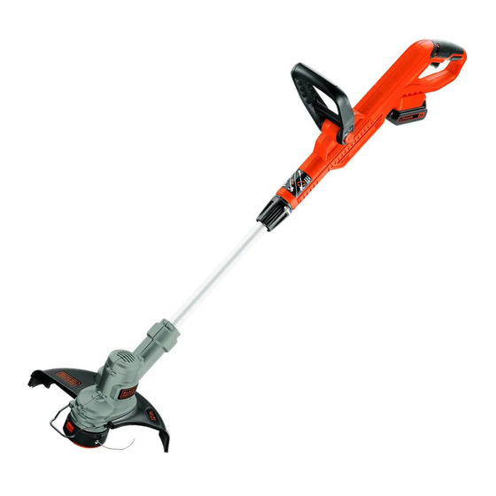
Black & Decker LST300 Instruction Manual
Black & decker lst300 20v max trimmer/edger
Hide thumbs
Also See for LST300:
- Instruction manual (68 pages) ,
- Instruction manual (41 pages) ,
- Instruction manual (37 pages)
Table of Contents
20V max* Trimmer/edger
INSTRUCTION MANUAL
CATALOg NUMBER
LST300
KEY INFORMATION YOU SHOULD KNOW:
• The guard must be installed before trimming or edging - if not, the motor will overheat.
• When replacing the line, use only .065 inch diameter ROUND line (B&D Model #AF-100 is
recommended) - otherwise the trimmer will not function properly.
• Do not bump the feed head against the ground - it will disrupt the automatic feed mechanism.
Thank you for choosing Black & Decker! To register your new product go to
www.BlackandDecker.com/NewOwner
PLEASE READ BEFORE RETURNINg THIS PRODUCT FOR ANY REASON.
If you have a question or experience a problem with your Black & Decker purchase, go to
http://www.blackanddecker.com/instantanswers
If you can't find the answer or do not have access to the Internet,
call 1-800-544-6986 from 8 a.m. to 5 p.m. EST Mon. - Fri. to speak with an agent.
Please have the catalog number available when you call.
SAvE THIS MANUAL FOR FUTURE REFERENCE.
vEA EL ESPANOL EN LA CONTRAPORTADA.
INSTRUCTIVO DE OPERACIÓN, CENTROS DE SERVICIO Y PÓLIZA DE GARANTÍA.
ADvERTENCIA: LÉASE ESTE INSTRUCTIVO ANTES DE USAR EL PRODUCTO.
*Maximum initial battery pack voltage (measured without a workload) is 20 volts. Measured under a workload, nominal voltage is 18.
1
Table of Contents

Summary of Contents for Black & Decker LST300
- Page 1 20V max* Trimmer/edger INSTRUCTION MANUAL CATALOg NUMBER LST300 KEY INFORMATION YOU SHOULD KNOW: • The guard must be installed before trimming or edging - if not, the motor will overheat. • When replacing the line, use only .065 inch diameter ROUND line (B&D Model #AF-100 is recommended) - otherwise the trimmer will not function properly.
- Page 3 Replacement: Spool (AF-100) Cap (RC-100) Remplacement : Bobine (AF-100) Capuchon (RC-100) Repuestos: Carrete (AF-100) Tapa (RC-100) SAFETY gUIDELINES - DEFINITIONS It is important for you to read and understand this manual. The information it contains relates to protecting YOUR SAFETY and PREvENTINg PROBLEMS. The symbols below are used to help you recognize this information.
- Page 4 CAUTION: Failure to comply with the recommendations outlined in the key information section will void warranty. WARNINg: Some dust created by this product contains chemicals known to the State of California to cause cancer, birth defects or other reproductive harm. Some examples of these chemicals are: • compounds in fertilizers • compounds in insecticides, herbicides and pesticides...
- Page 5 breakage of parts, mounting, and any other condition that may affect its operation. A guard or other part that is damaged should be properly repaired or replaced by an authorized service center unless otherwise indicated elsewhere in this manual. • DO NOT immerse trimmer in water or squirt it with a hose.
- Page 6 • An extension cord must have adequate Minimum gauge for Cord Sets wire size (AWg or American Wire gauge) volts Total Length of Cord in Feet for safety. The smaller the gauge number 120V 0-25 26-50 51-100 101-150 of the wire, the greater the capacity of the 240V 0-50 51-100 101-200 201-300...
- Page 7 WARNINg: Fire hazard. Do not store or carry battery so that metal objects can contact exposed battery terminals. For example, do not place battery in aprons, pockets, tool boxes, product kit boxes, drawers, etc., with loose nails, screws, keys, etc. Transporting batteries can possibly cause fires if the battery terminals inadvertently come in contact with conductive materials such as keys, coins, hand tools and the like.
- Page 8 INSTALLINg AND REMOvINg THE BATTERY PACK WARNINg: Make certain the lock-off button is engaged to prevent switch actuation before removing or installing battery. TO INSTALL BATTERY PACK: trimmer Insert battery pack (2) firmly into until an audible click is heard as shown in figure C. Ensure battery pack is fully seated and fully latched into position.
- Page 9 OPERATINg INSTRUCTIONS WARNINg: Always use proper eye protection that conforms to ANSI Z87.1 (CAN/CSA Z94.3) while operating this power trimmer. WARNINg: Remove the battery before making any assembly, adjustments, or changing accessories. Such preventive safety measures reduce the risk of starting the trimmer accidentally. CAUTION: Before you begin trimming, only use the appropriate type of cutting line.
- Page 10 REPLACINg THE SPOOL • Remove battery from trimmer. • Depress the tabs (14) and remove the spool cap (8) from the spool housing (15) in the trimmer head (figure M). • For best results, replace spool with Black & Decker model # AF-100. • Grasp empty spool with one hand and spool housing with other hand and pull spool out. • If lever (16) in base of housing becomes dislodged, replace in the position as shown in figure N before inserting new spool into housing. • Remove any dirt and grass from the spool and housing. • Unfasten the end of the cutting line and guide the line into the eyelet (18) figure O. • Take the new spool and push it onto the boss (17) (figure N) in the housing.
- Page 11 TROUBLESHOOTINg TRIMMER RUNS SLOWLY • Remove Battery from tool. • Check that the spool housing can rotate freely. Carefully clean it if necessary. • Check that the cutting line does not protrude more than approximately 5-3/8 inches (136mm) from the spool. If it does, cut it off so that it just reaches the line trimming blade. AUTOMATIC LINE FEED DOES NOT WORK • Remove Battery from tool.


