Table of Contents
SERVICE MANUAL
1) Specifications ...............................................................................1
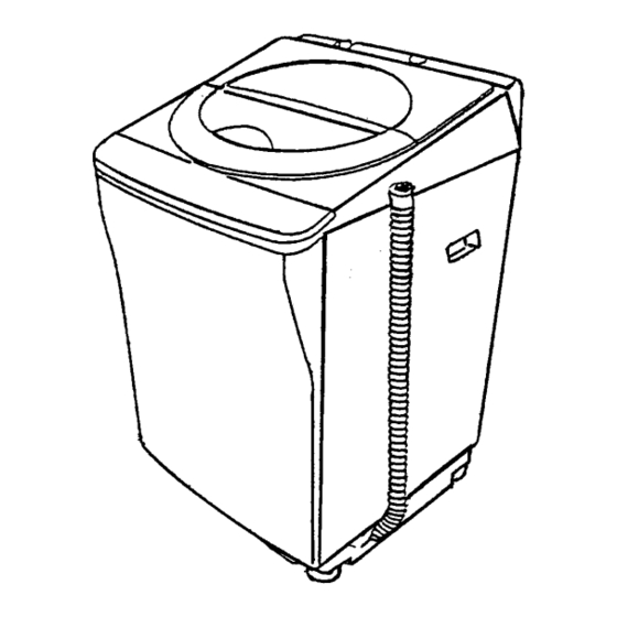
2) Outer dimensions .........................................................................1
3) Water course diagram ...................................................................2
4) Electric circuit diagram ................................................................3
5) Method of operation ....................................................................4
6) Content of fully Automatic Washing program ..............................5
7) Operation of fully Automatic Washing...........................................6
8) Procedure of time presetting program ..........................................9
9) Indication and judgment of trouble................................................10
10) Inspection mode of service man .................................................11
11) Care of service..............................................................................12
12) Flow chart of trouble shooting .....................................................15
13) Trouble shooting of Bearing Ass y ..............................................19
14) Exploded view...............................................................................21
15) Part list ........................................................................................24
Automatic Washer
Product Code No .
300-849-85
TABLE OF CONTENTS
FILE NO.
ASW U1100T
(MALAYSIA)
240V
50 Hz
M3
PAGES
REFERENCE.No.SM930202
H
Table of Contents
Troubleshooting

Related Manuals for Sanyo ASW U1100T


Summary of Contents for Sanyo ASW U1100T
-
Page 1: Table Of Contents
FILE NO. SERVICE MANUAL Automatic Washer ASW U1100T (MALAYSIA) Product Code No . 300-849-85 240V 50 Hz TABLE OF CONTENTS ITEM PAGES 1) Specifications ................1 2) Outer dimensions .................1 3) Water course diagram ..............2 4) Electric circuit diagram ..............3 5) Method of operation ..............4 6) Content of fully Automatic Washing program ......5... -
Page 2: Item
1. Specifications ITEM SPECIFICATION ITEM SPECIFICATION Overall dimensions 589(W) x 620(D) x 988(H) Motor 4 Poles- class E AM V14JM Net weight 43 kg Capacitor Ass y 8.0 F 444 V.AC Washing method Whirlpool Pulsator Pulley Outer diameter: 110 mm Driving system V-Belt + gear driving Motor Pulley... -
Page 3: Water Course Diagram
3. Water course diagram Feed Hose Ass y Magnetic Valve Pour Inlet Outer Tub Drum Spin Tub Drum Spin Tub Boss Circulate Hose Air Trap Hose Drain Valve Drain Hose Overflow Hose Lint Filter Ass y Magnetic Valve Pour Inlet Spin Tub Drum / Outer Tub Drum Water supply : Spin Tub Drum / Outer Tub Drum... -
Page 4: Electric Circuit Diagram
4. Electric circuit diagram For the purpose of safety, please use only designated parts. - 3 -... -
Page 5: Method Of Operation
5. Method of operation Name and function of buttons on control panel: When you press those buttons, the setting program and indicators (LED) will change alternately. BUTTON SETTING PROGRAM INDICATION OF LED To turn the power ON and When you press the power switch to turn power ON, NORMAL POWER OFF alternately. -
Page 6: Content Of Fully Automatic Washing Program
6. Contents of fully Automatic Washing program PROGRAM WASH RINSE SPIN TOTAL *8 -10 Once shower. *5 -6 Depending on the Wash load NORMAL and the kind of laundry. Water saver. *11 -13 *6 -7 Depending on the Wash load Twice Overflow HEAVY DUTY and the kind of laundry. -
Page 7: Operation Of Fully Automatic Washing
7. Operation of fully Automatic Washing program NORMAL, HEAVY DUTY, CUSTOM, SOAK Course: Turn on the power switch (ON/ OFF) Load the laundry into the washer Press the ONE TOUCH SELECT to select the washing course Press the START/ PAUSE button The washer begins rotating the Pulsator right then left two times PULSATOR ROTATES to check the volume of the laundry and select the most suitable... - Page 8 After water level reaches reset point, draining course continues for 1 40 . DRAIN Before completion of spinning, electrical continuity of motor breaks off and motor rotates continuously by inertia. The Brake Ass y activates while Spin Tub revolution speed is slowing down. During Spinning: If the clothes clump on one side and/ or the SPIN Wash/ Spin Tub becomes unbalanced, the microchip will detect...
- Page 9 DRY CARE Course: Turn on the power switch (ON/ OFF). Load the laundry into the washer. Press ONE TOUCH SELECT to select the Dry Care course. Press the START/ PAUSE button. Water is supplied to MED level. WATER IS SUPPLIED Depending on the volume of laundry, for best results, use LOW2, HIGH water level.
-
Page 10: Procedure Of Time Presetting Program
8. Preset time program Turn on the power switch (ON/OFF). HOW TO USE THE PRESET BUTTON The PRESET time can be changed by pressing the SET button. 6 hours Load the laundry into the washer. 12 hours Turn the faucet on. No setting 1 hours 5 hours... -
Page 11: Indication And Judgment Of Trouble
9. Indication and judgment of troubles Trouble judgment : During operating, when trouble occurs, microchip will judge the cause and stop the present operation. Water level indicator blinks on and off and buzzer sounds. Troubles Judgment Check The Safety Switch works 3 times Spin Tub is in unbalance, the laundry leant to Abnormal condition of spinning... -
Page 12: Inspection Mode Of Service Man
10. Inspection mode for service man Method to enter service inspection mode: (1) While holding the PROGRAM button down at pressed state, press the POWER SWITCH button. (2) Hold the program button down at pressed state, press the START/ PAUSE button three times. The operation of inspection mode: (1) Press PROGRAM button to set the inspection mode. -
Page 13: Care Of Service
11. Care of service : Disconnect the power cord during servicing for your safety. Removing Front Panel (1) Take two fixing screws out. (2) Pull Front Panel down and lift it up for taking out. (3) Reverse the order of the steps above to put the unit back. Replacing Control Plate and Printed Circuit Board (1) Follow the steps (1) to (2) of the Replacing Front Panel . - Page 14 Replacement of Top Plate (1) Follow the steps (1) to (2) of Replacing Font Panel . (2) Follow the steps (2) to (4) of Replacing Control Plate . (3) Follow the steps (1) to (3) of Removing Back Plate . (4) Take out 4 screws that are holding Top Plate and Frame.
- Page 15 Replacement of Suspension Rod Ass y: Remove the screws which are seemed on Top plate, follow the steps of Replacing top plate . Lay the washer down left or right suitably on the floor (It is necessary to have a soft cloth or blanket to protect the washer).
-
Page 16: Flow Chart Of Trouble Shooting
12. Flow chart of trouble shooting TROUBLE INSPECTION CAUSES REMEDY a. Power Source Any indicators and Is fuse blown ? Deterioration of fuse Replace beep do not work Motor is defective Replace when the power Capacitor is defective Replace switch is on and the start button is Poor connection of the 14 pressed... - Page 17 TROUBLE INSPECTION CAUSES REMEDY c. Wash/ Rinse Washing cycle Does the Spin Tub Bearing Ass y is Replace does not start rotate normally when defective. even if water the SELECT button is keeps the selected set to SPIN ? Poor connection of the 14 Replace water level.
- Page 18 TROUBLE INSPECTION CAUSES REMEDY d. Drain Foreign matter in Valve Clean valve inside Water does not Is the Magnetic coil Valve Spring is deformed Replace Valve Spring drain out working normally ? Replace Valve Bellow Valve Bellows is or replace Valve deformed Spring Magnetic Coil lead wire...
- Page 19 TROUBLE INSPECTION CAUSES REMEDY f. Buzzing and rattling Buzzing/ rattling Is water pressure high Screw of Magnetic Valve Tighten screws. during water (more than 10kg.f/ cm is loose. supply. Something in Magnetic Replace. Valve. High Faucet open too widely. Adjust faucet turning. Buzzing/ rattling Does some noise sound Adjust.
-
Page 20: Trouble Shooting Of Bearing Ass Y
13. Troube shooting of Bearing Assembly (Bearing Case Complete) For Fully Automatic Washing Machines. Abnormal (Squeaky) sound is heard during washing: Symptom: The squeaky sound occurs when the brake system operates. During washing, the Pulsator turns CW (clockwise) and CCW (counterclockwise), producing water flow in the CW and CCW direction. - Page 21 Spin tub does not rotate (Spin Tub is locked): Symptom: Spin Tub does not rotate despite water extraction starting stage. Cause: When it is caused by electric signals, water level sensor, Magnetic Coil, motor receptacle Housing Assembly, PCB Complete, Safety Switch, etc are likely to response. However, the troubles are mainly caused by related mechanical parts in this case.
-
Page 22: Exploded View
14. Exploded View - 21 -... - Page 23 - 22 -...
- Page 24 - 23 -...
- Page 25 - 24 -...
-
Page 26: Part List
15. Part List Part Name Service Code Q'Ty Specification PCB Complete 617-260-0239 SCR TPG TRS 4x16 411-007-5606 Control Plate 617-263-5347 202N Stopping Pin 617-226-9603 RED COLOUR Membrane Plate 617-259-8970 Washer Lid Ass'y 617-259-8161 6.1.1 Washer Lid A SER-SPC-0010 634N SILVER 6.1.2 Washer Lid B SER-SPC-0012... - Page 27 Part Name Service Code Q'Ty Specification Top Plate 617-259-9700 202N SCR TPG TRS 4x12 411-074-5806 SCR TPG TRS 4x20 411-007-1004 FIX TOP PLATE SCR TPG TRS 4x10 411-074-5004 FIX FRAME ATTACH Tab Housing Ass y 617-245-6614 220-240V Tab Housing Ass y 617-250-2557 220-240V, M3 IEC 35.1...
- Page 28 Part Name Service Code Q'Ty Specification Special Screw 617-029-0050 4x10 Lead Wire Ass y 617-192-7962 Pulsator Screw 617-026-9575 SUS-304 Pulsator Screw Washer 617-026-9636 Pulsator 617-259-7669 P.P AR564 Pulsator Washer 617-183-6431 SUS-430 T1.5 Outer Tub Cover 617-259-7645 SCR TPG TRS 4x16 411-007-5606 Suspension Rod Ass'y 617-259-7102...
- Page 29 106.4.3 Balance Weight Ass y 617-259-7423 106.4.4 Spin Tub Boss SER-SPC-0016 Lint Filter Ass y 617-234-9282 NW-32 Packing 617-223-7039 EPDM SCR TPG TRS 4x12 411-074-5806 Notice Label 617-180-8599 Special Screw 617-029-0227 Rubber Damper 617-138-2235 SANYO Electric Co., Ltd. Osaka, Japan - 28 -...