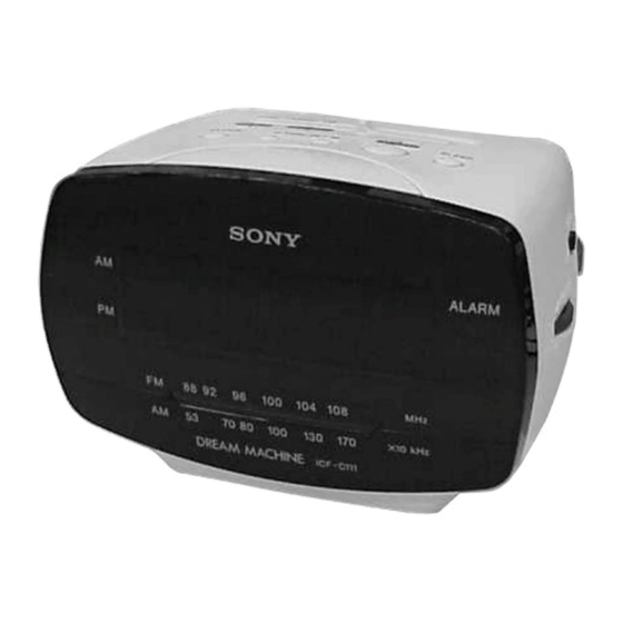
Sony ICF-C111 Service Manual
Fm/am clock radio
Hide thumbs
Also See for ICF-C111:
- Specifications (2 pages) ,
- Operating instructions (2 pages) ,
- Limited warranty (1 page)
Table of Contents
SERVICE MANUAL
Ver 1.1 2001. 05
Sony Corporation
9-873-094-12
2001E0400-1
Personal Audio Company
© 2001.5
Shinagawa Tec Service Manual Production Group
SPECIFICATIONS
Time display
12-hour system (AR, E13, SP)
24-hour system (E92, MX)
Frequency range
FM: 87.5 - 108 MHz
AM: 530 - 1710 kHz
Speaker
Approx. 6.6 cm (2
inches) dia., 8 ohm
5/8
Power output
100 mW (at 10% harmonic distortion)
Power requirements
120 V AC, 60 Hz (E92, MX)
220 - 230 V AC, 50 Hz (AR, SP)
220 - 230 V AC, 60 Hz (E13)
For the power back-up function: 9 V DC, one 6F22 battery
Battery life
Approx. 60 hours, using Sony S-006P (6F22) battery
Dimensions
Approx. 146.5 × 100.5 × 123 mm (w/h/d)
× 4 × 4
(5
inches) incl. projecting parts and controls
7/8
7/8
Mass
Approx. 580 g (1 lb 4.4 oz) not incl. battery
Design and specifications are subject to change without notice.
• Abbreviation
AR : Argentina model
E13 : AC 220 – 230 V area in E model
E92 : AC 120 V area in E model
MX : Mexican model
SP
: Singapore model
ICF-C111
FM/AM CLOCK RADIO
E Model
1
Table of Contents

Related Manuals for Sony ICF-C111


Summary of Contents for Sony ICF-C111
- Page 1 220 - 230 V AC, 60 Hz (E13) For the power back-up function: 9 V DC, one 6F22 battery Battery life Approx. 60 hours, using Sony S-006P (6F22) battery Dimensions Approx. 146.5 × 100.5 × 123 mm (w/h/d) × 4 × 4 inches) incl.
-
Page 2: Table Of Contents
COMPONENTS IDENTIFIED BY MARK 0 OR DOTTED LINE WITH MARK 0 ON THE SCHEMATIC DIAGRAMS AND IN THE PARTS LIST ARE CRITICAL TO SAFE OPERATION. REPLACE THESE COMPONENTS WITH SONY PARTS WHOSE PART NUMBERS APPEAR AS SHOWN IN THIS MANUAL OR IN SUPPLEMENTS PUBLISHED BY SONY. -
Page 3: Servicing Notes
ICF-C111 SECTION 1 SERVICING NOTES 1-1. CORD DRESSING (POWER CORD) 1) Connect the power cord as shown in the figure. 2) Mount the chassis with screws (P 3 × 10). Note: Tighten completely the screws (P 3 × 10). cabinet (lower) -
Page 4: General
ICF-C111 SECTION 2 GENERAL This section is extracted from instruction manual. -
Page 5: Disassembly
ICF-C111 SECTION 3 DISASSEMBLY • The equipment can be removed using the following procedure. Panel (Front) Cabinet (Upper) Assy Chassis Section Main Board Note : Follow the disassembly procedure in the numerical order given. 3-1. PANEL (FRONT) claws claw 2 panel (front) -
Page 6: Cabinet (Upper) Assy
ICF-C111 3-2. CABINET (UPPER) ASSY 3 cabinet (upper) assy 1 screws (P 3x30) 2 screws (P 3x30) 3-3. CHASSIS SECTION from speaker 2 screw (P 3x10) from MAIN board 3 chassis section 1 CN701... -
Page 7: Main Board
ICF-C111 3-4. MAIN BOARD 1 screw (P 3x10) 2 MAIN board claw claw... -
Page 8: Electrical Adjustments
ICF-C111 SECTION 4 ELECTRICAL ADJUSTMENTS FM SECTION 0 dB = 1 µV FM FREQUENCY COVERAGE ADJUSTMENT Setting: Adjust for a maximum reading on level meter. BAND switch: FM VOLUME switch: MIN 86.5 MHz 109.5 MHz FM RF signal FM lead wire... - Page 9 ICF-C111 Adjustment Location: CT3, L3 TRACKING LEAD WIRE CT1, L1 ADJUSTMENT ANTENNA TRACKING ADJUSTMENT – MAIN board (component side) – TUNING BAND ADJUSTMENT CN701 CT4, L4 CT2, L2 (SPEAKER) FREQUENCY FREQUENCY COVERAGE COVERAGE ADJUSTMENT ADJUSTMENT...
-
Page 10: Diagrams
ICF-C111 SECTION 5 DIAGRAMS THIS NOTE IS COMMON FOR PRINTED WIRING BOARDS AND SCHEMATIC DIAGRAMS. Common Note on Schematic Diagram: • All capacitors are in µF unless otherwise noted. pF: µµF 50 WV or less are not indicated except for electrolytics and tantalums. -
Page 11: Block Diagram
ICF-C111 5-1. BLOCK DIAGRAM MAIN BOARD VREG w VOLUME BAND 10.7MHz LEAD WIRE ANTENNA DISCRI BAND SW DISCRIMINATOR FM ANT CN701 (1/2) CV1-3 CT3 MIX OUT DET OUT CT3,L3 FM RF IF IN AF IN AF OUT FM IF AF POWER... -
Page 12: Printed Wiring Board
ICF-C111 5-2. PRINTED WIRING BOARD • Refer to page 10 for Common Note on Printed Wiring Boards. • Semiconductor Location Ref. No. Location D101 D201 D202 D203 FM LEAD WIRE D204 MAIN BOARD ANTENNA D205 IC101 LED101 LED102 Q201 AM FERRITE-ROD... -
Page 13: Schematic Diagram
ICF-C111 5-3. SCHEMATIC DIAGRAM • Refer to page 10 for Common Note on Schematic Diagram and page 14 for IC Block Diagrams. IC B/D (Function Selector) IC B/D AR, SP MODEL AR, E13, SP MODEL E92, MX MODEL AR, E13, SP MODEL... - Page 14 ICF-C111 • IC Block Diagrams IC1 CXA1019S 29 28 27 26 18 17 16 AM IF DET AGC TUNING METER AF POWER AMP AM FE FM IF DISCRIMINATOR FM FE IC101 LM8560N 17 16 15 INPUT CONTROL STAND GATE BY DET...
-
Page 15: Exploded Views
ICF-C111 SECTION 6 EXPLODED VIEWS NOTE: • The mechanical parts with no reference • Color Indication of Appearance Parts The components identified by mark 0 or dotted line with mark number in the exploded views are not supplied. Example : 0 are critical for safety. -
Page 16: Cabinet (Lower) Section
ICF-C111 6-2. CABINET (LOWER) SECTION W703 LED101 not supplied The components identified by mark 0 or dotted line with mark 0 are critical for safety. Replace only with part number specified. Ref. No. Part No. Description Remark Ref. No. Part No. -
Page 17: Electrical Parts List
ICF-C111 SECTION 7 MAIN ELECTRICAL PARTS LIST NOTE: • Due to standardization, replacements in • Items marked “*” are not stocked since The components identified by mark 0 or dotted line with mark the parts list may be different from the they are seldom required for routine service. - Page 18 ICF-C111 MAIN TRANSFORMER Ref. No. Part No. Description Remark Ref. No. Part No. Description Remark Q201 8-729-011-92 TRANSISTOR 2SC2001TP-K1K2 1-680-065-11 TRANSFORMER BOARD Q202 8-729-216-22 TRANSISTOR 2SA1162-G (E92,MX) ******************** < RESISTOR > 1-555-795-00 CORD, POWER (E13,SP) 1-769-339-22 CORD, POWER (E92,MX) 1-216-815-11 METAL CHIP...
- Page 19 ICF-C111 MEMO...
- Page 20 ICF-C111 REVISION HISTORY Clicking the version allows you to jump to the revised page. Also, clicking the version at the upper right on the revised page allows you to jump to the next revised page. Ver. Date Description of Revision 2001.