Panasonic UB-T780 Operating Instructions Manual
Electronic board
Hide thumbs
Also See for UB-T780:
- Operating instructions manual (60 pages) ,
- (56 pages) ,
- Specifications (6 pages)
Table of Contents
Quick Links
Installation Manual Included (for qualified service personnel)
• To assemble this unit, please refer to the Installation Manual on pages 31 through 50.
• Before operating this unit, please read these instructions completely and keep them carefully for future
reference.
• This unit is designed for installation by a qualified servicing dealer.
Installation performed by non-authorized individuals could cause safety-related problems with the operation of
this equipment.
For U.S.A. only:
• To locate the closest authorized dealer in your area, please call 1-800-449-8989.
Operating Instructions
(For Basic Operations)
Model No.
UB-T780
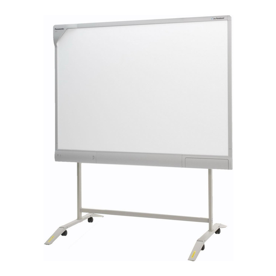
Stand is sold separately.
Electronic Board
(elite Panaboard)
UB-T780
Table of Contents

Related Manuals for Panasonic UB-T780


Summary of Contents for Panasonic UB-T780
- Page 1 Operating Instructions (For Basic Operations) Electronic Board (elite Panaboard) UB-T780 Model No. UB-T780 Stand is sold separately. Installation Manual Included (for qualified service personnel) • To assemble this unit, please refer to the Installation Manual on pages 31 through 50.
-
Page 2: Feature Highlights
Introduction Introduction Thank you for purchasing the Panasonic Electronic Board. For optimum performance and safety, please read these instructions carefully. Feature Highlights By connecting the elite Panaboard to a computer and using a projector to display the contents of the computer’s screen on the elite Panaboard, you can do the following. - Page 3 Introduction Things you should keep a record of Attach your sales receipt here For your future reference Date of purchase Serial number Dealer’s name Dealer’s address Dealer’s tel no. About the Operating Instructions There are 2 separate operating manuals for the elite Panaboard. For Basic Operations Instructions for connecting and operating the elite Panaboard, as (this document)
- Page 4 Introduction Federal Communications Commission Requirements For United States Only Note This equipment has been tested and found to comply with the limits for a Class A digital device, pursuant to part 15 of the FCC Rules. These limits are designed to provide reasonable protection against harmful interference when the equipment is operated in a commercial environment.
-
Page 5: System Requirements
Introduction System Requirements PC/AT or compatible with a CD-ROM drive Computer ® ® Intel Pentium 4 processor or later ® ® Windows 2000 SP4 / Windows XP / Windows Vista Operating System USB 2.0 Interface 256 MB or greater (Windows 2000 SP4) Memory (RAM) 512 MB or greater (Windows XP) 512 MB or greater (Windows Vista) - Page 6 Introduction Exemption of Liability Panasonic Communications Co., Ltd. is not responsible for accidents or injuries caused by, but not limited to, the following: Altering the device or improper installation construction. Using the device for purposes beyond its intended use. Earthquake, fire, flood, tidal wave, hurricane, lightning or other natural phenomena.
-
Page 7: Table Of Contents
Table of Contents For Your Safety ..................8 For Your Safety .........................8 For Users ...........................8 Safety Information (For United Kingdom Only) ............11 Precautions ........................12 Usage ......................13 Included Accessories .....................13 Names and Uses of the Parts ..................14 Connecting External Components ................17 Installing the elite Panaboard software ................19 Setting the Projector .......................20 Setting Your System (Calibration) .................21 Starting the elite Panaboard software and Performing Calibration ......22... -
Page 8: For Your Safety
For Your Safety For Your Safety For Users To prevent severe injury and loss of life, read this WARNING section carefully before using the unit to ensure proper and safe operation of your unit. The following graphic symbols are used in this Operating Instructions manual. - Page 9 For Your Safety Installation and Relocation Plug the power cord firmly into an AC out- let. Otherwise, it can cause fire or electric Have the unit installed, removed and dis- shock. posed of only by qualified service person- nel. Do not pull, bend, rest objects on, or chafe the power cord and plug.
- Page 10 For Your Safety Batteries that seem worn down or dam- CAUTION aged should not be used. Using worn down or damaged batteries may result in leaking. Power Do not charge, short, heat, break or throw in a fire, as it may result in the battery leak- When the unit is not used over an exten- ing, generating heat, or bursting.
-
Page 11: Safety Information (For United Kingdom Only)
Operating Safeguards cover is obtained. A replacement fuse cover can be purchased from your local Panasonic Dealer. If the unit is fallen down or damaged, turn If the fitted moulded plug is unsuitable for the socket the unit off and unplug the power cord. -
Page 12: Precautions
For Your Safety Precautions How to replace the fuse: Open the fuse About Using the Battery compartment with a If a battery is used improperly, the battery may leak, screwdriver and replace causing corrosion of the unit, or it may burst. To prevent the fuse. -
Page 13: Usage
Usage Included Accessories Check that all of the following items are included with your elite Panaboard. In the event that an item is missing, please contact your dealer. List of Accessories Power Cord USB Cable Software CD-ROM (3 m [9 ft. 10 in.]) (5 m [16 ft. -
Page 14: Names And Uses Of The Parts
Usage Names and Uses of the Parts Screen Front View Position Sensor Detects the position of the electronic pen. Do not block the sensor while operating the elite Panaboard. Screen Board Project the contents of a computer screen using a projector. - Page 15 Usage Notice • The elite Panaboard is designed exclusively for projector images. Do not write on the screen board with a white-board marker. If you write on the screen board with a white-board marker, you cannot erase it with a standard eraser. Use a commercially available melamine foam eraser to erase. Electronic Pen Penpoint When you push down on the penpoint, ultrasonic waves...
- Page 16 Usage • When operating the electronic pen, you will hear a buzzing sound due to the pen emitting ultrasonic waves for location detection. This sound does not have any negative effects for nearby people or devices. It will not cause electrical shocks. Inserting (Replacing) Batteries 1.
-
Page 17: Connecting External Components
Usage Connecting External Components Set the power switch to "O" (OFF), connect the power cord (included) to the elite Panaboard, and plug the power cord into an AC outlet. Rear Power Switch (ON) (OFF) Power Cord (Included) Power Cord • Plug the power cord into an outlet that is close to the elite Panaboard and in a location that is easy to unplug. - Page 18 Usage Connect the elite Panaboard to a computer using the USB cable (included). • elite Panaboard: Plug the B connector (smaller connector) into the elite Panaboard's USB port. Computer: Plug the A connector (larger connector) into a USB port on the computer. •...
-
Page 19: Installing The Elite Panaboard Software
When installation has finished, click [Finish]. • Restart your computer if you are prompted to do • The group [elite Panaboard] will be created in the [Panasonic] group in the program menu. • The following items will appear in the [elite Panaboard] group: –... -
Page 20: Setting The Projector
Usage Project the Image as a Rectangle Setting the Projector • Adjust the location of the projector to project at a Set up your projector as instructed below. right angle with the elite Panaboard. About Positioning the Image • When you are projecting an image, make sure that the edge of the projected image is at least 5 mm in.) from the screen frame. -
Page 21: Setting Your System (Calibration)
Usage Setting Your System (Cal- • If the image is projected trapezoidally, the position of the electronic pen may not be read correctly. ibration) Adjust the projector so that the projected image is a rectangle. Refer to your projector's documenta- tion for information on adjusting the projected im- About Calibration age. -
Page 22: Starting The Elite Panaboard Software And Performing Calibration
Usage Starting the elite Panaboard software and Performing Calibration Turn on the elite Panaboard. Connect the elite Panaboard to your computer with the USB cable. • Hold and press the electronic pen at a right • The elite Panaboard software starts angle to the screen board. -
Page 23: Uninstalling The Elite Panaboard Software
Select [Add or Remove Programs] from the Control Panel. • In Windows 2000, select [Add/Remove Programs], and in Windows Vista, select [Uninstall a program]. Select Panasonic elite Panaboard, then remove Follow the on-screen instructions. When uninstallation is complete, restart your computer. [Desktop Drawing Tool] •... -
Page 24: Viewing The Electronic Documentation
"Operating Instructions (For Software)". Turn on your computer and start Windows. Open "Operating Instructions (For Software)" from the Start menu. ([Start] ® [All Programs] ® [Panasonic] ® [elite Panaboard] ® [Operating Instructions for Software]) • The electronic documentation will be displayed. -
Page 25: Appendix
Appendix Daily Care When cleaning the elite Panaboard or inside the elite Panaboard, make sure to switch off the power and unplug the power cord from the AC outlet. Cleaning the elite Panaboard Replacing the Battery in the Electronic Pen When the charge in the battery in the electronic pen is low, the message, "The pen battery is low. -
Page 26: Replacing The Penpoint Of The Electronic Pen
Appendix Replacing the Penpoint of the Electronic Pen As the penpoint of the electronic pen becomes worn, a hole will appear in the penpoint. Continuing to use the electronic pen in this condition can cause damage to the screen or unsatisfactory operation, so replace the penpoint with a new one as soon as possible. -
Page 27: Troubleshooting
Appendix Troubleshooting When experiencing problems, please refer to the table below for possible solutions. If the problem persists, contact your dealer. Symptom Possible cause and solution See page Check that the power cord is properly plugged in. The LEDs do not light when →... - Page 28 Appendix Symptom Possible cause and solution See page The message "The pen bat- tery is low. Replace the bat- Replace the electronic pen's battery with a new one. tery soon." is displayed on the computer screen. Because the elite Panaboard is designed exclusively for projector Marks written with a images, you cannot erase the marks with a standard eraser.
-
Page 29: Specifications
5 mm ( in.) Electronic Pen Power LR03 (AAA alkaline dry cell battery) × 1 Electronic Pen Battery Life 30 hours (when used continuously at 25 °C [77 °F]) * When using Panasonic LR03 alkaline dry-cell batteries. Operating Instructions (For Basic Operations) -
Page 30: Optional Devices And Accessories
Appendix Optional Devices and Accessories Optional Device Stand KX-B061 Accessories Electronic Pen UE-608025 • To purchase separately sold items, contact your dealer. Operating Instructions (For Basic Operations) -
Page 31: Installation Manual
Installation Manual Installation Manual (for qualified service personnel) • Request assembly of the Electronic Board, stand and wall mounting from your dealer. • Before assembly and construction, read this section thoroughly. • When installing the elite Panaboard on a wall or on the stand, perform installation with 2 people. For Your Safety Notice To prevent severe injury and loss of life, read this... - Page 32 Installation Manual CAUTION After installing or moving the electronic board, lock the casters and set the fall-pre- vention extension legs. Locking the casters (Push this side) Push to lock If the unit is hung on a wall, confirm the wall must be capable of supporting at least the following weight.
-
Page 33: Included Accessories
Installation Manual Included Accessories Confirm that the following items are included with the elite Panaboard. Part Name Illustration Q’ty Remarks The illustration of the power cord is for the Uni- Power Cord ted States. The shape of (3 m [9 ft. 10 in.]) the plug may vary de- pending on country/area. - Page 34 Installation Manual Notice • Screws (8 count) for wall mounting are not included. Please purchase screws with a size of M6, appropriate for your type of wall (page 37). Operating Instructions (For Basic Operations)
-
Page 35: Wall Mounting Construction
Installation Manual Wall Mounting Construction Checking the Wall When mounting on a wall, consult with your building's owner, caretaker or construction manager to determine if the wall strength is sufficient to install the elite Panaboard. For safety, install the elite Panaboard only after thoroughly understanding the type of walls, the appropriate types of screws and the construction method (Page 37). -
Page 36: Installing The Wall Mounting Plates
Installation Manual Installing the Wall Mounting Plates Ensure that the wall is strong enough to support the elite Panaboard. Rated strength: greater than 1,324 N (135 kgf) Using the measuring tape and level, mark the 8 locations to insert the screws. 469.5 mm 813 mm 222.5 mm (8... -
Page 37: Wall Types And Installation Procedures
Installation Manual • Tighten the bolt so that it will not become loose. • When drilling the holes and installing the wall mounting plates, follow the procedure in "Wall Types and Installation Procedures" (page 37). Mount the elite Panaboard on the wall. See "Assembling the elite Panaboard"... - Page 38 Installation Manual Plasterboard walls Split-wing toggles (not included) are needed. Insert the bolt through the hole in the wall Split-wing toggle mounting plate and into the hole in the wall Plasterboard so that the arms of the split-wing toggle are horizontal.
-
Page 39: Stand Assembly (Sold Separately)
Installation Manual Stand Assembly (Sold Separately) Included Parts Check that the following parts are included with the stand (KX-BP061). Part Name Illustration Q'ty Stand Base Support Beam Cross Bar (A) Cross Bar (B) Screw (M6 ´ 45 mm [1 in.]) Two-wing Bolt (M5 ´... -
Page 40: Assembly Instructions
Installation Manual CAUTION Before assembly, be sure to lock the casters. Locking the casters (Push this side) Assembly Instructions Assemble the fall-prevention extension legs. Operating Instructions (For Basic Operations) - Page 41 Installation Manual Assemble the stand. Assemble with the holes toward the front. REAR Locking caster side (rear) Locking caster side (rear) FRONT Notice • Do not over-tighten the screw ( ). (Doing so can warp the support beams.) • Assemble the stand so that the locking casters are on the rear side. Operating Instructions (For Basic Operations)
- Page 42 Installation Manual Pull the fall-prevention extension legs down. Note • When folding back the fall-prevention extension legs, release the lock as follows ( Mount the elite Panaboard. See "Assembling the elite Panaboard" (For Mounting on a Stand (Sold Separately) ® page 47). Operating Instructions (For Basic Operations)
-
Page 43: Assembly Instructions
Installation Manual Assembly Instructions Preparing for Removing the elite Panaboard from Its Packaging Open the box, remove the accessory box & packing foam and open the plastic sheet of the elite Panaboard. Shipping Box Accessory Box Contents ] ....Power Cord •... -
Page 44: Assembling The Elite Panaboard
Installation Manual Assembling the elite Panaboard Pull the loose end of the cable tie to tighten it, and install the power cord depending on the For Wall Mounting location of the outlet, as illustrated in the following diagrams. Loosely wrap the power cord with the cable tie, •... - Page 45 Installation Manual Hang the elite Panaboard on the wall mounting Remove the 4 latches from the board plates with the screw heads. attachment by pushing them towards the rear. Latches Remove the lower frame cover. Remove the left and right screws, and then remove Board Attachment the lower frame cover from the main unit of the elite Fasten to the wall.
- Page 46 Installation Manual How to Attach the Lower Frame Cover Pull the lower frame cover ( While keeping the rear section of the lower Holding the lower frame cover with both frame cover against the rear of the board, push hands, slide it into the guides on both sides. the lower frame cover up into the rear of the board ( Push the lower frame cover backward (...
- Page 47 Installation Manual For Mounting on a Stand (Sold Sep- Wipe the screen board surface. Gently wipe the screen board surface with a soft, arately) moist cloth. Attach the power cord. • Connect the power cord to the elite Panaboard before installing on the stand. Power Cord Notice •...
- Page 48 Installation Manual Hang the elite Panaboard on the stand with the • When installing the elite Panaboard on the screw heads. stand, you can adjust its height to 4 different levels. When changing the height, remove the left and right screws from the back of the elite Panaboard, and securely insert them at the desired height.
-
Page 49: Confirming The Elite Panaboard Operation
Installation Manual Confirming the elite Panaboard Operation After assembling the elite Panaboard, confirm that it operates properly by following the procedure below. Checkpoints Action Operation Measure 1 Turn on the power. Green LED lights. (Normal operation) Green LED does not light, or Check the power cord. -
Page 50: Repackaging
Installation Manual Repackaging To repackage the elite Panaboard, perform steps in "Assembling the elite Panaboard" (For Wall Mounting ® page 44, For Mounting on a Stand (Sold Separately) ® page 47) in reverse. Package the unit as depicted in the diagram in "Preparing for Removing the elite Panaboard from Its Packaging" (page 43). Notice •... - Page 51 Notes Operating Instructions (For Basic Operations)
- Page 52 For information of Compliance with EU relevant Regulatory Directives, Contact to Authorised Representative: (For EU only) Panasonic Testing Centre Panasonic Marketing Europe GmbH Winsbergring 15, 22525 Hamburg, Germany Panasonic Global Site http://panasonic.net/ © 2007 Panasonic Communications Co., Ltd. All Rights Reserved.