Table of Contents
Quick Links
See also:
Instruction Manual
INSTRUCTION MANUAL
BEDIENUNGSANLEITUNG
MANUEL D'INSTRUCTIONS
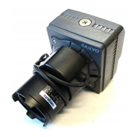
COLOUR CCD camera
CCD-Farbkamera
Caméra CCD COULEUR
CCD
About this manual
Before installing and using the camera, please read this
manual carefully. Be sure to keep it handy for later reference.
Über diese Bedienungsanleitung
Lesen Sie bitte vor der Montage und dem Inbetriebnehmen
der Kamera zuerst diese Bedienungsanleitung sorgfältig
durch und bewahren Sie sie zum späteren Nachschlagen auf.
VCC-5775P
A propos de ce manuel
Avant d'installer et d'utiliser la caméra, veuillez lire ce
manuel attentivement. Gardez-le à portée de main pour
toute référence ultérieure.
Table of Contents

Related Manuals for Sanyo VCC-5775P


Summary of Contents for Sanyo VCC-5775P
- Page 1 VCC-5775P INSTRUCTION MANUAL BEDIENUNGSANLEITUNG MANUEL D’INSTRUCTIONS COLOUR CCD camera CCD-Farbkamera Caméra CCD COULEUR About this manual A propos de ce manuel Before installing and using the camera, please read this Avant d’installer et d’utiliser la caméra, veuillez lire ce manual carefully. Be sure to keep it handy for later reference.
-
Page 2: Table Of Contents
Depending on the conditions of use, installation CONTENTS and environment, please be sure to make the appropriate settings and adjustments. If you PRECAUTIONS ......3 need help with installation and/or settings, please consult your dealer. PARTS NAMES ......5 MOUNTING THE LENS....7 CONNECTIONS...... - Page 3 FEATURES • Built-in interline transfer method 1/3" CCD, approx. 470,000 picture elements • Low smear, anti-blooming, low lag, no burning and no geometric distortion using the CCD solid state image device. • 100% solid state components giving excellent immunity to shock and vibration •...
-
Page 4: Precautions
If water or a liquid gets inside the camera, disconnect the power cord immediately, and consult your dealer (or a Sanyo Authorized Service Centre). Be careful to protect the camera from rain, sea water, etc. English... - Page 5 PRECAUTIONS Protect from high temperatures Cleaning • Do not install close to stoves, or other heat Dirt can be removed from the cabinet by generating devices, such as spotlights, etc., or wiping it with a soft cloth. To remove stains, where it could be subject to direct sunlight, as that wipe with a soft cloth moistened with a soft could cause deformation, discoloration or other...
-
Page 6: Parts Names
PARTS NAMES 1 Camera mounting screw hole CAUTION: When installing the camera, select a location that can support the total weight of the camera and accessories. 2 Electronic iris function switch (EI OFF/EI ON) 3 Sync switch (INT/L-L) INT (Internal sync) position L-L (Line lock) position 4 Line phase adjustment volume (LINE PHASE) 5 Lens iris level volume (LEVEL) - Page 7 PARTS NAMES 7 Flange-back lock screw 8 CS mount ring 9 Lens mount cap The cap is installed to protect the lens mount section. Remove the lens mount cap before installing a lens. F Video output connector (VIDEO OUT: BNC type) Connect this connector to a device such as a VCR or monitor with a VIDEO IN connector.
-
Page 8: Mounting The Lens
MOUNTING THE LENS Please use a DC type auto-iris lens (sold separately). Checking the lens mount Do not use lense with a length L more than 5 mm. If not, that may damage the camera and prevent proper installation. Remove the lens mount cap from the camera. Install the auto-iris lens. - Page 9 MOUNTING THE LENS Rewiring the lens cable in the lens iris plug Prepare the lens cable. Cut the cable at the plug, then remove approx. 8 mm of the cable sheath and strip about 2 mm from each wire. Install the lens iris plug. Solder the cable to the pins following the correct pin layout (refer to the table and illustrations), then close the plug cover.
-
Page 10: Connections
CONNECTIONS Basic connection for monitoring or recording Note: The polarities for the 24 V AC and the 12 V DC input connectors are indicated on the rating label found on the unit back panel. AC 24 V ~ ~ DC 12 V + – Push to insert the cable. - Page 11 CONNECTIONS The peripheral devices (VCR, monitor, lens, Insert the plug of this power supply into etc.) and cables are sold separately. a wall outlet. Make the video signal connection Adjust the picture on the monitor using the between the camera and the monitor or Brightness and Contrast controls.
-
Page 12: Flange-Back Adjustment
FLANGE-BACK ADJUSTMENT CS mount If the pick-up surface is not correctly positioned with relation to the lens ring focal point, the picture will be out of focus (in particular when using auto-iris power zoom lenses, sold separately). If that is the case, adjust the flange-back position as described below. -
Page 13: Settings
SETTINGS Line phase adjustment When using a camera switcher to connect 2 cameras or more to one monitor, there may be a vertical roll of the images when switched. In such a case, set as described below. Set the Sync switch to the L-L position. (Monitor) Switch the display on the monitor from camera 1 to camera 2. - Page 14 SETTINGS Lens iris adjustment If using a DC type auto-iris lens, you will need to set the LEVEL volume when shooting in the conditions described below. Counterclockwise: To decrease the brightness Clockwise: To increase the brightness • If shooting simultaneously in a dark room and through a bright window.
- Page 15 SETTINGS • If conditions are outside the electronic iris EI (Electronic iris) function setting operation range or more than the maximum Under normal conditions, set the EI switch to brightness, it will cause saturation of the the EI OFF position and use an auto-iris lens. CCD.
-
Page 16: Troubleshooting
Before taking the camera for repairs, please check below to make sure that the camera is used correctly. If it still does not perform correctly, please consult your dealer or a Sanyo Authorized Service Centre. No picture on the monitor screen SERVICE •... -
Page 17: Specifications
SPECIFICATIONS Scanning system: PAL standard Electronic iris range: (625 TV lines, 25 frames/sec.) 1.4 lux to 70,000 lux (F 1.2, lens) 2.0 lux to 100,000 lux (F 1.4, lens) Interlace: 2:1 interlace Flange-back: 12.5 mm ± 0.5 mm Image device: 1/3 inch solid state image device CCD White balance: ATW Picture elements: 798 (H) x 584 (V) Lens mount: CS mount... - Page 18 SPECIFICATIONS Dimensions: mm Features and specifications are subject to change without prior notice or obligations. English...
-
Page 19: Accessories
ACCESSORIES 1C mount adaptor (5 mm) ......1 pc. The C mount adaptor must be used to be able to install a C mount lens on the camera. 2Lens iris plug (4-pin).........1 pc. English...