Table of Contents
Quick Links
Table of Contents

Related Manuals for Panasonic SJ-MR200


Summary of Contents for Panasonic SJ-MR200
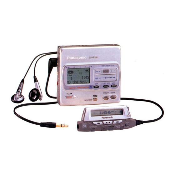
- Page 1 ORDER No.AD0009165C8 Portable MD Recorder SJ-MR200 MD unit: RAE1630Z-M Mechanism Series Colour (S)....Silver Type (W)....White Type Areas EB....Great Britain. EG....Europe. GH....Hong Kong. SPECIFICATIONS Specifications...
- Page 2 Play time Record time About 15 hours About 7 hours Rechargeable: About 21 hours About 3 hours Panasonic alkaline: About 38 hours About 15 hours Both together: Charger AC 220 V (GH) / AC220-230 V (EG) / Input: AC 230-240V (EB), 50/60 Hz 8W...
- Page 3 Notes: - The play time may be less depending on the operating conditions. - Specifications are subject to charge without notice. Weight and dimensions are approximate. 2000 Matsushita Electric Industrial Co., Ltd. All rights reserved. Unauthorized copying and distribution is a violation of law. 1.
-
Page 4: Handling Precautions For Traverse Deck
3. Operating Instructions 4. Handling Precautions for Traverse Deck The laser diode in the traverse deck (optical pickup) may break down due to potential difference caused by static electricity of clothes or human body. So, be careful of electrostatic breakdown during repair of the traverse deck (optical pickup). 4.1. - Page 5 vibration, or other types of rough handling. 2. In order to prevent static electricity damage to the laser diode, use a short pin or similar tool to short the optical pickup’s flexible circuit boards after they have been disconnected from the main circuit board.
-
Page 6: Operation Checks And Component Replacement Procedures
(as shown in Fig. 4 Caution The static electricity of your clothes will not be grounded through the wrist strap. So, take care not to let your clothes touch the traverse deck (optical pickup). Fig. 3 Fig. 4 5. Operation Checks and Component Replacement Procedures - This section describes procedures for checking the operation of the major printed circuit boards and replacing the main... - Page 7 - Check the main P.C.B. (A side) as shown below. [Checking for the main P.C.B. (B side)] - Each parts on main P.C.B. (B side) can not be checkesd directly, however, for the checking of main component parts on P.C.B., refer to the “Checking procedures of main components parts on the main P.C.B.
- Page 8 5.2. Replacement for the intermediate cabinet - Follow the (Step 1) - (Step 3) of item 5.1. 5.3. Replacement for the open knob and lock unit - Follow the (Step 1) - (Step 3) of item 5.1.
- Page 9 - Follow the (Step 1) - (Step 3) of item 5.2. 5.4. Replacement for the traverse motor - Follow the (Step 1) - (Step 3) of item 5.1.
- Page 10 5.5. Replacement for the LCD - Follow the (Step 1) - (Step 3) of item 5.1. - Follow the (Step 1) - (Step 3) of item 5.2.
- Page 12 5.6. Replacement for the lift motor - Follow the (Step 1) - (Step 3) of item 5.1. - Follow the (Step 1) - (Step 3) of item 5.2. - Follow the (Step 1) of item 5.5.
- Page 13 5.7. Replacement for the optical pickup - Follow the (Step 1) - (Step 3) of item 5.1. - Follow the (Step 1) - (Step 3) of item 5.2. - Follow the (Step 1) - (Step 4) of item 5.4. - Follow the (Step 1) of item 5.5.
- Page 16 6. Measurements and Adjsutments Note: After replacing the main components (optical pickup or traverse motor, etc.) of mechanism unit block, change to the adjust mode, and then perform the “ROM/RAM auto-adjustment”. 6.1. Instruments to prepare 1. Playback-only disc (Test disc RFKV0006) 2.
- Page 17 4. Remote controller 6.2. Laser power adjustment, Playback-only disc/magneto-optical disc automatic adjustment 6.2.1. Enter the adjustment mode 1. Set the battery and connect the remote controller. 2. Turn off the power, and switch main unit’s HOLD switch off. 3. Press the VOL+, VOL-, , and buttons on the remote controller within two seconds.
- Page 18 Adjustment mode Display Laser power adjustment Magneto-optical disc automatic adjustment Playback-only disc automatic adjustment EFM jitter meajurement Record inspection REC jitter meajurement Magneto-optical disc automatic adjustment value check Playback-only disc automatic adjustment value check Error rate measurement (double velocity) AD read result confirmation ROM collection check sum DRAM check Reliability test...
- Page 19 staticelectricity generated in your clothes or body. Be especially careful with the static electricity. 6.2.2.2. Adjustment Procedure 1. Have “ T1 EX ” indicated on display, and move the optical pickup to the most inside (only when a MD cartridge type laser power meter is used).
- Page 20 RLDA ” in the LCD). Specified range (read power): 600 W±10% or lower 8. Perfome the light power adjustment. Set the light power at 4.55mW by using VOL+ and VOL- key of the remote controller. If at this time the amperage between TP405 and TP406 (laser current) is 70mA or higher, it is conceivable that theoptical pickup is defective.
- Page 21 2. Set the full-recorded magneto-optical disc with the prevention erase situation. 3. Press the PLAY key of the remote controller (“ T2 EX ” changes to “ 1AADJ ” on the LCD, adjustment is started.). 4. If it has been finished normally, “ 1ADDJ ” changes to “ 1AOK ” on LCD.
-
Page 22: Remote Control
OFF, press the VOL+, VOL-, , and buttonson the remote controller within two seconds. (as shown in Fig. 5 3. When entering the main unit’s key check mode, “ KEY EX ” will be displayed on the LCD of main unit and “ T KEX ” will be displayed on the LCD of remote controller. -
Page 23: Troubleshooting Guide
Display position Main unit’s keys 4th. letter DISPLAY, PLAYMODE, EQ 5th. letter Flat pad lower rank 3 key 6th. letter Flat pad upper rank 3 key 9. Upon detection of all keys, “ 000 ” is shown on the right side of LCD of the remote control. - Page 32 8. Checking Procedures of Main Components Parts on the Main P.C.B. (B side) As it cannot meajure the mechanism side of MAIN P.C.B. directly, refer to the table shown below for the criterion in the time of repairing or checking.
- Page 33 Part No. Function Symptom Check point Result and measure Circuit IC304 C0DBAGZ00006 DC-DC Recording is Confirm the If voltage at TP137 converter / 3.5V impracticable. voltage of IC403 normal and voltage / Power IC for (pin 14) or (TP137) IC501 is unusual, magnetic head IC501 and switch Confirm the...
-
Page 34: Schematic Diagram Notes
fails to move up/down normally (Due to trouble of the magnetic head or trouble of the magnetic head up/down motor)or the magnetic head P.C.B. is out of position or a foreign matter has mixed in or for some other reason. In such a case, check the peripheral parts of the magnetic head, repair or replace defective parts with normal ones. -
Page 35: Schematic Diagram
Components identified by mark have special characteristics important for safety. Furthermore, special parts which have purpose of fire-retardant (resistors), high-quality sound (capacitors), low-noise (resistors), etc. are used. When replacing any of components, be sure to use only manufacture's specified parts shown in theparts list. Caution! IC and LSI are sensitive to static electricity. - Page 36 Mark Function Division CENVD D signal det. capacitor input terminal Laser amp output terminal APCPD Photo diode light quantity det. input terminal LD IN Laser amp reverse input terminal APC REF APC amp reference voltage input terminal TEMP IN Temperature sensor amp input terminal TEMP Temperature sensor amp...
- Page 37 Mark Function Division CBD O BDO detection capacitor connection terminal (Connected to GND through capacitor) OFT O Off track detection signal output terminal — GND terminal OFT IN Off track detection signal input terminal Power supply terminal (+ 27 NRFDET/ NRFDET/off track signal / OFTR output terminal...
- Page 38 Mark Function Division 44 / A / ~ / D Main beam A~D signal input terminal CENVC Beam E signal detection capacitor input terminal 15.2. IC101 (M66616RB2) : ATRAC ENCORDER/DECORDER, SERVO SIGNAL PROCESSOR Mark Function Division ADIP ADIP FM signal input terminal Lens position signal input terminal...
- Page 39 Mark Function Division TRDP Tracking drive (+) PWM signal output terminal TRDM Tracking drive (-) PWM signal output terminal FODP Focus drive (+) PWM signal ouutput terminal FODM Focus drive (-) PWM signal/ focus, tracking ON/OFF signal output terminal SPDP Spindle drive (+) PWM signal output terminal Spindle drive (-) PWM...
- Page 40 Mark Function Division SSDR MSP/MDA,I/F read data output terminal MDISY Leader synchronous signal output SCTSY ADIP synchronous noise output terminal SGSYNC Frame synchronous signal output terminal Power supply terminal — Power supply terminal for I/ O pad — GND terminal FS384 384 Fs output terminal Bit clock output terminal...
- Page 41 Mark Function Division — Not used, connected to — Not used, connected to — Not used, connected to 82 EXSYSCK External system clock input terminal (Not used, connected to GND) Power supply terminal Crystal oscillator input terminal (F=16.9344MHz) Crystal oscillator output terminal (F=16.9344MHz) VDss2 —...
- Page 42 MOTOR DRIVE, SPINDLE MOTOR DRIVE, ROTARY DETECTOR Mark Function Division SPWIN Roter position detect comparater(W) input terminal SPCOM Spindle motor coil center input terminal EXTCLK Not used, open — Charge pump capacitor 1(+) connect terminal — Charge pump capacitor 1(-) connect terminal —...
- Page 43 Mark Function Division ASGND — GND terminal STHB H1, H2 bridge mute input terminal STALL Standby input terminal PW1VM Power supply terminal PW1OUT Hlaf bridge 1 output terminal / (Not used, open) PWPG — GND terminal PW2OUT Half bridge 2 output terminal PW2VM Power supply terminal...
- Page 44 Mark Function Division BRK- Brake comparater- input terminal BRK+ Brake comparater+ input terminal Power supply terminal Power supply terminal SP VM1 Half bridge 1 input terminal SP U Spindle motor coil (U) output terminal SP PG1 — GND terminal SP V Spindle motor coil (V) output terminal SP VM2...
- Page 45 Mark Function Division OSC2 System clock input terminal (f=10.02MHz) OSC1 System clock output terminal (f=10.02MHz) — GND terminal Sub clock input terminal (Not used, connected to GND) Sub clock output terminal (Not used, open) MMOD — Memory mode select input terminal (Connected to GND) LCD driver data output...
- Page 46 Mark Function Division SCTSY ADIP/sub A synchronize signal from IC101 input terminal CFSYNC MDA synchronize signal from IC101 input trminal (11.6ms pulse) 35 OPENSW Disc cover open/close switch det. input terminal (“H”:open, “L”:close) LCD driver data output DATA terminal — —...
- Page 47 Mark Function Division JITTER Connected to power supply through resistor HOLD HOLD switch input terminal (“H”:OFF, “L”:ON) 56 DCINDET DC IN det. input terminal MIC DET Mic det. input terminal INSEL INPUT select det. input terminal FPOUT1 Flat pad A output terminal / JOGA FPOUT2 Flat pad B output terminal...
-
Page 48: Replacement Parts
Mark Function Division 4ch driver standby output terminal STBY2 FD/TR coil power supply control output terminal — Not used, open MSP reset output terminal 16. Caution in Use of Rechargeable Battery Ass'y - Take Rechargeable Battery Ass’y out of Battery Carrying Case and use it. -
Page 49: Replacement Parts List
18. Replacement Parts List Notes: *Important safety notice: / Components identified by mark have special characteristics important for safety. / Funrthermore, special parts which have purposes of fire-retardant (resistors), high-quality sound (capacitors),low-noise (resistors), etc. are used. / When replacing any of components, be sure to use only manufacture’s specified parts shown in the parts list. - Page 50 Ref. No. Part No. Part Name & Description Remarks RGU1915-S1 OPERATION BUTTON RGU1915-D2 OPERATION BUTTON RHQ0083-S SCREW RJB2280A OPERATION FPC RMN0613 LCD HOLDER RMQ0916 TAPE RMZ0533 INSULATING SHEET RXM0072 LINK UNIT RYF0560-S DISC COVER RYF0560-W DISC COVER RGV0266-S REC KNOB RMA1378 REC LEVER XQN14+B2FC...
- Page 51 Ref. No. Part No. Part Name & Description Remarks 17-28 RMM0230 EJECT ROD A 17-29 RMQ0958-2 17-30 RXG0050 TRANSFER GEAR 17-31 RXK0318 HOLDER UNIT 17-32 RXM0071 EJECT ROD B 17-33 XQN14+A12FC SCREW 17-34 RMX0194 SHEET RMX0190 SPACER RMG0534-K SHEET RMX0187 HOLDER SPACER RFKFHFAZ01EM RECHARGEABLE BATT.ASS'Y...
- Page 52 Ref. No. Part No. Part Name & Description Remarks ECUV0J474KBV 6.3V 0.47U F1H0J474A002 ECUE1E332KBQ 25V 3300P F1G1E3320001 C101 RCST0GZ106RG 4V 10U F3E0G106A002 C102 ECUENA104KBQ 10V 0.1U F1G1A104A014 C104 ECUE1H102KBQ 50V 1000P F1G1H102A457 C105 ECUE1C103KBQ 16V 0.01U C107 RCST0GZ106RG 4V 10U F3E0G106A002 C108 ECUENA104KBQ...
- Page 53 Ref. No. Part No. Part Name & Description Remarks C425,26 ECUENC273KBQ 16V 0.027U F1G1C273A004 C427 ECUV0J334KBV 16V 0.33U C432-35 ECUE1C103KBQ 16V 0.01U C441 RCST0GZ106RG 4V 10U F3E0G106A002 C442 ECUENA104KBQ 10V 0.1U F1G1A104A014 C443 ECUENA473KBQ 10V 0.047U F1G1A473A014 C444 ECUENA104KBQ 10V 0.1U F1G1A104A014 C445 ECUE1H150JCQ...
- Page 54 Ref. No. Part No. Part Name & Description Remarks CP803 K1MN05B00042 CONNECTOR(5P) MA2S111TX DIODE MA2S11100L D301 MA133TX DIODE MA3S13300L D303-05 B0JCMC000006 DIODE D401,02 ZHCS1006TA DIODE B0JCLG000001 D403,04 MA133TX DIODE MA3S13300L D501,02 MA741WATX DIODE MA3J741D0L AN8772FHKEBV IC101 MN66616RB2 IC102 MNA7400CWA1T IC201 TA2131FL IC301 NJU7015RTE1...
- Page 55 Ref. No. Part No. Part Name & Description Remarks RPF0257-1 PROTECTION BAG RPQ1004-1 TRANSPORT SPACER PCB1 REP3036A-M REC.HEAD P.C.B. (RTL) PCB2 REP3038B-M MAIN P.C.B. (RTL) PCB3 REP3039A-S OPERATION P.C.B. (RTL) 2SB1295-6-TB TRANSISTOR B1ADKB000001 2SB1462STX TRANSISTOR 2SB14620SL Q202 2SB1295-6-TB TRANSISTOR B1ADKB000001 Q203 B1ABDF000001 TRANSISTOR...
- Page 56 Ref. No. Part No. Part Name & Description Remarks R114 ERJ2GEJ473X 1/4W 47K ERJ2RMJ473X R201 ERJ2GEJ104X 1/4W 100K ERJ2RMJ104X R202 ERJ2GEJ221X 1/4W 220 ERJ2RMJ221X R203 ERJ2GEJ102X 1/4W 1K ERJ2RMJ102X R204 EXB24V225JX 1/16W 2.2M R205 ERJ2GEJ222X 1/4W 2.2K ERJ2RMJ222X R206 EXB24V100JX 1/16W 10 R207 ERJ2GEJ471X...
-
Page 57: Cabinet Parts Location
Ref. No. Part No. Part Name & Description Remarks R518 EXB28V104JX 1/32W 100K R602 ERJ2GEJ5R6X 1/4W 5.6 ERJ2RMJ5R6X R603 EXB24V123JX 1/16W 12K R604 ERJ2GEJ470X 1/4W 47 ERJ2RMJ470X R605 EXB28V470JX 1/32W 47 R701 ERJ2GEJ102X 1/4W 1K ERJ2RMJ102X R702 ERJ2GEJ103X 1/4W 10K ERJ2RMJ103X R703 EXB24V104JX... - Page 58 20. Packaging...
- Page 59 Printed in Japan (H000900000) SW/HH...