Panasonic SJ-MR220 Service Manual
Hide thumbs
Also See for SJ-MR220:
- Operating instructions manual (47 pages) ,
- Operating instructions manual (53 pages) ,
- Schematic diagrams (8 pages)
Table of Contents
ORDER No.AD0109126C8
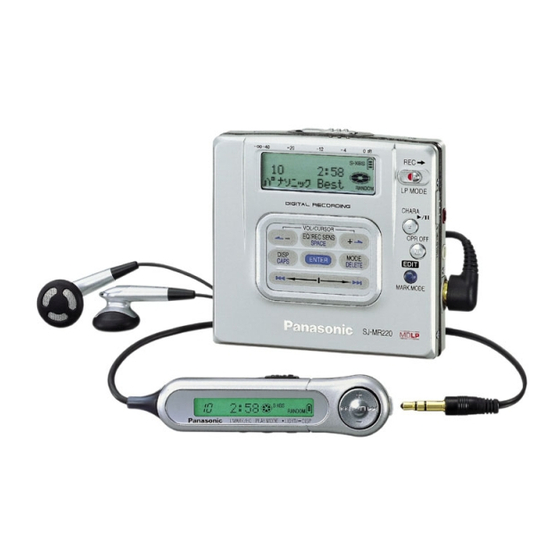
Portable MD Recorder
SJ-MR220
MD unit: RAE1640Z-M Mechanism Series
Colour
(S)...................Silver Type
(W)..................White Type [(GH) area only.]
Areas
EB...................Great Britain.
EG...................Europe.
GCS................Singapore, Malaysia.
GH...................Hong Kong.
1
Table of Contents

Related Manuals for Panasonic SJ-MR220


Summary of Contents for Panasonic SJ-MR220
- Page 1 ORDER No.AD0109126C8 Portable MD Recorder SJ-MR220 MD unit: RAE1640Z-M Mechanism Series Colour (S)....Silver Type (W)....White Type [(GH) area only.] Areas EB....Great Britain. EG....Europe. GCS....Singapore, Malaysia. GH....Hong Kong.
-
Page 2: Specifications
SPECIFICATIONS Specifications Audio MiniDisc digital audio system System: Semiconductor laser (=780 nm) Laser: 44.1 kHz Sampling frequency: Adaptive Transform Acoustic Coding Coding: (ATRAC / ATRAC3) 2 (left and right, stereo) No. of channels: 1 (monaural) 20 Hz-20 kHz (+0 dB, -8dB) Frequency response: Below measurable limit Wow and flutter:... - Page 3 About 5.5 hours Normal: About 15 hours About 8 hours LP2: About 17 hours About 9.5 hours LP4: Panasonic alkaline About 42 hours About 19 hours Normal: About 54 hours About 26 hours LP2: About 62 hours About 34 hours...
- Page 4 1. Accessories - Rechargeable battery..........1pc. (RP-BP62EYD) - External battery case..........1pc. (RFA1537-S2) - Carrying case............1pc. (RFC0069-H) - Stereo earphones..........1pc. (L0BAB0000162) - Connection cable..........1pc. (K2KA39B00001) For EB area - AC adaptor.............1pc. (RFEA003B-S) For EG, GCS areas - AC adaptor.............1pc. (N0JCAD000001) For GH area - AC adaptor.............1pc.
-
Page 5: Handling Precautions For Traverse Deck
3. Operating Instructions 4. Handling Precautions for Traverse Deck The laser diode in the traverse deck (optical pickup) may break down due to potential difference caused by static electricity of clothes or human body. So, be careful of electrostatic breakdown during repair of the traverse deck (optical pickup). - Page 6 4.1. Handling the traverse deck (optical pickup) 1. The traverse deck (optical pickup) is an extremely high-precision construction and must not be subjected to impact, excessive vibration, or other types of rough handling. 2. In order to prevent static electricity damage to the laser diode, use a short pin or similar tool to short the optical pickup’s flexible circuit boards after they have been disconnected from the main circuit board.
-
Page 7: Operation Checks And Component Replacement Procedures
1. Human body grounding Use the anti-static wrist strap to discharge the static electricity from your body. (as shown in Fig. 2. Work table grounding Put a conductive material (sheet) or steel sheet on the area where the traverse deck (optical pickup) is placed, and ground the sheet. (as shown in Fig. - Page 8 - For reassembly after operation checks or replacement, reverse the respective procedures. Special reassembly procedures are described only when required. - After replacing the main components (optical pickup or traverse motor, etc.) of mechanism unit block, change to the adjust mode, and then perform the “ROM/RAM auto-adjustment”.
- Page 9 [Checking for the main P.C.B. (B side)] - Each parts on main P.C.B. (B side) can not be checkesd directly, however, for the checking of main component parts on P.C.B., refer to the “Checking procedures of main components parts on the main P.C.B.
- Page 10 5.3. Replacement for the open knob and lock unit - Follow the (Step 1) - (Step 3) of item 5.1. - Follow the (Step 1) - (Step 3) of item 5.2. 5.4. Replacement for the traverse motor - Follow the (Step 1) - (Step 3) of item 5.1.
- Page 12 5.5. Replacement for the LCD - Follow the (Step 1) - (Step 3) of item 5.1. - Follow the (Step 1) - (Step 3) of item 5.2.
- Page 14 5.6. Replacement for the lift motor - Follow the (Step 1) - (Step 3) of item 5.1. - Follow the (Step 1) - (Step 3) of item 5.2. - Follow the (Step 1) of item 5.5.
- Page 15 5.7. Replacement for the optical pickup - Follow the (Step 1) - (Step 3) of item 5.1. - Follow the (Step 1) - (Step 3) of item 5.2. - Follow the (Step 1) - (Step 4) of item 5.4. - Follow the (Step 1) of item 5.5.
- Page 17 5.8. Replacement for the spindle motor - Follow the (Step 1) - (Step 3) of item 5.1. - Follow the (Step 1) - (Step 4) of item 5.4. 6. Measurements and Adjsutments Note: After replacing the main components (optical pickup or traverse motor, etc.) of mechanism unit block, change to the adjust mode, and then perform the “laser power adjustment”, “off-set auto- adjustment”...
- Page 18 2. Commercially available recordable disc (fully recorded with music) (magneto-optical disc) 3. Laser power meter (LE8010 or compatible meter) 4. Remote controller Note: For use of MD cartridge type laser power meter, remove the intermediate cabinet before perform the laser power adjustment (as for the method of disassembly, refer to “5. Operation checks and main component replacement procedures”.).
- Page 19 4. When the adjustment mode is activated, “T0E1” or “T0E2” will be displayed on the LCD of remote controller and unit [(EB, EG, GCS) areas are displayed only unit]. After “T0E1” or “T0E2” is displayed, select the desired adjustment item with the button or button of the remote controller.
- Page 20 6.2.2. Laser Power Adjustment Adjust each laser power: read power for reading (play) and write power for writing (record). 6.2.2.1. Set the Unit to the Adjustment Mode Cautions About handling the optical pickup and the magnetic head. - The optical pickup and the magnetic head are structured precisely; therefore, they are very fragile.
- Page 21 Fig. 7 Fig. 8 Fig. 9 3. Press the PLAY key of the remote controller (“T0**” changes to “LD” of the LCD). 4. Press the key of the remote controller (“LD” changes to “LP” of the LCD). 5. Perform the read power adjustment. Set the light power at 600 W±...
- Page 22 Proceeding on to the subsequent adjustment procedure with the read power exceeding 600 W±10% will result in damage to the optical pickup. 6. Press the key of the remote controller (“LP” changes to “RLDA” in the LCD). Specified range (read power): 600 W±10% or lower 7.
- Page 23 2. Set the full-recorded magneto-optical disc with the prevention erase situation. 3. Press the PLAY key of the remote controller (“T2**” changes to “1AADJ” on the LCD, adjustment is started.). 4. If it has been finished normally, “1ADDJ” changes to “00OK” or “10OK”...
-
Page 24: Remote Control
1. Set the battery and connect the remote controller. 2. Turn off the power. Then, with the main unit’s HOLD switch at OFF, press the VOL+, VOL-, , and buttons on the remote controller within two seconds. (as shown in Fig. -
Page 25: Troubleshooting Guide
remote control. / Keys to be pressed are not in order. / When the 3 keys apportioned to the respective letters as shown below are all OK, “0” is displayed. Display position Main unit’s keys Flat pad lower rank 3 keys 4th. - Page 34 8. Checking Procedures of Main Components Parts on the Main P.C.B. (B side) As it cannot meajure the mechanism side of MAIN P.C.B. directly, refer to the table shown below for the criterion in the time of repairing or checking.
- Page 35 Part No. Function Symptom Check point Result and measure Circuit IC304 C0DBAGZ00006 DC-DC converter Recording is Confirm the If voltage at TP137 / 3.5V / Power impracticable. voltage of IC902 normal and voltage IC for magnetic (pin 14) or (TP137) IC501 is unusual, check head driver IC501 and switch...
-
Page 36: Schematic Diagram Notes
“F15”---This indication appears when the Down switch fails to turn ON since the magnetic head fails to move up/down normally (Due to trouble of the magnetic head or trouble of the magnetic head up/down motor) or the magnetic head P.C.B. is out of position or a foreign matter has mixed in or for some other reason. -
Page 37: Schematic Diagram
errors in the voltage values, depending on the internal impedance of the DC circuit tester. No mark: MD STOP ( ): MD play [1kHz, L+R, 0dB] Important safety notice: Components identified by mark have special characteristics important for safety. Furthermore, special parts which have purpose of fire-retardant (resistors), high-quality sound (capacitors), low-noise (resistors), etc. - Page 38 Mark Function Division Laser amp output terminal LD IN Laser amp reverse input terminal APCPD Photo diode light quantity det. input terminal APC REF APC amp reference voltage input terminal ARFO RF amp. output terminal — Not used, open EQ IN EQ input terminal —...
- Page 39 output terminal Mark Function Division 23,24 Not used, open — ADIP ADIP signal output terminal Not used, open — NREC REC/PLAY select signal input terminal RFSWHL Reflect H/L select signal input terminal 29 RFSWPG Pit / group select signal output terminal GND terminal —...
- Page 40 Mark Function Division Main beam C signal input terminal 15.2. IC101 (M66621ARG) : ATRAC ENCORDER/DECORDER, SERVO SIGNAL PROCESSOR Mark Function Division Test input terminal (Not used, connected to GND) APCD Laser power setting PWM output terminal RFSWPG Pit / group setting signal output terminal RFSWHL High / low reflection...
- Page 41 Mark Function Division TVDP/ Traverse (+) drive signal / stepper drive signal 1 STPO1 output terminal SBCK/ Sub code Q clock for resistor / stepper drive STPO2 signal 2 output terminal SUBC/ Sub code Q / stepper status 0 input terminal STPI0 BLKCK/ Sub code block clock...
- Page 42 Mark Function Division SCTSY ADIP synchronous noise output terminal SSDR System control read data output terminal SSDW System control write data input terminal SSCK System sift clock signal input terminal SELAD System control address signal select input terminal MONI1 Monitor 1 output terminal (Not used, open) MONI2 Monitor 2 output terminal...
- Page 43 Mark Function Division Servo A/D converter input terminal Servo A/D converter input terminal Servo A/D converter input terminal AVSS1 — GND terminal PEFMS EFM signal input terminal PEFM1 EFM data slice roop filter 1 output terminal EFMIL EFM data slice roop filter 2 output terminal 68 EFMPLLF Filter for EFMPLL output...
- Page 44 Mark Function Division RAD2 Address for DRAM 2 output terminal RAD1 Address for DRAM 1 output terminal DVDD2 Power supply input terminal RAD0 Address for DRAM 0 output terminal RDT3 Data for DRAM 3 input / output terminal IVDD1 — Power supply for I/O pad RDT2 Data for DRAM 2 input /...
- Page 45 Mark Function Division IN 1R H bridge 1 reverse input terminal IN 2F H bridge 2 forward input terminal IN 2R H bridge 2 reverse input terminal STALL Standby input terminal STHB H1, H2 bridge mute input terminal SP VM1 Half bridge 1 input terminal SP U Spindle motor coil (U)
- Page 46 capacitor Mark Function Division CSL1 Slope capacitor connection terminal (connected to GND through capacitor) CSL2 Slope capacitor connection terminal (connected to GND through capacitor) Speed pulse output terminal BRK- Brake comparater- input terminal BRK+ Brake comparater+ input terminal ASGND — GND terminal SGND —...
- Page 47 Mark Function Division Charge pump output terminal — Charge pump capacitor 2(-) connect terminal — Charge pump capacitor 2(+) connect terminal — Charge pump capacitor 1(-) connect terminal — Charge pump capacitor 1(+) connect terminal EXTCLK Not used, open — Not used, open H2 PG2 —...
- Page 48 Mark Function Division VREF- Reference voltage input terminal Remote cont. key input terminal KEY IN1 Unit key1 input terminal TEMP Temperature sensor input terminal BATT1 Battery voltage det. input terminal LDPADJ LDP input terminal DOCTOR Doctor mode input terminal OUTC Charge pump output terminal (Not used, open) —...
- Page 49 Mark Function Division SSCLK MSP/MDA interface data forward clock output terminal BUZZER Buzzer output trminal Reset signal input terminal SELAD MSP/MDA interface address signal output terminal ATRAC ATRAC contorl output terminal (“H”:NORMAL, “L” :HiFi) 28 LCD STB LCD driver strobe signal output terminal MIC sensitivity select SENSE...
- Page 50 Mark Function Division 42 EEPDATA0 EEPROM data output terminal 43 EEPDATAI EEPROM data input terminal 44 AKMCDT1 Analog input PGA A/D converter interface data output terminal 45 AKMCSN Analog input PGA A/D converter interface chip select output terminal 46 AKMCCLK Analog input PGA A/D converter interface clock output terminal...
- Page 51 Mark Function Division MIC DET Mic det. input terminal INSEL INPUT select det. input terminal FPOUT1 Flat pad A output terminal FPOUT2 Flat pad B output terminal FP IN1 Flat pad 1 input terminal FP IN2 Flat pad 2 input terminal FP IN3 Flat pad 3 input terminal LOAD0...
-
Page 52: Replacement Parts List
either heat or ignite by shorting with a metal. (as shown in Fig. Fig. 10 17. Replacement Parts List Notes: *Important safety notice: / Components identified by mark have special characteristics important for safety. / Funrthermore, special parts which have purposes of fire-retardant (resistors), high-quality sound (capacitors), low-noise (resistors), etc. - Page 53 Ref. No. Part No. Part Name & Description Remarks L5DCAEC00001 RJB2434A OPERATION FPC RGP0875-1Q1 LCD HOLDER RGP0875-Q1 LCD HOLDER RGU2014-D1 OPERATION BUTTON RGU2014-S1 OPERATION BUTTON RHQ0083-S SCREW RMZ0580 INSULATION SHEET RXM0075-2 LINK UNIT RYF0596-S DISC COVER ASS’Y RYF0596-W DISC COVER ASS’Y RGV0284-S REC KNOB RGV0286-S...
- Page 54 Ref. No. Part No. Part Name & Description Remarks RMX0156-1 STOPPER RUBBER RMZ0592 INSULATION SHEET XQN14+B4FC SCREW XQN14+C12FZ SCREW RXJ0030 DRIVE SHAFT UNIT RFKQMR220S OPT MAGNETISM HEAD UNIT RJC99039-1 R.BATTERY TERMINAL(+) RJR0195-2 BATTERY SHAFT RP-BP62EYD RECHARGEABLE BATT. ASSY A1-1 RFA0475-Q RECHARGEABLE BATT.CASE RFA1537-S2 EXTERNAL BATTERY CASE...
- Page 55 C111 ECUE1H470JCQ 50V 47P F1G1H470A422...
- Page 56 Ref. No. Part No. Part Name & Description Remarks C112 ECUENA104KBQ 10V 0.1U F1G1A104A014 C120 ECUENA104KBQ 10V 0.1U F1G1A104A014 C121 ECUE1C223KBQ 16V 0.022U F1G1C223A044 C122 ECUVNA224KBV 10V 0.22U F1H1A224A028 C123 ECUE1E681KBQ 25V 680P C130 ECUE1E472KBQ 25V 4700P F1G1E4720004 C140 ECUE1C103KBQ 16V 0.01U C201 F1J0J4750010...
- Page 57 Ref. No. Part No. Part Name & Description Remarks C601 F1J0J4750005 6.3V 4.7U C602 ECUE1C103KBQ 16V 0.01U C603 F1J0J4750005 6.3V 4.7U C605 RCST0GZ156RG 4V 15U F3E0G156A002 C606 ECUVNJ105KBV 6.3V 1U F1H0J105A002 C607,08 ECUE1H102KBQ 50V 1000P F1G1H102A457 C611,12 ECUVNJ105KBV 6.3V 1U F1H0J105A002 C701 RCST0JY226RG...
- Page 58 Ref. No. Part No. Part Name & Description Remarks D912,13 ZHCS1006TA DIODE B0JCLG000001 AN22010A-VF IC101 MN66621ARG IC102 C3ABMB000026 IC201 TA2131FL C1BB00000516 IC301 NJU7015RTE1 C0ABHA000012 IC302 C0DBAFZ00020 C0DBAFZ00017 IC303 XC6367A151MR C0DBAFZ00012 IC304 C0DBAGZ00006 IC305 C0CBCAC00006 IC401 C0GBZ0000006 IC501 MN101C61GAB IC502 C3EBCG000052 IC503 C0EBC0000035 IC601...
- Page 59 Ref. No. Part No. Part Name & Description Remarks 2SB1295-6-TB TRANSISTOR B1ADKB000001 Q101 B1CDGD000001 TRANSISTOR Q202 2SB1295-6-TB TRANSISTOR B1ADKB000001 Q203 B1ABDF000001 TRANSISTOR Q301 B1ABDF000001 TRANSISTOR Q302 B1CFHD000005 TRANSISTOR Q303 XP4601TX TRANSISTOR XP0460100L Q304 B1CFNC000001 TRANSISTOR Q305 B1CHMC000001 TRANSISTOR Q306,07 B1CFNC000001 TRANSISTOR Q308 2SB1462STX...
- Page 60 Ref. No. Part No. Part Name & Description Remarks R210 EXB24V221JX 1/4W 220 R301 EXB24V334JX 1/16W 330K R302 EXB24V104JX 1/4W 100K R303 ERJ2RHD823X 1/4W 82K R304 ERJ2GEJ103X 1/4W 10K ERJ2RMJ103X R305 ERJ2GEJ101X 1/4W 100 ERJ2RMJ101X R306 ERJ2GEJ103X 1/4W 10K ERJ2RMJ103X R307 ERJ2GEJ474X 1/4W 470K...
-
Page 61: Cabinet Parts Location
Ref. No. Part No. Part Name & Description Remarks R713 ERJ2GEJ101X 1/4W 100 ERJ2RMJ101X R714 ERJ2GEJ103X 1/4W 10K ERJ2RMJ103X R715 EXB24V104JX 1/4W 100K R801 ERJ2GEJ122X 1/4W 1.2K ERJ2RMJ122X R802 ERJ2GEJ563X 1/4W 56K R803 ERJ2GEJ683X 1/4W 68K ERJ2RMJ683X R807 ERJ2GEJ333X 1/4W 33K ERJ2RMJ333X R808 ERJ2GEJ513X... - Page 62 19. Packaging...
- Page 63 Printed in Japan (H010900000) KA/HH...