GE MDS SD Series Quick Start Manual
Transceiver mds sd series
Hide thumbs
Also See for MDS SD Series:
- Reference manual (148 pages) ,
- Technical manual (124 pages) ,
- Setup manual (4 pages)
Quick Links
See also:
Reference Manual, Technical Manual
1.0
INTRODUCTION
The MDS SD Series transceiver
rable, industrial solution for use in wireless telemetry applications.
As of the publication date, two SD models are offered: 400 MHz
(SD4) or 900 MHz (SD9). In this guide, the term SD is used for
information common to all models of the radio.
The radio interfaces with a variety of data control equipment such
as remote terminal units (RTUs), programmable logic controllers
(PLCs), flow computers, and similar devices. Data interface con-
nections may be made by both serial (RS-232/485) and limited
Ethernet protocols.
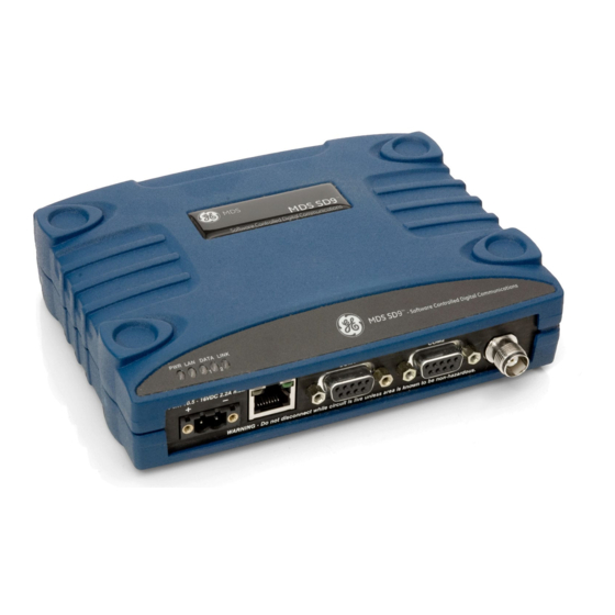
LED INDICATOR
PANEL
CONNECTOR (RJ-45)
DC INPUT
POWER
SERIAL DATA
CONNECTORS (DB-9)
COM1 used for radio management
Figure 1. MDS SD Data Transceiver
1.1
About This Guide
This guide covers SD transceivers operating in Packet Mode or
Transparent Mode. A more detailed Reference Manual is also
available (05-4846A01). SD manuals are available in printed or
electronic form. All manuals are available free of charge at
www.gemds.com.
1.1.1
x710 Mode—Different Manuals Required
The radio can be configured to emulate an MDS 4710 (400 MHz)
or 9710 (900 MHz) radio. (These radios are referred to as "x710"
here.) For x710 mode commands, consult these manuals:
• Start-Up Guide (05-4669A01)
• Reference Manual (05-4670A01)
2.0
INSTALLATION
There are three main requirements for installing the transceiver...
• Adequate and stable primary power
• An efficient and properly installed antenna system
• Correct interface connections between the transceiver and
the data device.
Figure 2 on Page 1
shows a typical installation of the radio.
NOTE: Retrofit Kits are available to ease installation at former
MDS x710 digital and analog sites. Consult the Refer-
ence Manual for details.
2.1
Installation Steps
In most cases, the steps given here are sufficient to install the
transceiver. Refer to the Reference Manual for additional details,
as required.
1. Mount the transceiver using the brackets supplied. Attach
the brackets to the bottom of the transceiver case (if not
already attached), using the four 6-32 x 1/4 inch (6 mm)
05-4847A01, Rev. B
(Figure
1) is a software-configu-
ETHERNET
ANTENNA
CONNECTOR (TNC)
Invisible
place
holder
Invisible
place
holder
MDS SD Series Quick Start Guide
Quick Start Guide (Firmware 3.x)
screws. Mounting bracket dimensions are shown in
If DIN Rail mounting brackets are to be used, consult the
Reference Manual.
NOTE: To prevent moisture from entering the radio, do not mount
the case with the cable connectors pointing up. Also,
dress all cables to prevent moisture from running along
the cables and into the radio.
CAUTION:Using screws longer than 1/4 inch (6 mm) to attach the
brackets to the radio may cause internal damage. Use
only the supplied screws.
ANTENNA SYSTEM
Master Stations typically use
omni-directional antenna
TRANSCEIVER
POWER SUPPLY
10.5–16 VDC @ 2.5A
Negative Ground Only
OR:
DATA TELEMETRY DEVICE
OR HOST COMPUTER
Figure 2. Typical Installation
7.25˝ (16.99 cm)
Figure 3. Mounting Bracket Dimensions
2. Install the antenna and feedline. The antenna used with the
radio must be designed to operate in the radio's frequency
band, and be mounted in a location providing a clear path to
the associated station(s). At Remote sites, aim directional
antennas toward the Master Station. Low loss coaxial feedline
should be used and it should be kept as short as possible.
3. Connect the data equipment. Connection may be made
using Ethernet signaling, Serial protocols (RS-232/RS-485),
or both.
MDS SD Series
Figure
3.
1

Related Manuals for GE MDS SD Series


Summary of Contents for GE MDS SD Series
-
Page 1: Installation Steps
3. Connect the data equipment. Connection may be made the brackets to the bottom of the transceiver case (if not using Ethernet signaling, Serial protocols (RS-232/RS-485), already attached), using the four 6-32 x 1/4 inch (6 mm) or both. 05-4847A01, Rev. B MDS SD Series Quick Start Guide... - Page 2 HyperTerminal (included with most Windows®-based PCs, except Vista) and set the following parameters: 8 bits, no parity, one stop bit (8N1), flow control disabled, VT100 Figure 8. Basic Settings Menu MDS SD Series Quick Start Guide 05-4847A01, Rev. B...
-
Page 3: Event Codes
Watch the RSSI indication for several seconds after making each adjustment so that the RSSI accurately reflects any change in the link signal strength. With RSSI, the less negative the number, the stronger the incoming signal. 05-4847A01, Rev. B MDS SD Series Quick Start Guide... -
Page 4: Menu System
PC Spacebar is used to make some menu selections. Event Log I/O Statistics Ethernet Statistics Telnet GE MDS, LLC 175 Science Parkway Rochester, NY 14620 MDS SD Series Quick Start Guide General Business: +1 585 242-9600 05-4847A01, Rev. B FAX: +1 585 242-9620 September 2009 Web: www.gemds.com...