Samsung OfficeServ 7400 General Description Manual
Hide thumbs
Also See for OfficeServ 7400:
- Technical manual (381 pages) ,
- General description manual (95 pages) ,
- Installation manual (87 pages)
Table of Contents
Quick Links
Table of Contents

Related Manuals for Samsung OfficeServ 7400


Summary of Contents for Samsung OfficeServ 7400
- Page 1 Enterprise IP Solutions OfficeServ 7400 General Description...
- Page 2 Disclaimer Samsung Business Communications is not responsible for errors or problems arising from customers not installing, programming or operating their Samsung systems as described in this manual. Copyright 2006 Samsung Business Communications All rights reserved.
- Page 3 Samsung Electronics Co., Ltd. 259 Gongdan-Dong, Gumi-City Kyungbuk, Korea, 730-030 (factory name, address) declare under our sole responsibility that the product Digital Keyphone System model "OfficeServ 7400" to which this declaration relates is in conformity with Low Voltage Directive 73/23/EEC EMC Directive 89/336/EEC:92/31/EEC...
-
Page 4: Intended Use
Intended Use This telephone system is intended to provide the user with voice communication between the system extensions and connection to the public switched telephone network by digital or analogue links. The telephone system may be provided with the ability to communicate with local computer networks to provide CTI functions and features. -
Page 5: Introduction
INTRODUCTION Purpose This guide provides comprehensive descriptions of the hardware configurations, specifica- tions and business functions of the Samsung Enterprise Solutions OfficeServ 7400 key telephone system. Guide Content and Organization This guide contains four chapters and a section on abbreviations used in the guide. -
Page 6: Conventions
Indicates additional information as a reference. Reference OfficeServ 7400 Installation Guide Describes the conditions necessary for installing the OfficeServ 7400 system, the installa- tion procedures, and how to operate and maintain the system correctly. OfficeServ 7400 Programming Guide Provides comprehensive instructions for programming your OfficeServ 7400 system using MMC programs. -
Page 7: Table Of Contents
OfficeServ 7400 General Description TABLE OF CONTENTS INTRODUCTION Purpose ..............................i Guide Content and Organization ......................i Conventions ............................ii Reference..............................ii CHAPTER 1. Overview of OfficeServ 7400 Introduction to System 1.1.1 Main Functions ........................1-1 1.1.2 System Architecture ......................1-3 1.2 Interfaces 1.2.1 Interfaces between Sub-modules .................. - Page 8 Loud Bell..........................2-46 2.6.4 Common Bell........................2-46 2.6.5 OfficeServ Manager (OSM)....................2-46 2.6.6 SMDR ..........................2-47 2.6.7 CTI ............................2-47 CHAPTER 3. OfficeServ 7400 Specifications 3.1 System Capacity 3.1.1 Trunk Line Capacity.......................3-2 3.1.2 Station (Subscriber) Line Capacity..................3-3 3.1.3 Number of Channels ......................3-3 3.2 Electrical Specifications 3.2.1...
- Page 9 3.4.1 Ring Cycles .........................3-15 3.4.2 Tones ...........................3-15 3.5 Available Terminals 3-16 3.6 Equipment Specification 3-17 CHAPTER 4. OfficeServ 7400 Functions 4.1 Call Functions 4.1.1 Dynamic IP Address Allocation ..................... 4-1 4.1.2 VoIP UMS Interface....................... 4-2 4.1.3 Router ALG Interface......................4-2 4.2 Data Server Functions...
- Page 10 Table of Contents List of Figures Figure 1.1 Configuration of OfficeServ 7400 Services ............1-3 Figure 1.2 Interfaces between VoIP Components ..............1-8 Figure 2.1 Configuration of OfficeServ 7400 Chassis .............2-3 Figure 2.1 Basic Chassis Configuration ..................2-3 Figure 2.2 Front Panel of MP40 Module .................2-7 Figure 2.3 Front Panel of LP40 Module ................2-10...
- Page 11 OfficeServ 7400 General Description List Of Tables Table 1.1 Interfaces between Sub-Modules ................1-6 Table 2.1 Rear Panel of OfficeServ 7400 Basic Chassis ............2-4 Table 2.2 Mountable Modules....................2-4 Table 2.3 Modules by Function....................2-5 Table 2.4 Specifications of MP40 Module................2-6 Table 2.5 Front Panel of MP40 Module ..................
- Page 12 Table 3.18 Electrical Characteristics of the VDSL Interface ..........3-11 Table 3.19 I/O Voltage of PSU ....................3-13 Table 3.20 System Ring Cycles ....................3-15 Table 3.21 System Tones Cycles ..................3-15 Table 3.22 OfficeServ 7400 Compatible Terminals..............3-16 viii © Samsung Business Communications...
-
Page 13: Chapter 1. Overview Of Officeserv 7400
1.1 Introduction to System OfficeServ 7400 is designed to meet the needs of mid- to large-sized offices and provides advanced functions including voice, data and internet functions. OfficeServ 7400 also pro- vides a data exchange function using the data network as well as the voice call function. - Page 14 CHAPTER 1. Overview of OfficeServ 7400 WAN and LAN Functions OfficeServ 7400 is equipped with WAN and LAN interface modules so that it can ex- change data with the external Internet and internal Intranet via 10/100 BASE-T or 1000 BASE-TX/SX/LX interfaces without additional data equipment.
-
Page 15: System Architecture
OfficeServ 7400 General Description 1.1.2 System Architecture OfficeServ 7400 is configured with a basic chassis and expansion chassis installed in the 19-inch rack, and the OfficeServ feature server installed on an external Linux server. The Main Control Processor (MP40) module is installed in the basic chassis and manages the overall operation of the system. - Page 16 CHAPTER 1. Overview of OfficeServ 7400 Voice Trunk Line Component The voice trunk line component is configured with digital trunk lines and analogue trunk lines. T1E1PRI (TEPRI)/TEPRI2 functions as an E1, T1 and Primary Rate Interface (PRI) digital trunk line module, sends/receives voice data through the trunk line and transmits the information at 64 kbps per channel.
- Page 17 AP and sends/receives voice to/from the phone system and wireless AP. The 4WLI module supports up to four APs (WBS24 Combo) and the OfficeServ 7400 system accommodates up to 16 x 4WLI modules and 640 subscribers.
-
Page 18: Interfaces
CHAPTER 1. Overview of OfficeServ 7400 1.2 Interfaces This section describes the interfaces between the sub-modules of OfficeServ 7400 and between the VoIP elements. 1.2.1 Interfaces between Sub-modules Table 1.1 Interfaces between Sub-Modules Categories Types Interfaces LIM/PLIM Inter- Physical Access IEEE 802.3 10 BASE-TX, IEEE 802.3u 100 BASE-TX... - Page 19 OfficeServ 7400 General Description Table 1.1 Interface between Sub-Modules (Continued) Categories Types Interfaces Interface between Physical Access DPRAM (Dual Port RAM) Call Server and Signal Process IPC (Inter-Processor Communication) Message Data Server Access Protocol Samsung Proprietary Message (GWIM, GSIM, GPLIM)
-
Page 20: Interfaces Between Voip Components
CHAPTER 1. Overview of OfficeServ 7400 1.2.2 Interfaces between VoIP Components OfficeServ 7400 provides various VoIP interfaces as follows: VoIP Networking H.323 VoIP Gateway SIP VoIP Gateway System SIP User Agent (UA) IP Telephone For signal processing, the interface standards between VoIP components are as follows:... -
Page 21: Programming
OfficeServ 7400 General Description 1.3 Programming Samsung’s Man Machine Communication (MMC) programs are used to set and change the data values for system operation. MMCs operate at three levels: technician (or system), administrator (or operator/customer), and subscriber (or station user). Access to an MMC may be controlled by a password depending on its action: a password is required for technician-level programming and administrator-level programming but not for subscriber-level programming. -
Page 22: Chapter 2. Officeserv 7400 Hardware
This chapter describes the hardware in detail, including chassis configurations and module functions and configurations. In addition, it describes terminals, wireless LAN equipment, and additional equipment available for the OfficeServ 7400. Hardware is installed as described in the OfficeServ 7400 Installation Guide provided with your system. 2.1 Hardware Features... - Page 23 CHAPTER 2. OfficeServ 7400 Hardware Maintenance The hardware is designed to be maintained with ease and safety. The 19-inch rack is designed to maintain sufficient strength. Installers and maintainers can connect/disconnect cables easily because the connection ports are placed on the front panel.
-
Page 24: Chassis Configuration
OfficeServ 7400 General Description 2.2 Chassis Configuration OfficeServ 7400 comprises a basic chassis and one or two expansion chassis installed in a 19-inch rack. A functional server operates externally. The Main Control Processor (MP40) module is installed in the basic chassis; it manages the overall operation of the OfficeServ 7400 and performs switching, signal processing and subscriber station management func- tions. -
Page 25: Configuration Of Slots
2.2.1 Configuration of Slots The basic chassis and expansion chassis each have 12 slots in which modules can be mounted. The modules mounted depend on the configuration of the OfficeServ 7400 (see Table 2.2). Table 2.2 Mountable Modules... -
Page 26: Modules By Function
This section describes the configuration and functions of the MP40 and LP40 control mod- ules. 2.3.1.1 MP40 (Main Control Module) MP40 is the main control module for all functions of the OfficeServ 7400 and is mounted in slot 3 of the basic chassis. The MP40: performs voice switching and signal processing;... -
Page 27: Table 2.4 Specifications Of Mp40 Module
CHAPTER 2. OfficeServ 7400 Hardware Main Functions The MP40 module offers the following functions: Various application operations via the LAN interface Convenient installation via Smart Media Database backup Port for Universal Asynchronous Receiver and Transmitter (UART) test External/Internal Music On Hold (MOH) and Loud/Common Bell functions... -
Page 28: Figure 2.2 Front Panel Of Mp40 Module
OfficeServ 7400 General Description Table 2.4 Specifications of MP40 Module (Continued) Categories Names Standards Time Switch Device ZL50018 Basic Switch 2048 x 2048 Channel Data Bus Width 16 bit Device EPSON_8563BN Time for Backup 24 Hours SmartMedia Capacity 32 MB... - Page 29 CHAPTER 2. OfficeServ 7400 Hardware Table 2.5 Front Panel of MP40 Module (Continued) Ports and LEDs Functions RUN LED Status of MP40 operation - Off: No power - On (Green): Booting - Blink (Green): Normal Operation (The blink cycle is 500 ms while running software)
-
Page 30: Optional Modules
OfficeServ 7400 General Description Optional Modules The optional modules available to mount on the LP40 module are the MFM, MIS, RCM2, SCM and CRM modules. Multi-Frequency Module (MFM): MFM contains ASIC chips for detecting DTMF sig- nals. It can detect DTFM signals from 12 channels simultaneously. MFM is installed in LOC1 or LOC2 of the LP40 (the location is indicated on the LP40 module). -
Page 31: Figure 2.3 Front Panel Of Lp40 Module
CHAPTER 2. OfficeServ 7400 Hardware Specifications The specifications of the LP40 are shown in Table 2.6. Table 2.6 Specifications of LP40 Module Category Name Standard Processor MPC852T System Clock 50 MHz Package 256P PBGA SDRAM Capacity 16 MB (For program and data storage) -
Page 32: Table 2.7 Front Panel Of Lp40 Module
OfficeServ 7400 General Description The components on the front panel have the following functions: Table 2.7 Front Panel of LP40 Module Port / LED Function Description LINK1~LINK3 Ports for connecting MP40 and LP40 MISC1~MISC2 Ports for connecting external music, paging, loud bell, common bell and door... -
Page 33: Voice Trunk Line Module
CHAPTER 2. OfficeServ 7400 Hardware 2.3.2 Voice Trunk Line Module This section describes the modules offering the voice service of trunk lines. 2.3.2.1 TEPRI The T1E1PRI (TEPRI) module provides the digital trunk line. A TEPRI module provides E1, T1, ISDN and PRI, and functions as the Q-SIG. This module transmits voice via the trunk line and a channel transmits the voice data at 64 Kbps. -
Page 34: Table 2.8 Front Panel Of Tepri Module
OfficeServ 7400 General Description The components on the front panel of the TEPRI module have the following functions: Table 2.8 Front Panel of TEPRI Module Port / LED Function Description T1/E1/PRI Ports for connecting T1/E1/PRI cables UART port (for testing) -
Page 35: Figure 2.5 Front Panel Of Tepri2 Module
CHAPTER 2. OfficeServ 7400 Hardware 2.3.2.2 TEPRI2 TEPRI2 provides the digital trunk line. A TEPRI2 module provides two ports for E1, T1, ISDN and PRI respectively, and functions as the Q-SIG. This module transmits voice via the trunk line and a channel transmits the voice data at 64 Kbps. -
Page 36: Table 2.9 Front Panel Of Tepri2 Module
OfficeServ 7400 General Description The components on the front panel of the TEPRI2 have the following functions: Table 2.9 Front Panel of TEPRI2 Module Port / LED Function Description Port 1 for connecting T1/E1/PRI cables Port 2 for connecting T1/E1/PRI cables... -
Page 37: Figure 2.6 Front Panel Of 4Bri Module
CHAPTER 2. OfficeServ 7400 Hardware Attenuates/compensates jitter as recommended in ITU-T I.431 and G703. Performs local/remote loopback for test. Specifications The 4BRI module has eight line ports. Front Panel The front panel of the 4BRI voice module is shown below: Figure 2.6 Front Panel of 4BRI Module... -
Page 38: Figure 2.7 Front Panel Of 8Trk Module
OfficeServ 7400 General Description Line monitoring for checking if the line is connected periodically to transmit the voice data. Function that operates as the relay paths for caller information. (When caller information is en- tered as 8TRK, it is available to make a path that verifies the call information in the RCM2 op- tion module by connecting the module to LP40.) -
Page 39: Voice Station Module
CHAPTER 2. OfficeServ 7400 Hardware 2.3.3 Voice Station Module This section describes the module that offers the station voice service. 2.3.3.1 8DLI The 8DLI (Digital Line Interface) module has eight ports for connecting digital phones to provide voice communication. Specifications... -
Page 40: Figure 2.9 Front Panel Of 8Combo Module
OfficeServ 7400 General Description 2.3.3.2 8COMBO The 8COMBO module has eight ports for analogue phones and eight ports for digital phones to provide voice communication. Main Functions The main functions of the 8COMBO voice station module are as follows: Generates ring at 20/25 Hz... -
Page 41: Figure 2.10 Front Panel Of 16Mwsli Module
CHAPTER 2. OfficeServ 7400 Hardware 2.3.3.3 16MWSLI The 16MWSLI module has 16 ports for analogue phones to provide voice communication. It also provides a message waiting function. Main Functions The main functions of the 16MWSLI module are as follows: Generates ring at 20 Hz... -
Page 42: Figure 2.11 Front Panel Of 16Dli2 Module
Figure 2.11 Front Panel of 16DLI2 Module The components on the front panel of the 16DLI2 have the following functions: Table 2.15 Front Panel of 16DLI2 Module Port / LED Function Description P1~P16 Station ports for Samsung digital phones 2-21 © Samsung Business Communications... -
Page 43: Data Server Modules
CHAPTER 2. OfficeServ 7400 Hardware 2.3.4 Data Server Modules This section describes the data modules for transmitting/receiving data to/from the Internet or Intranet. 2.3.4.1 LIM The LAN Interface Module (LIM) transmits/receives data on the Intranet. It provides the 10/100 BASE-T interface and functions as a hub for switching. -
Page 44: Figure 2.13 Front Panel Of Plim Module
PLIM can select the internal PSU (connecting shunt pins 1 and 2) or external rectifier (connecting shunt pins 2 and 3) using the shunt pins (J1, J2, J3). For details, see the Samsung OfficeServ 7400 Installation Guide. Specifications The PLIM data module provides 16 x 10/100 BASE-T ports. -
Page 45: Table 2.17 Front Panel Of Plim Module
CHAPTER 2. OfficeServ 7400 Hardware The components on the front panel of the PLIM module are as follows: Table 2.17 Front Panel of PLIM Module Port / LED Function Description P1~P16 Ports for connecting to Ethernet Left LED of each port... -
Page 46: Figure 2.14 Front Panel Of Gplim Module
OfficeServ 7400 General Description Front Panel The front panel of the GPLIM data module is shown below: LNK ACT LNK ACT GPLIM? Figure 2.14 Front Panel of GPLIM Module The components on the front panel of GPLIM function as follows: Table 2.18 Front Panel of GPLIM Module... -
Page 47: Figure 2.15 Front Panel Of Gsim Module
CHAPTER 2. OfficeServ 7400 Hardware 2.3.4.4 GSIM The Gigabit Switch Interface Module (GSIM) provides Gigabit LAN layer 2 and layer 3 in- terfaces to support the data network. Main Functions The main functions of the GSIM data module are as follows:... - Page 48 OfficeServ 7400 General Description 2.3.4.5 GWIM The Gigabit WAN Interface Module (GWIM) provides WAN interfaces to support the data network to the keyphone system. GWIM provides a leased line for data communication be- tween the keyphone system and the Internet, supports connection of an xDSL/cable modem interface, and performs functions for VPN, QoS and Firewall.
-
Page 49: Figure 2.16 Front Panel Of Gwim Module
CHAPTER 2. OfficeServ 7400 Hardware Front Panel The front panel of the GWIM data module is shown below: RUN V35 HSSI HSSI GWIM Figure 2.16 Front Panel of GWIM Module The components on the front panel of the GWIM module are as follows: Table 2.20 Front Panel of GWIM Module... -
Page 50: Figure 2.17 Front Panel Of 4Dsl Module
OfficeServ 7400 General Description 2.3.4.6 4DSL The 4DSL (Digital Subscriber Line) module uses VDSL technology to send/receive data to/from external IP devices on the Intranet. (Applied after V2.45.) Specifications Quadrature Amplitude Modulation (QAM) for four VDSL ports Transmission distance: 1.0 km Up/Down Links −... -
Page 51: Voice Application Module
CHAPTER 2. OfficeServ 7400 Hardware 2.3.5 Voice Application Module This section describes the interface module using Digital Adaptor for Subscriber Loop (DASL) to send/receive voice to/from the phone system and wireless base station. It con- verts voice to data and sends/receives the data. -
Page 52: Table 2.22 Front Panel Of Mgi Module
OfficeServ 7400 General Description The components on the front panel of the MGI module function as follows: Table 2.22 Front Panel of MGI Module Port / LED Function Description Ports for connecting Ethernet UART port (for testing) Button for resetting MGI module... -
Page 53: Figure 2.19 Front Panel Of Mgi64 Module
CHAPTER 2. OfficeServ 7400 Hardware 2.3.5.2 MGI64 The MGI64 module transmits and receives voice via the data network after converting it into data. The MGI64 is provided with up to 64 channels and decompresses voice using G.729, G.723, G.726 and G.711. The MGI64 provides the VoIP functions to serve as both client and server. - Page 54 OfficeServ 7400 General Description Table 2.23 Front Panel of MGI64 Module (Continued) Port / LED Function Description LAN TX LED Ethernet Data Transmission - Off: No data - On or Blink: Data are being transmitted LAN Rx LED Links and Ethernet Data Reception...
-
Page 55: Figure 2.20 Front Panel Of 4Wli Module
CHAPTER 2. OfficeServ 7400 Hardware Front Panel The front panel of the 4WLI module is shown below: SW1 SW2 SW3 4WLI Figure 2.20 Front Panel of 4WLI Module The components on the front panel of the 4WLI have the following functions: Table 2.24 Front Panel of 4WLI Module... -
Page 56: Svmi-20E
Voice ports can be added easily if necessary (modular design). Only one SVMi-20E can be installed in the OfficeServ 7400 system. Other voice mail systems cannot connect to SVMi-20E. When a voice message (.wav) or fax message (.tiff) is left, E-Mail Gateway delivers that message to the subscriber's e-mail inbox. -
Page 57: Table 2.25 Main Svmi-20E Module
CHAPTER 2. OfficeServ 7400 Hardware The components on the front panel of the main SVMi-20E module have the following functions: Table 2.25 Main SVMi-20E Module Category Function Description The LAN interface connector is used for data transmission and data- base backup and restoration. -
Page 58: Station Phones
OfficeServ 7400 General Description 2.4 Station Phones This section describes the types and features of analogue/digital station phones that can be connected to the OfficeServ 7400 system. 2.4.1 Analogue Phones Analogue phones are connected to ports of the 8COMBO/16MWSLI module. - Page 59 CHAPTER 2. OfficeServ 7400 Hardware 21-Button 2-Line LCD Keyset (DS-5021D) 48-character display (2x24) LCD with 3 associ- ated soft keys and scroll key 21 programmable keys Navigation keys for easy use of keyset functions Five fixed-function keys Built-in speakerphone Keyset Status Indicator...
- Page 60 OfficeServ 7400 General Description 38-Button 2-Line LCD Keyset (DS-5038S) 48-character display (2x24) LCD with 3 associated soft keys and scroll key 38 programmable keys Five fixed-function keys Built-in speakerphone Keyset Status Indicator Eight selectable ring tones Volume Up/Down keys for digital control...
-
Page 61: Ip Phones
CHAPTER 2. OfficeServ 7400 Hardware 2.4.3 IP Phones Internet (IP) phones use IP addresses to send/receive voice and data. They use existing data network lines so do not need normal phone lines, and can be connected to devices such as a switching hub. - Page 62 OfficeServ 7400 General Description 21-Button 2-Line LCD IP Keyset (ITP-5021D) 48-character display (2x24) LCD with 3 associated soft keys and scroll key Supports data and voice transfer using Internet Protocol 21 programmable keys Navigation keys for easy use of keyset func-...
- Page 63 CHAPTER 2. OfficeServ 7400 Hardware 14-Button 2-Line LCD IP Keyset (ITP-5114D) 48-character display (2x24) LCD with 3 associated soft keys and scroll key Supports data and voice transfer using Internet Protocol 14 programmable keys Navigation keys for easy use of keyset...
-
Page 64: Add-On Module (Aom)
OfficeServ 7400 General Description 7-Button 2-Line LCD Keyset (DS-5107S) 48-character display (2x24) LCD with 3 associated soft keys and scroll key Supports data and voice transfer using Internet Protocol Seven programmable keys Five fixed-function keys Built-in speakerphone Keyset Status Indicator... -
Page 65: Door Phone And Door Phone Interface Module (Dpim)
CHAPTER 2. OfficeServ 7400 Hardware KDB-Full Duplex (KDB-F) The standard speakerphone mode of operation for 2-line LCD keysets is ‘half duplex’. This means that you cannot transmit and receive speech at the same time. Adding a KDB-F to your keyset will convert the speakerphone into full duplex mode, enhancing its operation. -
Page 66: Wireless Lan Device
This section describes the wireless LAN Access Point (AP) and mobile stations that can be connected with the OfficeServ 7400 system. Two types of AP are available: the WBS24 (Combo), connected via the 4WLI card, and the WBS24 (Basic), connected via the MGI card. -
Page 67: Additional Devices
2.6.2 External Speakers The OfficeServ 7400 can be connected with external units such as amplifiers or speakers in addition to the phones’ internal speakers. The external units are connected via the MISC1 port of the MIS module, an optional module that can be mounted on the LP40 control module. -
Page 68: Smdr
The Station Message Detail Recording (SMDR) function manages the entire calling data, such as calls between station subscribers connected with the OfficeServ 7400, and local/long dis- tance/international calls. Connect the SMDR printer or PC with the OfficeServ 7400 to use the SMDR data provided by the system. -
Page 69: Table 3.1 Officeserv 7400 Capacity
3.1 System Capacity Up to 1344 lines can be installed and operated in the OfficeServ 7400 system, and the ratio of station to trunk lines can be adjusted depending on users’ needs. Table 3.1 below shows the maximum line capacity of the OfficeServ 7400. -
Page 70: Chapter 3. Officeserv 7400 Specifications
CRM: Up to 6 per system (MFM (20), R2 (16), or CID (16)) 3.1.1 Trunk Line Capacity The maximum trunk line capacity of the OfficeServ 7400 based on its configuration is shown in the table below: Table 3.2 Trunk Line Capacity... -
Page 71: Station (Subscriber) Line Capacity
OfficeServ 7400 General Description 3.1.2 Station (Subscriber) Line Capacity The maximum station line capacity for analogue phones, digital phones and IP phones in the OfficeServ 7400, based on its configuration, is shown in Table 3.3. Table 3.3 Station Line Capacity Maximum per Chassis... -
Page 72: Electrical Specifications
CHAPTER 3. OfficeServ 7400 Specifications 3.2 Electrical Specifications 3.2.1 Signal Specifications The signal processing protocol refers to the method of sending signals between the trunk lines, stations and system, and how status information is provided. 3.2.1.1 Trunk Line Signalling Type... -
Page 73: Table 3.6 Electrical Characteristics Of The E1 Trunk Line
OfficeServ 7400 General Description The signalling specifications and the signalling method of the T1 trunk line should com- ply with the ITU G.703 and G.704 standards. E1 Trunk Line The electrical characteristics of the E1 trunk line comply with the ITU G.703 and the G.704 standards. -
Page 74: Table 3.8 Electrical Characteristics Of The Pri Trunk Line
CHAPTER 3. OfficeServ 7400 Specifications The electrical characteristics of the ISDN (PRI) interface comply with the ITU I.431 and ETS 300 011 standards Table 3.8 Electrical Characteristics of the PRI Trunk Line Categories Specifications Transmission speed 2048 kbit/s ±50 ppm... - Page 75 OfficeServ 7400 General Description The electrical characteristics of the RS-232C (V.28) interface are shown in the table be- low: Table 3.11 Electrical Characteristics of the GWIM Interface (RS-232C Interface) Categories Specifications Maximum transmission speed 230 kbit/s Transmission code V.28 driver...
- Page 76 CHAPTER 3. OfficeServ 7400 Specifications 3.2.1.3. Signalling Type of the LAN The electrical characteristics of the 10 Base-T interface, which comply with the IEEE802.3 standards, are shown in the table below: Table 3.13 Electrical Characteristics of the LAN Interface (10 Base-T)
- Page 77 OfficeServ 7400 General Description The electrical characteristics of the 1000 BASE-TX interface, which comply with the IEEE802.3ab standards, are shown in the table below: Table 3.15 Electrical Characteristics of LAN Interface (1000 BASE-TX) Categories Specifications Transmission speed 1000 Mbps 8B1Q4...
- Page 78 CHAPTER 3. OfficeServ 7400 Specifications Table 3.17 1000 BASE-SX/LX Optical Fibre Mode Band Transmission Distance (m) Fibre Type (Short Wave/Long 1000BASE-SX 1000BASE-LX Wave MHz.Km) 62.5uM MMF 160/500 200/500 50uM MMF 400/400 500/500 Mode Band The mode band shown in the above table is a quality indicator of the multimode optical fibre related to the transmission speed.
- Page 79 OfficeServ 7400 General Description 3.2.1.4 Station Signalling Type Dial Pulse Signalling Type Ratio - 10 Pulses Per Second (PPS) Make/Break Ratio (M/B ratio) - 33% : 66% (can be adjusted in the software) The minimum signalling time between digits - 20 msec (can be adjusted in the software)
-
Page 80: Transmission Characteristics
CHAPTER 3. OfficeServ 7400 Specifications 3.2.2 Transmission Characteristics Attenuation Attenuation between subscribers: Less than 6 dB Attenuation between the subscriber and local trunk line: Less than 0.5 dB Characteristic resistance of the line: 600 Ω Weighted noise: Less than -65 dBm... -
Page 81: Power Specifications
3.3 Power Specifications 3.3.1 OfficeServ 7400 System Power OfficeServ 7400 operates by AC input power or battery power. The system chassis is sup- plied with backup power of -54 V, -5 V, +5 V, +3.3 V, +12 V, or -56 V. -
Page 82: External Rectifier
Button for Using External Battery External Rectifier Red Line Blue Line External Battery Connection Socket OfficeServ 7400 Figure 3.2 External Rectifier External Rectifier Installation Refer to the Samsung OfficeServ 7400 Installation Guide for external rectifier in- stallation instructions. 3-14 © Samsung Business Communications... -
Page 83: Rings And Tones
The ON/OFF cycle can be adjusted by changing the values in the system data- base 3.4.2 Tones The output voltage and the frequency of the ring signals in the OfficeServ 7400 are as follows: Output voltage: 75 V Frequency: 20 Hz The OfficeServ 7400 provides various tones to notify users of the status of functional op- erations, and generally provide feedback to users. -
Page 84: Available Terminals
CHAPTER 3. OfficeServ 7400 Specifications 3.5 Available Terminals The terminals available to the OfficeServ 7400 are shown in the table below: Table 3.22 OfficeServ 7400 Compatible Terminals Types Terminals 5000 Series digital phones DS-5007S, DS-5014S, DS-5014D, DS-5021D, DS-5038S, DS-5012L/LE 5000 Series IP phones... -
Page 85: Equipment Specification
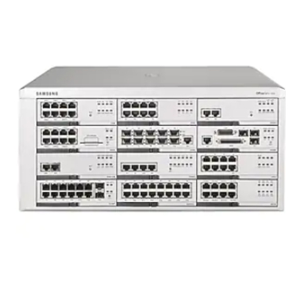
OfficeServ 7400 General Description 3.6 Equipment Specification The OfficeServ 7400 comprises one basic chassis to which one or two expansion chassis may be added as shown in the figure below: Expansion Chassis 2 Expansion Chassis 1 Basic Chassis Figure 3.3 OfficeServ 7400 Chassis Configuration Basic chassis only: 440(W) ×... -
Page 86: Chapter 4. Officeserv 7400 Functions
IP address. IP Phone Configuration The IP phones registered to the OfficeServ 7400 can be operated by receiving the dynami- cally allocated IP address from the data server, rather than by manually setting the IP ad- dress. -
Page 87: Voip Ums Interface
4.1.2 VoIP UMS Interface Auto Attendant/Mail Box Interface The OfficeServ 7400 uses SIP and RPT, the VoIP protocols, to provide the auto attendant and mailbox functions through the UMS and IP network operating in the feature server. To interface with the VoIP UMS, the MGI module should be installed in the system. -
Page 88: Data Server Functions
MAC address. The system automatically configures the VLAN for IP phones, signal processing gateway, media gateway, and UMS required for OfficeServ 7400 services, and performs the QoS process. OfficeServ 7400 provides 32 VLAN groups. - Page 89 QoS Function Supported OfficeServ 7400 provides the 802.1p Packet Priority and Level Classification Setup for supporting Quality of Service (QoS). The 802.1p Packet Priority is the expansion of the standard MAC header in the network packet. This expansion provides the packets with pri- ority: a packet of higher priority is treated preferentially and is processed ahead of a packet of lower priority.
-
Page 90: Routers
V.35 Interface (PPP, HDLC, Frame Relay) The OfficeServ 7400 accesses the Internet through the V.35 serial interface with a transfer speed of up to 2Mbps. In this case, the OfficeServ 7400 supports various environments us- ing functions such as PPP, HDLC, and Frame Relay Encapsulation. - Page 91 CHAPTER 4. OfficeServ 7400 Functions Multicast Routing Internet Group Management Protocol (IGMP) Internet Group Management Protocol (IGMP) protocol manages the multicast group op- erating at one Ethernet segment. It controls the segment so that a user can subscribe or secede as a member of the specific multicast group.
-
Page 92: Security
OfficeServ 7400 General Description 4.2.3 Security NAT/PT (In/Out/Exclusive/Redirect) The security function supports the conversion function between the private IP address and public IP address in the network where security is required. The Inbound, Outbound, Exclusive, and Redirect functions are supported. -
Page 93: Data Server Applications Functions
(such as the Internet) rather than the dedicated network. VPN Tunnel Mode VPN functions are processed by establishing a tunnel through the VPN gateways be- tween the OfficeServ 7400 data servers. Up to 100 VPN channels are available for one VPN. PPTP PPTP is a tunnelling protocol for using the IP-based network. - Page 94 OfficeServ 7400 General Description Outside ALG Interface This function enables an outside application to retrieve or control information such as NAT/PT conversion information, firewall blocking information, and VPN tunnel informa- tion processed in the data server. It allows control packets used for H.323, VoIP networking, and IP phones operating on the Call server, to be smoothly serviced without blocking.
-
Page 95: Ums Functions
CHAPTER 4. OfficeServ 7400 Functions 4.3 UMS Functions The OfficeServ 7400 provides the Unified Messaging System (UMS) which includes the auto answering, voice message, and integrated e-mail message management functions. VoIP UMS processes the call signal using the VoIP module, which has the SIP protocol for the interface to the voice switch, and transmits the media through the RTP protocol of the TCP/IP. -
Page 96: General Functions Related To Voice Mail
OfficeServ 7400 General Description Direct Connection to the Mailbox Allows access to the auto attendant and, using a prefix, directly connects the call to the mailbox of a specific subscriber rather than trying to connect the call to the subscriber’s station. - Page 97 CHAPTER 4. OfficeServ 7400 Functions Voice Message Pause/Play Continue/Next Play/Previous Play/Play Again The subscriber can pause the current message, play the next or previous messages, or play the current message again. New Message Auto Replay The subscriber logged in to the mailbox can optionally set whether to automatically replay new voice messages.
-
Page 98: Additional Functions Related To Voice Mail
OfficeServ 7400 General Description 4.3.3 Additional Functions Related to Voice Mail Answering Machine Emulation (AME) This function is similar to the auto answering machine. If a called party does not receive the call, it is forwarded to the AME. In this case, the called party can listen secretly to the forwarded call or reply to the call using the function key. -
Page 99: E-Mail General Functions
CHAPTER 4. OfficeServ 7400 Functions 4.3.4 E-mail General Functions Inbox Allows the subscriber to read stored mail. List View View the list of mail stored in Inbox. This functional button is displayed only when two frames are selected as ‘mail reading frame’ when setting the environment. - Page 100 OfficeServ 7400 General Description Text Write the text of the mail. Up to 2 Gbyte is available for a mail. Original Text Displays the text of the originally received mail. This is displayed only when replying to the original mail or transferring the original mail.
- Page 101 CHAPTER 4. OfficeServ 7400 Functions Mailbox Creation Specify the name of a newly created mailbox (up to 32 characters). Enter the name in the ‘Create New Mailbox’ field and click ‘Add’. Verify that the mes- sage notifying that the mailbox is correctly created is displayed and the name is dis- played in the ‘User Mailbox’...
- Page 102 OfficeServ 7400 General Description External Mail Importing The subscriber can import mail from other accounts into the OfficeServ 7400 mail account. For instance, mail from accounts in sites such as ‘Yahoo’ and ‘Naver’ can be read in the Of- ficeServ 7400 mailbox by registering the site(s) in the ‘External Mail Management’ item.
-
Page 103: Additional Functions Related To E-Mail
CHAPTER 4. OfficeServ 7400 Functions POP3 Receive Interface The system supports the Post Office Protocol 3 (POP3) as an E-mail receiving protocol. IMAP4 Receive Interface The system supports the Internet Message Access Protocol version 4 (IMAP4) as an E-mail receiving protocol. -
Page 104: Ums Management
Voice Text Upload/Download The user can upload audio text to the external computer from the system, or download it to the system from the external computer. It is used as the announcement for OfficeServ 7400. Alarm Information Management The user can specify the alarm level (Major, Minor) for alarms in the UMS and view the alarm information that has been generated over a specific period. -
Page 105: Web/System Management
CHAPTER 4. OfficeServ 7400 Functions 4.4 Web/System Management The OfficeServ 7400 provides the user interface for managing various system functional blocks on the web through the web browser. The system performs call server configuration management and information retrieval through OfficeServ Manager. The system also moni- tors the operational status of the functional blocks in the system. -
Page 106: System Management
The user can group events by arranging or searching events. Access Log Management This function displays the access log for the OfficeServ 7400. The user can group each ac- cess log by arranging and searching logs. -
Page 107: Abbreviations
OfficeServ 7400 General Description ABBREVIATIONS Auto Attendant Alternating Current Application Level Gateway Answering Machine Emulation Add-On Module Access Point Autonomous System ASIC Application Specific Integrated Circuit American Wire Gauge Bandwidth on Demand Basic Rate Interface Class Based Queuing Call Detail Record... - Page 108 HSSI High Speed Serial Interface Intrusion Detection System IGMP Internet Group Management Protocol IMAP4 Internet Message Access Protocol version 4 Internet Protocol Inter-Processor Communication IPSec Internet Protocol Security ISDN Integrated Services Digital Network International Telecommunication Union © Samsung Business Communications...
- Page 109 OfficeServ 7400 General Description Keyset Daughterboard L2TP Layer 2 Tunnelling Protocol Local Area Network Liquid Crystal Display Least Cost Routing Light Emitting Diode LAN Interface Module LP40 Local Control Processor Multi-Frequency Module Miscellaneous module Man Machine Communication MP40 Main Control Processor...
- Page 110 TAPI Telephony Application Programming Interface TEPRI T1 E1 Primary Rate Interface Type of Service Trunk Text-To-Speech User Agent UART Universal Asynchronous Receiver and Transmitter User Datagram Protocol Unified Messaging Service Universal Serial Bus Unshielded Twisted Pair © Samsung Business Communications...
- Page 111 OfficeServ 7400 General Description VDSL Very high bit rate Digital Subscriber Line VLAN Virtual Local Area Network Voice Mail System VoIP Voice over Internet Protocol Voice Processing Module Virtual Private Network Wide Area Network Wireless Base Station WAN Interface Module...
- Page 112 Samsung Business Communications Brookside Business Park, Greengate, Middleton, Manchester M24 1GS...