Table of Contents
Illustration: MD-M3
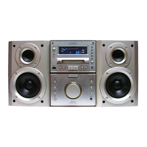
Illustration: MD-M1
IMPORTANT SERVICE NOTES (FOR U.S.A. ONLY) ........................................................................................................ 2
SPECIFICATIONS .............................................................................................................................................................. 3
NAMES OF PARTS ........................................................................................................................................................... 4
OPERATION MANUAL ....................................................................................................................................................... 7
QUICK GUIDE .................................................................................................................................................................... 9
DISASSEMBLY ................................................................................................................................................................ 11
REMOVING AND REINSTALLING THE MAIN PARTS ................................................................................................... 13
TEST MODE .................................................................................................................................................................... 15
ADJUSTMENT ................................................................................................................................................................. 17
EEPROM WRITING PROCEDURE .................................................................................................................................. 23
EXPLANATION OF MECHANISM ERROR ...................................................................................................................... 24
EXPLANATION OF ERROR DISPLAY ............................................................................................................................. 25
NOTES ON SCHEMATIC DIAGRAM .............................................................................................................................. 26
TYPE OF TRANSISTOR AND LED ................................................................................................................................. 26
BLOCK DIAGRAM ........................................................................................................................................................... 27
SCHEMATIC DIAGRAM / WIRING SIDE OF P.W.BOARD ............................................................................................. 32
WAVEFORMS OF CD CIRCUIT ...................................................................................................................................... 54
WAVEFORMS OF MD CIRCUIT ..................................................................................................................................... 55
TROUBLE SHOOTING (CD SECTION) .......................................................................................................................... 57
TROUBLE SHOOTING (MD SECTION) ........................................................................................................................... 61
TROUBLE SHOOTING (POWER SUPPLY SECTION) ................................................................................................... 65
FUNCTION TABLE OF IC ................................................................................................................................................ 66
REPLACEMENT PARTS LIST/EXPLODED VIEW/PACKING OF THE SET (FOR U.S.A.)
SERVICE MANUAL
CONTENTS
SHARP CORPORATION
- 1 -
MD-M3 MD micro System consisting of
MD-M3(main unit) and CP-M3(speaker
system).
MD-M1 MD micro System consisting of
MD-M1(main unit) and CP-M1(speaker
system).
• In the interests of user-safety the set should be restored to its original
condition and only parts identical to those specified should be used.
This document has been published to be used
for after sales service only.
The contents are subject to change without notice.
MD-M3/M1
No.S6940MDM3M1//
MD-M3
MD-M1
Page
Table of Contents
Troubleshooting

Related Manuals for Sharp MD-M3

Summary of Contents for Sharp MD-M3
-
Page 1: Table Of Contents
MD-M3/M1 SERVICE MANUAL No.S6940MDM3M1// MD-M3 MD-M3 MD micro System consisting of MD-M3(main unit) and CP-M3(speaker system). Illustration: MD-M3 MD-M1 MD-M1 MD micro System consisting of MD-M1(main unit) and CP-M1(speaker system). • In the interests of user-safety the set should be restored to its original condition and only parts identical to those specified should be used. -
Page 2: Important Service Notes (For U.s.a.only)
MD-M3/M1 FOR A COMPLETE DESCRIPTION OF THE OPERATION OF THIS UNIT, PLEASE REFER TO THE OPERATION MANUAL. IMPORTANT SERVICE NOTES (For U.S.A.Only) BEFORE RETURNING THE AUDIO PRODUCT (Fire & Shock Hazard) Before returning the audio product to the user, perform the following safety checks. -
Page 3: Specifications
Error correction: ACIRC (Advanced Cross In- terleave Reed-Solomon CP-M3/M1 Code) Speaker section Quantization: 20-bit linear (A/D converter) Type (MD-M3): 2-way speaker system Coding: ATRAC (Adaptive TRansform 4-3/4" (12cm) woofer, Acoustic Coding) 3/4" (2cm) tweeter Sampling Type (MD-M1): Full range speaker system frequency: 44.1 kHz... -
Page 4: Names Of Parts
12. (CD/MD) Track Up/Cue Button (TUNER) Preset Up Button 13. (CD/MD) Track Down/Review Button (TUNER) Preset Down Button 14. CD MD Normal Speed Edit Button (MD-M3 ONLY) 14. CD MD Edit Button (MD-M1 ONLY) 15. CD MD High Speed Edit Button (MD-M3 ONLY) 16. - Page 5 MD-M3/M1 Display window 1. Level Meters 2. Character Information Display SURROUND 3. Surround Indicator X-BASS OVER PLAY 4. Extra Bass Indicator DISC TOC TRACK MEMORY RANDOM 5. FM Stereo Indicator TOTAL MHz SLEEP REMAIN 6. FM Stereo Mode Indicator 7. (CD/MD) Disc Indicator 8.
- Page 6 MD-M3/M1 Remote control 1. Remote Control Transmitter LED 2. Surround Button 3. Clock Button 4. Timer Button 5. Name/TOC Edit Button 6. Sleep Button 7. (TUNER) Preset Up/Down Buttons 8. Extra Bass Button 9. Preset Equalizer Button 10. (MD) Display Button 11.
-
Page 7: Operation Manual
MD-M3/M1 OPERATION MANUAL – 7 –... - Page 8 MD-M3/M1 – 8 –...
-
Page 9: Quick Guide
MD-M3/M1 MD MICRO SYSTEM Listening to a CD / Audición de discos CD Quick Guide/Guía rápida MD-M3 Label side up POWER Con el lado de la Check the supplied accessories / Compruebe los accesorios suministrados etiqueta hacia arriba CD EJECT... - Page 10 MD-M3/M1 MD MICRO SYSTEM Quick Guide/Guía rápida MD-M1 Listening to a CD / Audición de discos CD Check the supplied accessories / Compruebe los accesorios suministrados Label side up POWER Con el lado de la etiqueta hacia arriba CD EJECT...
-
Page 11: Disassembly
11-2 Front Panel (Note 2) 2. Lead Wire ..(D2) x1 Main 3. Screw ....(D3) x6 4. Socket(MD-M3) ..(D4) x3 (D3)x1 4. Socket(MD-M1) ..(D4) x2 (D4)x1 ø3x10mm 5. Flat Cable ..(D5) x4 Power/Tuner PWB 1. Screw ....(E1) x4 11-3 2. - Page 12 MD-M3/M1 (F2)x1 ø3x10mm Front Panel (F1)x2 Front Panel ø3x10mm MD Unit (K1)x1 (F2)x4 ø3x12 mm MD Holder (K3)x2 ø2.6x10mm (G1)x4 Jack PWB (K2)x1 ø4x8mm Washer (F1)x2 ø3x10mm Display PWB (J1)x1 ø2.6x10mm (K3)x3 (H1)x2 ø2.6x10mm ø3x10mm Power PWB Figure 12-2 Figure 12-1 (L1)x3 ø2.6x10mm...
-
Page 13: Removing And Reinstalling The Main Parts
MD-M3/M1 REMOVING AND REINSTALLING THE MAIN PARTS MD MECHANISM SECTION (A1)x1 For details about the procedure to remove the MD mechanism ø1.7x5mm from the main unit, refer to the Disassembly Procedure, Steps 1-6 in the main unit and also the MD section. - Page 14 MD-M3/M1 (D1)x2 (D1)x2 How to remove the sled motor/loading motor ø1.7x2mm ø1.7x2mm (See Fig. 14-1) 1. Remove the screws (D1) x 4 pcs., and remove the sled motor/loading motor. Caution: Be careful so that the gear is not damaged. (The damaged gear emits noise during searching.)
-
Page 15: Test Mode
MD-M3/M1 CD MECHANISM SECTION CD Cover For details about the procedure to remove the CD mechanism from the main unit, refer to Disassembly Procedure, Steps 1 ( A2 ) x2 ,11 in the main unit and also the CD section. (p.11,12). -
Page 16: Tuner Section
MD-M3/M1 MD SECTION Test mode setting method 1. Holding down the MD FUNCTION button and FF( )button, press POWER button switch. (State A is changed to state B .) 2. Insert the playback disc 1 (high reflection disc) or recording disc 2 (low reflection disc).(State C is set.) Thus, the test mode state is set. -
Page 17: Adjustment
MD-M3/M1 ADJUSTMENT TUNER SECTION • FM mute level adjustment fL: Low-range frequency fH: High-range frequency FM signal oscillator Frequency 1 kHz, 40 kHz • AM adjustment and confirmation Frequency Adjusting Adjusting Adjusting object AM signal oscillator Frequency 400 Hz, 30%, AM modulation... - Page 18 MD-M3/M1 MD SECTION When the combination of mechanism/pickup and PWB was changed , set the TEST mode to perform the AUTO preliminary adjustment and AUTO adjustment, write the adjustment data in EEPROM. When EEPROM was replaced, set the TEST mode, write the EEPROM set data (p23,p24) and then perform the preliminary adjustment and AUTO adjustment, write adjustment data in EEPROM.
- Page 19 MD-M3/M1 • Test Mode 1. EJECT mode • TEMP setting (of EEPROM setting) • CONTROL setting (of EEPROM setting) • Setting of laser power (record/playback power) 2. AUTO pre-adjustment mode • Automatic pre-adjustment is performed. 3. AUTO adjustment mode • Automatic adjustment is performed. (After adjustment the grating adjustment mode is set.) •...
- Page 20 MD-M3/M1 1. EJECT mode Setting Method Step No. Remarks Display * Step 1 Test mode EJECT state [ _ _ E J E C T _ _ _ ] Step 2 Press once the DISPLAY button. Max. power output state...
- Page 21 MD-M3/M1 4. EEPROM setting mode Shown in page 23,24. 5. TEST-PLAY mode (For confirmation of the playback ability at the named address.) Step No. Setting Method Remarks Display * Step 1 Test mode STOP state The AUTO preliminary adjustment should have been completed.
- Page 22 MD-M3/M1 Lead-in switch position measurement mode Loosen the Insert High reflection test disk (TGYS1) two screws (A). Note: Adjust the lead-in switch position to FF85 to FFDF. 1. Loosen the screw (A) x 2 pcs. which fix the mechanism switch PWB.
-
Page 23: Eeprom Writing Procedure
MD-M3/M1 EEPROM WRITING PROCEDURE EEPROM DATA LIST (Version : 01) EEPROM (IC1402) writing procedure Focus setting 1. Method for setting the reference temperature value Item indication Setting (This setting should be performed quickly at a room temperature, between 21 C and 29 C when the PWB is not hot.) -
Page 24: Explanation Of Mechanism Error
MD-M3/M1 Slide setting Control setting Item indication Setting Item indication Setting S L G C O N T R L 1 S L 2 C O N T R L 2 S L D L I M S P K L E V m... -
Page 25: Explanation Of Error Display
MD-M3/M1 EXPLANATION OF ERROR DISPLAY Error display Corrective action Errors Can't REC • Defect occurred successively 10 times during REC-PLAY. • Check that the disc is free from flaw, dust • As a result of occurrence of defect during REC-PLAY the and fingerprint. -
Page 26: Notes On Schematic Diagram
Lead In SWD19 SWD20 SW1954 Play SW1955 SWD21 PLAY SW1956 Loading SWD22 STOP SWD01 POWER SWD23 HIGH (MD-M3 ONLY) SWD02 DISPLAY SWD24 NORMAL (MD-M3 ONLY) SWD24 CD MD EDIT (MD-M1 ONLY) SWD08 MD EJECT SWD10 SURROUND SWD25 MEMORY SWD11 EQUALIZER... -
Page 27: Block Diagram
MD-M3/M1 3.2V IC1300 XL1201 6.5/4.75~5.25V TC74ACT02F 33.8688MHz HEAD DRIVER RECORDING EXT. HEAD LRSY IC1201 LR376484 DATA ATRAC ENCODER/DECODER CN1502 MD-M3 ONLY M901 SPINDLE MOTOR M902 PICKUP UNIT 28P FFC SLED MOTOR DIGOUT D.GND DIGIN BACKUP FOCUS BACKUP LIGHT PDOWN TRACKING... - Page 28 MD-M3/M1 T302 COIL SO301 ANTENNA T306 COIL 75 OHMS –B2 FE301 IF OUT FM FRONT END SWITCHING RESET +12V IC901 Q904 Q360 XC61CN40 RESET +5V(D) SY-STOP FM/AM VOLTAGE REGULATOR Q371 FM/AM IC302 LC72131 TUN MUTE TUNER PLL COTROLLER MO/ST STEREO 21 17 4.5MHz...
- Page 29 MD-M3/M1 T991 POWER TRANSFORMER (MAIN) D951 VOLTAGE F995 REGULATOR 4A/125V +12V(D) Q801 F996 3.15A/125V VOLTAGE D952 REGULATOR +12V(A) Q802 Q803 VOLTAGE REGULATOR F997 VOLTAGE REGULATOR 3.15A/125V 12V(A) –30V –B2 Q808 Q951 –B1 VOLTAGE D953,D955 REGULATOR CD+7V Q809 TO CD Q810...
- Page 30 LOADSW MDAVCC AAGND ADGND LOUT AAGND ROUT LRSY DATACK CDGND1 VOLTAGE REGULATOR DATA CD+7V +B12 CNP13 +B12 MD-M3 ONLY VOLTAGE REGULATOR +B11 +3.3V +B10 +B10 VOLTAGE REGULATOR CD LID SW LID-SW +B11 PUIN PICKUP-IN SW PICKUP UNIT +B10 +3.3V 14 15...
- Page 31 10 11 12 13 14 15 16 17 18 19 20 21 22 23 24 25 26 27 28 29 30 QD04 –30V –B1 RXD01 REMOTE REMOCON SENSOR KEY1 KEY MATRIX +5V(D) SWD01-SWD08 SWD10-SWD16 +5V(D) KEY2 SWD19-SWD26 (SWD23 MD-M3 ONLY) BACK UP KEY3 Figure 31 BLOCK DIAGRAM (5/5) – 31 –...
-
Page 32: Schematic Diagram / Wiring Side Of P.w.board
AMP HPSW AMP TEMP AMP LEVEL RD59 100K CD SO( V LOAD CD SI( CNP12 CD RES MAIN PWB MDDATA MD-M3:P39 12-B SERCH MD-M1:P40 12-B (OPEN) MD-ST MD RES DSCK KDATA MD DSTB LOADSW AMP FAN SY MUTE AMP MUTE... - Page 33 RF18 RF22 RF19 RF20 RF21 RF23 1.2K 5.6K 1.8K 2.2K 3.9K SWD19 SWD20 SWD21 SWD22 SWD23 SWD24 SWD25 SWD26 PLAY/ HIGH STOP NORMAL MEMORY REVIEW PAUSE MD-M3 ONLY MD EDIT DISPLAY PWB-B1 Figure 33 SCHEMATIC DIAGRAM (2/14) – 33 –...
- Page 34 MD-M3/M1 MAIN PWB MAIN PWB CNP11 CNP12 MD-M3:P42 3-B MD-M3:P42 4-B MD-M1:P41 3-B MD-M1:P41 4-B FWD03 FWD02 DISPLAY PWB-B1 CD07 CNPD03 CNPD02 CD06 RD07 RD29 CD20 RD26 RD30 RD31 RD32 RD14 RD25 CD11 XD01 RD37 RD13 RD38 RD11 RD40 CD12...
- Page 35 MD SIGNAL RECORD SIGNAL MAIN PWB-A(1/3) CFWP12 6 7 8 9 10 11 12 13 TO CD SECTION MD-M3:P39 12-G FWP12 MD-M1:P40 12-G CFWR12 TO POWER/TUNER PWB P46 1-G • NOTES ON SCHEMATIC DIAGRAM can be found on page 26.
- Page 36 R807 C807 ZD802 C810 47/25 DZ13C 0.047 GND(A) ZD804 C812 R813 DZ13A 47/25 –13.15V C814 TO CD SECTION 10/35 MD-M3:P39 8~12-H R816 R852 MD-M1:P40 8~12-H (Fusible 1/4W) –B –12V(A) –12V(A) –12.59V –19.79V Q808 2SB1375 Q809 7.01V 2SD2012 +6V(CD) 18.25V +16V...
- Page 37 MD-M3/M1 MAIN PWB-A(2/3) FM SIGNAL RX58 ZDX52 CX53 FWX51 DZ6.2B 47/25 12.30V(10.96V) QX51 12.30V HSC1815 GR RX57 (7.89V) MOX51 3.9K RX56 FAN MOTOR 11.78V +12V(D) 4.7K QX52 CX51 RX53 RX59 KTA1270 Y 10/35 DGND RX60 DX56 DS1SS133 AMP FAN 12.30V(0.51V) QX53 (4.02V)
- Page 38 MD-M3/M1 CD LID 47/10 CNS2 0.047 0.01 1.5M 2.2/50 100/10 100/10 LA9235M DS1SS133 C16 6P 0.047 SERVO AMP. FIN1 1.64V 3.27V ODRV FIN2 1.64V 1.65V RFSW 100P TIN1 1.66V 1.65V RF– 5.05V 0.0027 3.99V TIN2 0.85V 1/66V KTC3199 GR 3.37V 10/35 0.01...
- Page 39 MD-M3/M1 MD-M3 FWD03 +5V(D) PROGRAM 0.001 PUIN (CLK) PU-IN LID SW(DATA) CD_CHACK RESET VDD5V GND(D) DGND CNP11 FWD02 –31(VP) POWER ON LC78640E AMP HPSW SERVO SIGNAL AMP TEMP CONTROL AMP LEVEL 0.047 80 79 78 77 76 75 74 73 72 71 70 69 68 67 66 65...
- Page 40 MD-M3/M1 MD-M1 FWD03 +5V(D) PROGRAM 0.001 PUIN (CLK) PU-IN CD_CHACK LID SW(DATA) RESET VDD5V GND(D) DGND CNP11 FWD02 –31(VP) POWER ON LC78640E AMP HPSW SERVO SIGNAL AMP TEMP CONTROL AMP LEVEL 80 79 78 77 76 75 74 73 72 71 70 69 68 67 66 65...
- Page 41 MD-M3/M1 MD-M1 DISPLAY PWB CNPD03 DISPLAY PWB CNPD02 CD MOTOR PWB CNP3 P34 2-B P34 4-B P49 11-B FWD03 FWD02 CD LID CNP12 CNP11 CNS15 B C E RP02 CNP14 RP01 DIG OUT CNW2002 3 2 1 1 2 3...
- Page 42 MD-M3/M1 MD-M3 DISPLAY PWB CNPD03 DISPLAY PWB CNPD02 CD MOTOR PWB CNP3 P34 2-B P34 4-B P49 11-B FWD03 FWD02 CD LID CNP12 CNP11 P53 7-H B C E MD MAIN PWB RP02 CNS13 CNP14 RP01 CNP13 DIG OUT CNS15...
- Page 43 MD-M3/M1 CD PICKUP UNIT(307) P49 7,8-B CNSX51 FAN MOTOR MOX51 Q813 3 2 1 ZD807 C810 Q951 ZD803 E C B C816 R819 Q810 R817 ZD61 R955 C817 R851 D801 C808 CNS991 C807 C809 R807 C802 TMX11 ZD802 R952 CNPX51...
- Page 44 MD-M3/M1 VD301-1 R319 T302 KV1236Z23F 100K R358 C330 C332 C343 8.2K 0.022 L353 AM ANT. (UJ) VR351 FM MUTE 10K(B) LEVEL C302 AUTO-STOP 0.001 CHASSIS GND C301 0.001 24 23 BI301 D301 VD301-2 R324 IC303 DS1SS133 MAIN RADIATOR T306 KV1236Z23F...
- Page 45 MD-M3/M1 R363 R364 2.2K 2.2K 4.5V C371 R361 Q351 1/50 2.2K KRC104 M R362 C372 2.2K 1/50 IC303 LA1832S FM IF DET./FM MPX./AM IF C358 1/50 R352 R353 C357 R355 2.2/50 3.3K CF352 AM IF R354 R370 4.7K CF351 FM IF...
- Page 46 MD-M3/M1 SWR11 DEMO SW FM SIGNAL VRR11 AUX INPUT LEVEL RR13 RR15 2.2K RR14 RR16 2.2K JR11 RR11 TP910 L-CH CR11 330P INPUT +12V(D) CR12 12.21V 330P R-CH +5V(D) 4.95V RR12 +5V BACK UP 4.87V DR12 +5V(D) 4.95V DS1SS133 P44 1-B...
- Page 47 MD-M3/M1 POWER/TUNER PWB-C1(2/2) IC902 D902 T990 1N4004S POWER TRANSFORMER (SUB) AN78L05 CONSTANT D906 DS1SS133 VOLTAGE REGULATOR D991-D994 D903 1N4004S C993 DS1SS133 D991 D994 0.047 D901 D904 (ML) 1N4004S DS1SS133 11.46V 5.64V 12.10V R907 4.7K D992 D993 0.59V IC901 4.95V C901...
- Page 48 MD-M3/M1 Bi301 POWER/TUNER PWB-C1 CD PICKU MAIN RADIATOR CHASSIS GND CHASSIS C301 D352 R372 Q371 R371 R374 R373 R360 C302 D351 2 3 4 5 6 7 8 9 10 11 SO301 Bi301 ANTENNA C387 IC302 C382 C386 R376 R384...
- Page 49 MD-M3/M1 CD PICKUP UNIT CD MOTOR PWB-F COLOR TABLE BROWN R D ( R ) SPINDLE MOTOR ORANGE P43 6-A MAIN PWB YELLOW CNS3 GREEN P43 8-A MAIN PWB BLUE CNS2 1 2 3 4 5 6 7 VIOLET PICKUP IN...
- Page 50 MD-M3/M1 MD MAIN PWB-D TP1124 TP1131 C1105 TP1125 TP1202 C1104 0.0033 C1110 0.033 0.0047 C1111 0.47 SYRS R1106 TP1201 0.7V 1.6V 1.48V TP1132 EFMMON 3.2V ADIPI AVCC 0.7V 1.6V EFMO-I C1201 TP1133 1.6V EFMI & C1112 ADIPO AGND 330P 0.7V...
- Page 51 1 2 3 4 5 6 7 8 9 10 11 12 13 14 R1429 1 2 3 4 89 88 87 86 85 84 83 82 81 C1708 0.01 L3CLK MD-M3 ONLY XRST C1705 L3MODE DIGCD DIGEX C1706 R1709...
- Page 52 IC1801 R1415 R1413 C1715 R1402 C1411 R1705 C1409 R1422 R1709 R1420 R1419 R1710 R1421 R1706 R1425 IC1402 R1423 C1410 MD-M3 ONLY R1208 C1204 L1201 C1206 R1200 MD-M1 ONLY C1207 R1201 R1202 R1223 R1102 R1203 R1210 R1101 C1202 L1200 R1100 C1616...
- Page 53 TP1104 TP1107 TP1121 C1102 TP1115 TP1102 TP1116 TP1604 TP1105 TP1123 TP1111 TP1110 TP1106 TP1137 CW1901 SW1953 LEAD IN R1904 MD-M3 ONLY SW1954 PLAY R1903 SW1955 RECORD CNS13 R1902 SW1952 SW1956 LOADING DISC MEDIA R1901 CNP13 WRITE PRO M902 M901 M903...
-
Page 54: Waveforms Of Cd Circuit
Stopped 1999/04/05 20:50:17 CH1=2V CH2=2V CH3=2V 5us/div DC 10:1 DC 10:1 DC 10:1 (5us/div) NORM:100kS/s CNP13 1 (For MD-M3) IC2 57 (For MD-M1) LRSY CNP13 2 IC1 27 (For MD-M3) IC2 58 DATACK (For MD-M1) CNP13 4 (For MD-M3) DATA... -
Page 55: Waveforms Of Md Circuit
MD-M3/M1 WAVEFORMS OF MD CIRCUIT PLAY STATE PIT PLAY Stopped Stopped NORM: 100M S/s NORM: 1M S/s 1997 / 08 / 04 09:30:15 1997 / 08 / 04 13:35:24 CH1 500mV 500ns/div 200mV 1ms/div AC 10:1 DC 10:1 DC 10:1... - Page 56 MD-M3/M1 PLAY Stopped Stopped NORM: 1k S/s 1997 / 08 / 04 14:19:52 NORM: 100M S/s 1997 / 08 / 04 11:23:12 1s/div 2us/div DC 10:1 DC 10:1 DC 10:1 DC 10:1 DC 10:1 DC 10:1 DC 10:1 Filter Filter...
-
Page 57: Trouble Shooting (Cd Section)
MD-M3/M1 TROUBLE SHOOTING CD SECTION When the CD does not function When the CD section does not operate when the objective lens of the optical pickup is dirty, this section may not operate. Clean the objective lens, and check the playback operation. When this section does not operate even after the above step is taken, check the following items. - Page 58 MD-M3/M1 (1) Focus-HF system check Stopped CH1=500mV CH3=500mV 500ms/div Although a CD is inserted and the cover is closed, "NO DC 10:1 DC 10:1 (500ms/div) NORM:20kS/s DISC" is displayed. Press the LID switch (SW1) without inserting a disc, and try starting the playback operation.
- Page 59 MD-M3/M1 (2) Tracking system check Check the TE waveform at pin 18 on IC1. The tracking servo is not activated. If the waveform shown in Figure 59-1 appears and soon after Check the peripheral circuits at pins 18 and 19 on IC1, pin 23 on NO DISC appears.
- Page 60 MD-M3/M1 (4) PLL system check Stopped 1999/04/05 17:33:17 CH1=500mV CH3=1V CH4=1V 500ms/div DC 10:1 DC 10:1 DC 10:1 (500ms/div) NORM:20kS/s PDO1 When a disc is loaded, start play operation. The HF waveform is normal, but the TOC data cannot be PDO2 read.
-
Page 61: Trouble Shooting (Md Section)
MD-M3/M1 MD SECTION When MD fails to operate If the objective lens of optical pickup is contaminated, MD may fail to operate. At first, clean the objective lens to check playback operation. If MD fails persistently to operate, perform checks as follows. - Page 62 MD-M3/M1 • Disc loading is not normal. Is disc loaded when it is inserted? Check CN1601 and SW1956. Is the pin 4 of CN1601 set to L state? Is change observed on the pin 23 or 24 of IC1601? Check IC1401.
- Page 63 MD-M3/M1 • Normal playback When it has been confirmed that EEPROM value is normal in the TEST mode Is initialization performed normally when high reflection disc is Does the playback time display advance? played back? Check IC1201 Does disc rotate normally?
- Page 64 MD-M3/M1 • Record and playback operation Insert the low reflection disc, and after verifying the audio output in the normal mode playback set the record/playback TEST mode Recording from start address cannot be performed. Check whether the disc is record-prohibited.
-
Page 65: Trouble Shooting (Power Supply Section)
MD-M3/M1 • Disc motor fails to run Does waveform appear on the pins 24 and 25 of IC1201 in the Check soldering joint and parts of pins 24 and 25 of IC1201, and peripheral circuit. TEST mode focus gain coarse adjustment step? -
Page 66: Function Table Of Ic
MD-M3/M1 FUNCTION TABLE OF IC IC1 VHiLA9235M/-1:Servo Amp. (LA9235M) ODRV FIN1 LA9235M RFSW FIN2 AGCON 28 RF- FIN3 FIN4 26 N/C 25 PH 24 BH REF1 ODRV 23 N/C PH/BH 22 RFEV VREF 21 FE- 20 FE LDOF 19 TE-... - Page 67 MD-M3/D1 IC2 VHiLC78640E-1:Servo/Signal Control (LC78640E) (2/3) Terminal Name Input/Output Setting in Reset Function Pin No. PDO1 Output – For PULL Phase-comparison output terminal for built-in VOC control. PDO2 Output – Phase-comparison output terminal for built-in VOC control. Rough servo : OFF, phase servo : ON.
- Page 68 MD-M3/M1 IC2 VHiLC78640E-1:Servo/Signal Control (LC78640E) (3/3) Terminal Name Input/Output Setting in Reset Function Pin No. LVDD – – L channel Power terminal for L channel. LCHO Output 1/2VDD D/A converter L channel output terminal. LVSS – – Ground terminal for L channel. Surely connected to 0V.
- Page 69 MD-M3/D1 IC3 VHiLA6548//-1: Focus/Tracking/Spin/Sled Driver (LA6548) Function Pin No. Terminal Name Power supply. (pin24 and short) MUTE ON/OFF for all CH output. VIN1 Channel 1 input terminal. Channel 1 input terminal. (gain control) VO1+ Channel 1 output terminal. (non-inverted) VO1–...
- Page 70 MD-M3/M1 ICD01 RH-iX0288AWZZ: System Microcomputer/FL Driver (iX0288AW) (1/2) Port Name Input/Output Function Terminal Name Pin No. CD_CE Output Serial control chip enable for CD DSP. CD_INT Input Serial control interruption for CD DSP. CD_WRQ Input Serial control write request for CD DSP.
- Page 71 MD-M3/D1 ICD01 RH-iX0288AWZZ: System Microcomputer/FL Driver (iX0288AW) (2/2) Port Name Input/Output Function Pin No. Terminal Name – – Power for fluorescent drive. –30V Output Fluorescent segment drive. Output Fluorescent segment drive. Output Fluorescent segment drive. Output Fluorescent segment drive. Output Fluorescent segment drive.
- Page 72 MD-M3/M1 ICP11 VHiM62439SP-1: Audio Processor (M62439SP) Function Terminal Name Pin No. REC OUT Channel 1 REC OUT terminal. Useable for spare input terminal. IN A1 IN B1 Channel 1 input terminal. IN C1 IN D1 TONEH1 Channel 1 treble frequency control terminal.
- Page 73 MD-M3/D1 ICP12 VHiLA2610//-1: Surround (LA2610) LEVEL ANALOG ON/OFF SURROUND BASS LB-ADJ LEVEL-ADJ 4.7u 0.01u 0.01u 4.7u 0.1u 18K GND=OFF OPEN=ON L-IN R-IN R-OUT L-OUT 4.5~12V Figure 73-1 BLOCK DIAGRAM OF IC FLD01 VVKBJ695GNK-1: FL Display SURROUND OVER X-BASS PLAY DISC TOC...
- Page 74 MD-M3/M1 – MEMO – – 74 –...
- Page 75 “HOW TO ORDER REPLACEMENT PARTS” To have your order filled promptly and correctly, please furnish the For U.S.A. only following information. Contact your nearest SHARP Parts Distributor to order. 1. MODEL NUMBER 2. REF. No. 3. PART NO. 4. DESCRIPTION For location of SHARP Parts Distributor, Please call Toll-Free;...
- Page 76 MD-M3/M1 PRICE PRICE DESCRIPTION PARTS CODE DESCRIPTION PARTS CODE RANK RANK INTEGRATED CIRCUITS DIODES VHILA9235M/-1 AQ Servo Amp.,LA9235M VHDDS1SS133-1 AB Silicon,DS1SS133 VHILC78640E-1 AW Servo/Signal Control,LC78640E VHDDS1SS133-1 AB Silicon,DS1SS133 VHILA6548//-1 AN Focus/Tracking/Spin/Sled D301~304 VHDDS1SS133-1 AB Silicon,DS1SS133 Driver,LA6548 D351,352 VHDDS1SS133-1 AB Silicon,DS1SS133...
- Page 77 MD-M3/M1 PRICE PRICE DESCRIPTION PARTS CODE PARTS CODE DESCRIPTION RANK RANK AB 2.2 µH,Choke AA 0.001 µF,50V LV91 VP-XH2R2K0000 C356 VCKYMN1HB102K J AB 2.2 µF,50V,Electrolytic R1535~1538 RCILZ2134SCZZ Impeder,Z2134SC C357 VCEAEA1HW225M J AB 1 µF,50V,Electrolytic C358 VCEAEA1HW105M J VARIABLE RESISTORS AA 0.022 µF,25V...
- Page 78 VCEAEA1HW225M J AA 0.001 µF,50V C1512 VCCCCY1HH271J AA 270 pF (CH),50V (MD-M1 Only) CR10 VCKYBT1HB102K C1513 VCCCCY1HH220J AA 22 pF (CH),50V (MD-M3 Only) CR11,12 VCKYMN1HB331K J AA 330 pF,50V AC 1 µF,16V AB 0.01 µF,50V,Mylar C1600 VCKYTQ1CF105Z CR55,56 VCQYKA1HM103J J...
- Page 79 AA 1.5 Mohms,1/6W R1208 VRS-CY1JB221J AA 220 ohms,1/16W VRD-ST2CD105J AA 1 Mohm,1/6W R1209 VRS-CY1JB101J AA 100 ohm,1/16W R81~83 VRD-ST2CD121J AA 120 ohms,1/6W (MD-M3 Only) R1210,1211 VRS-CY1JB221J AA 220 ohms,1/16W R84~86 VRD-ST2CD222J AA 2.2 kohms,1/6W (MD-M3 Only) R1212 VRS-CY1JB470J AA 47 ohms,1/16W VRD-ST2CD121J...
- Page 80 RF23 VRD-ST2CD123J AA 12 kohms,1/6W CN1501 QCNCWXC28AFZZ J AG Socket RF25~27 VRD-ST2CD822J AA 8.2 kohms,1/6W CN1502 QCNCM891DAFZZ J AD Plug,4Pin (MD-M3 Only) RF51,52 VRD-MN2BD104J AA 100 kohm,1/8W CN1602 QCNCM890BAF02 J AD Plug,2Pin RF71 VRD-ST2CD104J AA 100 kohm,1/6W CN1603 QCNCM890BAFZZ J...
- Page 81 MLEVF0036AWM1 J AF Lever,Cam Plate Ass’y GDORF0064AWSE J AF Door,MD (For MD-M1) MLEVF0025AWM1 J AF Arm Ass’y.,H/A Shift 92LCOV3025AS1 AQ Lid Ass’y,CD (For MD-M3) 6- 1 MLEVF0025AWZZ AD Lever,H/A Shift 92LCOV3031AS1 AQ Lid Ass’y,CD (For MD-M1) 6- 2 PSHEP0026AWZZ J...
- Page 82 AG Button [Operation] (For MD-M3) HDECQ0466AWSA J Tweeter Ring JKNBZ0598AWSB AD Button [Operation] (For MD-M1) 92L3141CPM3H10 J AH Speaker Cord Ass’y JKNBZ0599AWSA AG Button [CD Eject] (For MD-M3) 92L332LY104B50 AK Terminal JKNBZ0599AWSB AG Button [CD Eject] (For MD-M1) 411-B840100P1 AC Screw,ø4×10mm LANGK0092AWFW1 J...
- Page 83 MD-M3/M1 PRICE PRICE PARTS CODE DESCRIPTION PARTS CODE DESCRIPTION RANK RANK OTHER SERVICE PARTS 88GMMD-213A Pre Adjustment Disc Test MD [TEAC] QCNWK0059AFZZ J AF Extension Cable (2Pin) QCNWK0107AFZZ J AH Extension Cable (6Pin) QCNWK0108AFZZ J AL Extension Flat Cable (28Pin)
- Page 84 MD-M3/M1 307-3 307-1 307-2 702x2 306x2 PWB-F Figure 9 CD MECHANISM EXPLODED VIEW – 9 –...
- Page 85 MD-M3/M1 CW1903 SW1956 PWB-E SW1953 1952 SW1955 SW1954 603x2 CW1901 603x2 M901 M903 M902 606x2 Figure 10 MD MECHANISM EXPLODED VIEW – 10 –...
- Page 86 MD-M3/M1 614x2 355 363 305-2 POWER/TUNER PWB-C1 305-1 614x2 346x2 615x2 FWP12 CNW2002 615x2 MECHANISM MD PWB-D 348x2 616x4 347x2 601x2 615x2 CD MECHANISM 601x2 611x2 609x2 603x3 FWD02 610x5 611x2 FWD03 FLD01 615x2 604x2 DISPLAY PWB-B1 605x4 609x2 352x6...
- Page 87 MD-M3/M1 SPEAKER CP-M3 Tweeter SP3 (L-CH) SP4 (R-CH) Capacitor 1.5 µF/100V Black Woofer SP1 (L-CH) SP2 (R-CH) SP3,4 910x4 911x2 910x4 911x2 SP1,2 Tweeter SP3 (L-CH) SP4 (R-CH) Capacitor 1.5 µF/100V Woofer SP1 (L-CH) SP2 (R-CH) Figure 12 SPEAKER EXPLODED VIEW...
- Page 88 MD-M3/M1 SPEAKER CP-M1 905x4 SP1,2 Full-Range SP1 (L-CH) SP2 (R-CH) Black Figure 13 SPEAKER EXPLODED VIEW – 13 –...
- Page 89 TLABZ0565AWSA Label, Energy Star(Set) Label, Pop (MD-M1 Only) Polyethylene Bag, AC Power Cord SSAKH0024AWZZ Polyethylene Bag,Unit TLABZ0570AWSA Label,Pop (DIGITAL) (MD-M3 Only) F r o SPAKZ0520AWZZ Carton Sleeve Front SPAKZ0461AWZZ Bottom Pad,Unit SPAKA0206AWZZ Packing Add., Bottom,Unit F r o F r o...
- Page 90 MD-M3/M1 SPAKZ0464AWZZ (For CP-M3) SPAKZ0510AWZZ (For CP-M1) Center Pad,Speaker F r o SPAKP0058AWZZ Polyethylene Bag, F r o Speaker SPAKA0215AWZZ (For CP-M3) SPAKA0218AWZZ (For CP-M1) Packing Add., Speaker CP-M1 CP-M3 F r o F r o SPAKZ0463AWZZ (For CP-M3) SPAKZ0509AWZZ (For CP-M1)
- Page 91 MD-M3/M1 Packing Add.,Top Packing Add.,Bottom Packing Pad.,Bottom FINISH FINISH FINISH – 16 –...
- Page 92 MD-M3/M1 © COPYRIGHT 1999 BY SHARP COPORATION ALL RIGHTS RESERVED. No part of this publication may be reproduced, stored in a retrieval system, or transmitted in any from or by any means, electronic, mechanical, photocopying, recording, or otherwise, without prior written permission of the publisher.