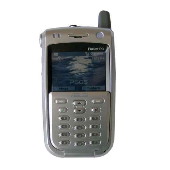
Asus P505 Service Manual
P505
Hide thumbs
Also See for P505:
- Quick start manual (13 pages) ,
- User manual (326 pages) ,
- User handbook manual (80 pages)
Quick Links
See also:
User Manual
Doc. No:
Date: DEC.02, 2004
ASUSTeK COMPUTER
P505 SERVICE GUIDE
Revision: 1
INC.
Grade:
Page:
Rev. Modification
Modify description
Issue
Originator
div.
FIRST RELEASE
RMA-TC
P.P_PAM
Review
Originator
Authorize
by
by
by
Form No : D2-001-11 Rev.01

Related Manuals for Asus P505


Summary of Contents for Asus P505
- Page 1 Doc. No: Date: DEC.02, 2004 ASUSTeK COMPUTER P505 SERVICE GUIDE Revision: 1 INC. Grade: Page: Rev. Modification Modify description Issue Originator div. FIRST RELEASE RMA-TC P.P_PAM Review Originator Authorize Form No : D2-001-11 Rev.01...
-
Page 2: Disassemble Procedure
Doc. No: P505 SERVICE GUIDE ASUSTeK COMPUTER INC. Date: DEC.02, 2004 Rev.: Page: DISASSEMBLE TOOL: P505X1 SCREWDRIVERX1 ASUS P505 DISASSEMBLE PROCEDURE STEPS 1:push the battery lock to right STEPS 2:pull down the bolt and pick up battery... - Page 3 Doc. No: P505 SERVICE GUIDE ASUSTeK COMPUTER INC. Date: DEC.02, 2004 Rev.: Page: STEPS 3:unload the screw in back cover and the Top of P505 STEPS 4:To pull open the plastics case by tool Notice: do not scrape the lacquer...
- Page 4 Doc. No: P505 SERVICE GUIDE ASUSTeK COMPUTER INC. Date: DEC.02, 2004 Rev.: Page: STEPS 5:From another side to open by tool STEPS 6:1.Remove the lines of BT then make button case and MAIN_BD separate. 2.Unload the 3 screws from SD_BD and pull up.
- Page 5 Doc. No: P505 SERVICE GUIDE ASUSTeK COMPUTER INC. Date: DEC.02, 2004 Rev.: Page: Steps7: Unload the screw from MAIN_BD and remove LCD_ FPC. Unload Unload the screw screw Steps 8:1.Pull up MICROPHONE connector. 2.Separate keypad FPC connector and receiver connector.
- Page 6 Doc. No: P505 SERVICE GUIDE ASUSTeK COMPUTER INC. Date: DEC.02, 2004 Rev.: Page: Connect to SD_BD FPC connector Receiver Connector Steps 9:Pick up cursor key Steps 10:1.Unload 2 screws from LCD and push forward then pull LCD up. 2.Take apart TFT BRACKET.
- Page 7 Doc. No: P505 SERVICE GUIDE ASUSTeK COMPUTER INC. Date: DEC.02, 2004 Rev.: Page: Push forward then pull up Steps 12:1.Pull up receiver and unload 2 screws from APKEY HOLDER. 2.Take up APKEY HOLDER and unload 2 screws. Push down...
- Page 8 Doc. No: P505 SERVICE GUIDE ASUSTeK COMPUTER INC. Date: DEC.02, 2004 Rev.: Page: Steps 13:Unload the APKEY_BD and MICROPHONE...
- Page 9 Doc. No: P505 SERVICE GUIDE ASUSTeK COMPUTER INC. Date: DEC.02, 2004 Rev.: Page: Steps 14:1.Press HING down by tweezers and push out by left thumb. 2.Remove the cotton then make KEYPAD_FPC separate with C-PART_ASSY HING...
- Page 10 P505 SERVICE GUIDE ASUSTeK COMPUTER INC. Date: DEC.02, 2004 Rev.: Page: ASUS P505 FABRICATE PROCEDURE- Steps 1:1.Enter the position hole between AP KEY 1,2 and 3,4 KEY 2.Put MICROPNONE into C-PART_ASSY position Notice: there are 2 position of raised on MICROPHONE RUBBER .it need locate in trough of 2 open...
- Page 11 Doc. No: P505 SERVICE GUIDE ASUSTeK COMPUTER INC. Date: DEC.02, 2004 Rev.: Page: Steps 3:1.Lock 1 SCREW to fixed KEYPAD_FPC 2.Lock 2 SCREW to fixed APKEY HOLDER.
- Page 12 Doc. No: P505 SERVICE GUIDE ASUSTeK COMPUTER INC. Date: DEC.02, 2004 Rev.: Page: 3.try to press APKEY and feeling there have clear paragraph Notice: the height of 4 APKEY cannot have clear different Steps 4:1.Wedge into trough by LCD MODULE have FPC side.
- Page 13 Doc. No: P505 SERVICE GUIDE ASUSTeK COMPUTER INC. Date: DEC.02, 2004 Rev.: Page: Steps 5:1.Take one RESET RUBBER. 2.Sheath the RESET RUBBER from up to down into the fixed slice on TFT BRACKET. 3.To paste TACT SWITCH SPONGE on LCD PANEL left...
- Page 14 Doc. No: P505 SERVICE GUIDE ASUSTeK COMPUTER INC. Date: DEC.02, 2004 Rev.: Page: Steps 6:1.It is here to fetch a slice of SD-BOARD FPC SPONGE and stick to SDCARD _ CONNECTOR the back of FPC. 2.On MAIN_BD, SDCAD_CONNECTOR black gear of FPC turns on about 90 degrees.
- Page 15 Doc. No: P505 SERVICE GUIDE ASUSTeK COMPUTER INC. Date: DEC.02, 2004 Rev.: Page: 4. Make SDCARD_ CONNECTOR 2 wings of FPC are close. Notice: Need to do exercises and map 4 and press the black gear that shut CONNECTOR positively...
- Page 16 Doc. No: P505 SERVICE GUIDE ASUSTeK COMPUTER INC. Date: DEC.02, 2004 Rev.: Page: Steps 7:1.Load CONNECTOR of BATT-NI-MH VARTA onto; tear the sticks to the paper and sticks to PHONE JACK right handling. Notice: The end of a thread of CABLE is towards IR, put CABLE in order and wind from CONNECTOR of RECEIVER.
- Page 17 Doc. No: P505 SERVICE GUIDE ASUSTeK COMPUTER INC. Date: DEC.02, 2004 Rev.: Page: Steps 9:1.Load CONNECTOR of RECEIVER onto. Notice: The end of a thread of CABLE is towards PHONE JACK 2.Confirm CONNECTOR of RECEIVER is really packed into. 3.First MAIN_BD transfer the other side, and then MAIN_BD rotate 90, make MAIN_BD LCD CONNECTOR on is close to oneself.
- Page 18 Doc. No: P505 SERVICE GUIDE ASUSTeK COMPUTER INC. Date: DEC.02, 2004 Rev.: Page: Steps 10:1 Is it fetch to take with left hand, MAIN_ BD sets up with C-PART_ASSY presents about 60-90 degrees of ways, inserts FPC of LCD in LCD CONNECTOR first.
- Page 19 Doc. No: P505 SERVICE GUIDE ASUSTeK COMPUTER INC. Date: DEC.02, 2004 Rev.: Page: Notice: Confirm that auxiliary wing of FPC of LCD needs to stick to flat CONNECTOR. Steps 11:1.Put down the MAIN_BD and depend on it in C-PART_ASSY On.
- Page 20 Doc. No: P505 SERVICE GUIDE ASUSTeK COMPUTER INC. Date: DEC.02, 2004 Rev.: Page: sticky tapes of a length of a film, stick to and attach to CONNECTOR of LCD. Steps 12:1.Point it from C-PART_ASSY the bottom is stretched into, assist KEYPAD FPC with the fingertip, and make CONNECTOR on KEYPAD FPC aim at CONNECTOR on MAIN_BD.
- Page 21 Doc. No: P505 SERVICE GUIDE ASUSTeK COMPUTER INC. Date: DEC.02, 2004 Rev.: Page: gently, put into RECEIVER and stick in C-PART _ ASSY On RECEIVER BODGE. 4.CONNECTOR and MAIN_BD of MICROPHONE is combined. Steps 13:1.2 Ribs needing to make the bottom stick to the flat red frame line place while installing MODULE of 6PINFPC.
- Page 22 Doc. No: P505 SERVICE GUIDE ASUSTeK COMPUTER INC. Date: DEC.02, 2004 Rev.: Page: MAIN_BD on TFT BRACKET. Steps 14:1.Of SD_BD the gear of CAMERA MODULE is turned 2.And then insert FPC of CAMERA MODULE smoothly...
- Page 23 Doc. No: P505 SERVICE GUIDE ASUSTeK COMPUTER INC. Date: DEC.02, 2004 Rev.: Page: in the gear and press. Steps 15:1.SD_BD Slot of SD packs D-PART_ASSY into up, first SD_BD right hand enters the card and colludes. 2.And then SD_BD right press, make SD_BD tenon on D-PART_ASSY.
- Page 24 Doc. No: P505 SERVICE GUIDE ASUSTeK COMPUTER INC. Date: DEC.02, 2004 Rev.: Page: Steps 16:1.Take an ANTENNA inserting the aerial hole. 2.Really insert it finally, confirm that the aerial bottom sticks to flat D-PART _ ASSY. 3.Stick to a slice of PCB ESD GASKET-2 on MAIN...
- Page 25 Doc. No: P505 SERVICE GUIDE ASUSTeK COMPUTER INC. Date: DEC.02, 2004 Rev.: Page: Steps 17:1.Take EARPHONE RUBBER in PHONE JACK first 2.Take one PLATE CURSORKEY, there are the directions of 2 localization holes forward, set at CURSORKEY, and then gently extrapolate, until the fact that PLATE CURSORKEY sink to the trough.
- Page 26 Doc. No: P505 SERVICE GUIDE ASUSTeK COMPUTER INC. Date: DEC.02, 2004 Rev.: Page: Steps 18:1.Put into BUTTON RIGHT C-PART_ASSY in the trough, pay attention to directionality, BUTTON RIGHT orient hole open one's mouth the heavy one down, the opening is small up.
- Page 27 Doc. No: P505 SERVICE GUIDE ASUSTeK COMPUTER INC. Date: DEC.02, 2004 Rev.: Page: Steps 19: 1.Insert SPEAKER CONNECTOR in MAIN_BD Notice: The thread is towards SDCARD the direction of FPC, avoid interfering with VIBRATOR 2.Install CONNECTOR and MAIN_BD of BLUETOOTH ANTENNA is combined.
- Page 28 Doc. No: P505 SERVICE GUIDE ASUSTeK COMPUTER INC. Date: DEC.02, 2004 Rev.: Page: Steps 20:1.D-PART_ASSY is it enter DUCKING set, machine of platform first after covering, set push up after entering, make C-PART_ASSY and D-PART_ASSY card colludes and really combines.
- Page 29 Doc. No: P505 SERVICE GUIDE ASUSTeK COMPUTER INC. Date: DEC.02, 2004 Rev.: Page: Steps 21:1.Lock 2 Screws in BATTERY trough. 2.Set up the machine platform straight finally, lock 2 Screws on a top in the machine.