Table of Contents
website http://biz.LGservice.com
e-mail http://www.LGEservice.com/techsup.html
Room Air Conditioner
SERVICE MANUAL
CAUTION
-BEFORE SERVICING THE UNIT, READ THE SAFETY
PRECAUTIONS IN THIS MANUAL.
-ONLY FOR AUTHORIZED SERVICE PERSONNEL.
MODEL : LS-J0761CL / CM / CN / DL
LS-J0761HL / HM / HN
LS-J0762HL / HM / HN
LS-J0763CL / EL / HL
LS-J0820HL
LS-J0821CL / CM
LS-J0822AL
LS-J0962CL / CM / CN
LS-J0962HL / HM / HN / EL
LS-J0963CL / CM / CN / AL /DL
LS-J0964CL / GL / DL / HL / HM / EL
Table of Contents
Troubleshooting

Related Manuals for LG LS-J0761CLCM


Summary of Contents for LG LS-J0761CLCM
-
Page 1: Room Air Conditioner
website http://biz.LGservice.com e-mail http://www.LGEservice.com/techsup.html Room Air Conditioner SERVICE MANUAL CAUTION -BEFORE SERVICING THE UNIT, READ THE SAFETY PRECAUTIONS IN THIS MANUAL. -ONLY FOR AUTHORIZED SERVICE PERSONNEL. MODEL : LS-J0761CL / CM / CN / DL LS-J0761HL / HM / HN LS-J0762HL / HM / HN LS-J0763CL / EL / HL LS-J0820HL... -
Page 2: Table Of Contents
Contents Functions ..........................3 Product Specifications ......................5 Dimensions ..........................7 Refrigeration Cycle Diagram ....................10 Wiring Diagram ........................11 Operation Details ......................... 13 Display Function ........................20 Self-diagnosis Function ....................... 20 Installation ..........................21 Operation ..........................37 Disassembly of the parts (Indoor Unit) ................39 2-way, 3-way Valve ........................ -
Page 3: Functions
Functions Indoor Unit Operation ON/OFF by Remote controller Sensing the Room Temperature • Room temperature sensor. (THERMISTOR) Room temperature control • Maintains the room temperature in accordance with the Setting Temp. Starting Current Control • Indoor fan is delayed for 5 sec at the starting. Time Delay Safety Control •... -
Page 4: Remote Control
Remote Control Operation ON/OFF Operation Mode Selection Cooling Operation Mode.( Auto Operation Mode.( (Cooling (Heating Healthy Dehumidification Operation Mode.( Heating Operation Mode.( model only) model only) Fan Speed Selection (Low) (Med) (High) (CHAOS) Room, Temperature Display : (High:39°C Low:11°C) Temperature Setting HIGH TEMPERATURE Down to 18°C... -
Page 5: Product Specifications
Product Specifications LS-J0761CL LS-J0963CL/CM Model Name LS-J0962CL LS-J0821CL/CM CM/CN/DL AL/DL/CN CM/CN LS-J0822AL LS-J0763CL LS-J0964CL/GL/DL Item Unit Cooling Capacity Btu/h 7,000 9,000 8,000 9,000 Moisture Removal Power Source Ø, V, Hz 1Ø, 220-240V, 50Hz 1Ø 220V, 60Hz 1Ø, 220-240V, 50Hz Indoor Air Circulation /min Outdoor... - Page 6 Product Specifications Model Name LS-J0962HL/HM LS-J0761HL LS-J0762HL/HM/HN LS-J0820HL HN/EL HM/HN LS-J0763HL/EL Item Unit LS-J0964HL/HM/EL 7,000 7,000 8,000 9,000 Cooling Capacity Btu/h 7,300 7,300 8,000 9,300 Heating Capacity Moisture Removal 1Ø, 220-240V, 50Hz Power Source Ø, V, Hz Indoor Air Circulation /min Outdoor Indoor...
-
Page 7: Dimensions
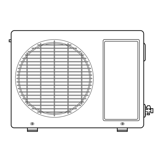
Dimensions (1) Indoor Unit Installation plate Tubing hole cover Left rear piping Right rear piping 80mm ø70mm ø70mm 50mm 7K Btu MODEL 8K Btu 9K Btu Unit... - Page 8 (2) Outdoor Unit Gas side (3-way valve) Liquid side (2-way valve) 7K Btu MODEL 8K Btu 9K Btu(Cooling Only) unit...
- Page 9 (3) Outdoor Unit (9K Btu Heat Pump) Gas side (3-way valve) Liquid side (2-way valve) MODEL 9K Btu Heat Pump unit...
-
Page 10: Refrigeration Cycle Diagram
Refrigeration Cycle Diagram INDOOR UNIT OUTDOOR UNIT CHECK VALVE LIQUID SIDE (Heating Model only) 2-WAY VALVE CAPILLARY TUBE HEAT HEAT EXCHANGE EXCHANGE (EVAPORATOR) (CONDENSER) GAS SIDE REVERSING 3-WAY VALVE ACCUMU VALVE LATOR (Heating Model Only) COOLING COMPRESSOR HEATING MAX. Pipe size(Diameter:Ø) MODEL Piping length Elevation... -
Page 11: Wiring Diagram
Wiring Diagram (1) 7K, 8K, 9K Btu Cooling Only Indoor Unit POWER FORCED MAIN PCB OPERATION AUTO Indoor unit Model Outdoor unit RESTART TRIAC REMOTE LS-J0761CL/DL/CM/CN CONTROL MOTOR OPTION LS-J0821CL/CM THERMISTOR LS-J0822AL LS-J0962CL/CM/CN STEP SH-CAPA. MOTOR LS-J0963CL/CN/AL/DL/CN/CM LS-J0763CL BL/RIBBED LS-J0964CL/GL/DL H.V.B A/CL LIMIT... -
Page 12: Indoor Unit
(2) 7K, 9K Btu Cooling & Heating Indoor Unit Outdoor Unit Outdoor Unit POWER FORCED MAIN PCB OPERATION AUTO COMP. RESTART TRIAC MOTOR REMOTE CONTROL (RD) MOTOR CAPACITOR THERMISTOR RD BL STEP SH-CAPA. MOTOR (RD) (RD) FUSE AC250V/T2A GN/YL (RD) RY-COMP. -
Page 13: Operation Details
Operation Details 1. MAIN UNIT FUNCTION • DISPLAY 1) C/O Model Operation Indicator • On while in appliance operation, off while in appliance pause • Flashing while in disconnection or short in Thermistor (3 sec off / 0.5 sec on) Sleep Timer Indicator •... - Page 14 • While in compressor off, the indoor fan repeats low airflow speed and pause. • While the intake air temp is between compressor on temp. and compressor off temp., 10-min dehumidifica- tion operation and 4-min compressor off repeat. Compressor ON Temp. Setting Temp+0.5°C Compressor OFF Temp.
- Page 15 Fuzzy Operation (C/O Model) • According to the temperature set by Fuzzy rule, when the intake air temp is 0.5°C or more below the setting temp, the compressor is turned off. When 0.5°C or more above the setting temp, the compressor is turned on. Compressor ON Temp Setting Temp + 0.5°C Compressor OFF Temp...
- Page 16 2) Fuzzy Operation for Dehumidification • According to the setting temperature selected by Fuzzy rule, when the intake air temp is 0.5°C or more below the setting temp, the compressor is turned off. When 0.5°C or more above the setting temp, the compressor is turned on.
- Page 17 Off-Timer Operation • When the set time is reached after the time is input by the remote control, the appliance stops operating. • The timer LED is on when the off-timer is input. It is off when the time set by the timer is reached. •...
- Page 18 Jet Cool Mode Operation (C/O Model) • If the Jet Cool key is input at any operation mode while in appliance operation, the Jet Cool mode operates. • In the Jet Cool mode, the indoor fan is operated at super-high speed for 30 min at cooling mode operation. •...
- Page 19 Forced Operation (H/P Model) • To operate the appliance by force in case that the remote control is lost, the forced operation selection switch is on the main unit of the appliance to operate the appliance in the standard conditions. •...
-
Page 20: Display Function
Display Function 1. Heating Model 2. Cooling Model Operation Indicator Operation Indicator • Cooling, Soft Dry, Fan, Heating • Cooling, Soft Dry, Fan Sleep Timer Indicator Sleep Timer Indicator • Sleep Mode • Sleep Mode Timer Indicator Timer Indicator • Timer Mode •... -
Page 21: Installation
Installation 1. Installation of indoor, Outdoor unit 1) Selection of the best location 1. Indoor unit There should not be any heat source or steam • near the unit. More than 5 cm More than • There should not be any obstacles to prevent the 5 cm air circulation. - Page 22 2) Indoor Unit Installation The mounting wall should be strong and solid enough to protect it from the vibration. Installation plate 1.Mount the installation plate on the wall with four Type "A" screws. (if mounting the unit on the concrete wall, consider using anchor bolts.) •...
-
Page 23: Piping And Drainage Of Indoor Unit
2. Piping and Drainage of Indoor Unit 1) Preparation of Piping Pipe cutter 1. Cut the pipes and the cable. • Use the accessory piping kit or the pipes pur- chased locally. Slanted Rough • Measure the distance between the indoor and the outdoor unit. - Page 24 2) Connection of Pipings Installation plate 1. Remove the installation plate • Pull the two '∆' marked portion of bottom of the chassis and pull the installation plate out of chas- sis. Pull Pull 2. Route the drain hose and the indoor tubing. For right rear piping 3.
- Page 25 5. Bend the tubing as shown in the figure and bind the piping, the connecting cables and the drain hose altogether. Conecting Gas side cable • Make a small loop for easy connection later. piping Liquid side piping Drain hose 6.
- Page 26 For left rear piping Installation plate 3. Insert the connecting cables, the drain pipe and connecting piping through the piping hole on the wall. Pull Pull 4. Connect the piping and the indoor tubing, and drain hose and drain pipe and place the drain pipe into the chassis.
- Page 27 6. Wrap the insulation material around the connect- ing portion. CAUTION Take care to arrange the piping, drain hose and Taping cables as the figure 7 page for inserting it into the indoor unit and mount the indoor unit on the installa- Indoor/outdoor tion plate.
- Page 28 3. Connecting Piping and Cable to the outdoor unit 1) Connecting the piping to the Outdoor unit 1. Align the center of the piping and sufficiently tighten the flare nut with fingers. 2. Finally, tighten the flare nut with torque wrench until the wrench clicks.
- Page 29 2) Connection of the cable Outdoor unit 1. Remove the cover control from the unit by loosen- ing the screw. Connect the wires to the terminals on the control Terminal block board individually as the following. (Pillar terminal) Connecting 1) Cooling only type cable Holder for Over...
- Page 30 4. Checking the Drainage and Connecting the cable to Indoor unit 1) Checking the Drainage 1. Remove the Grille from the cabinet. • Set the up-and-down air direction louver to the open position (horizontally) by finger pressure. • Remove the securing screws. •...
- Page 31 2) Connecting of the cable to the indoor unit 1. Connect the wires to the terminals on the con- trol board individually according to the out- door unit connection. • Ensure that the color of the wires of outdoor unit and the terminal No. are the same as the indoor unit.
- Page 32 3) Form the piping 1. Wrap the connecting portion of indoor unit with the Insulation material and secure it with two Plastic Bands.(for the right piping) • If you want to connect an additional drain hose, Taping the end of the drain-outlet should be off the Drain hose ground.(Do not dip it into water, and fix it on the wall to avoid swinging in the wind.)
-
Page 33: Air Purging Of The Piping And Indoor Unit
5. Air Purging of the Piping and Indoor Unit 1) Air purging Terminal block The air remaining which contains moisture in the (pillar terminal) refrigeration cycle may cause a malfunction on the Gas side compressor. 1. Remove the caps from the 2-way and 3-way valves. - Page 34 8. Checking a gas leakage (1) Connect the manifold gauge to the service port of 3-way valve. Measure the pressure. (2) Keep it for 5-10 minutes. Ensure if the pressure indicated on the gauge is as same as that of measured at first time. Liquid side Indoor unit Outdoor unit...
-
Page 35: Pipe Length And The Elevation
6. Pipe length and the elevation Max. Max. Piping Additional Refrig- Capacity Standard Elevation Length erant Length(m) (Btu/h) (g/m) 7~12K Indoor unit Indoor unit Oil trap Outdoor unit Outdoor unit In case more than 5m CAUTION • Capicity is based on standard length and maximum allowance length is the basis of reliability. •... -
Page 36: Test Running
7. Test running 1) Connection of power supply 1. Connect the power supply cord to the inde- Battery Cover pendent power supply. • Circuitbreaker is required. 2. Prepare the remote controller. • Insert two batteries provided. Remove the battery cover from the remote con- troller. -
Page 37: Operation
Operation Name and Function-Remote Control(C/O Model) START/STOP BUTTON Remote Control Operation starts when this button is pressed and stops when the button is pressed again. Signal transmitter ROOM TEMPERATURE SETTING BUTTONS Used to select the room temperature. Transmits the signals INDOOR FAN SPEED SELECTOR to the room air conditioner. - Page 38 Name and Function-Remote Control(H/P Model) START/STOP BUTTON Remote Control Operation starts when this button is pressed and stops when the button is pressed again. Signal transmitter ROOM TEMPERATURE SETTING BUTTONS Used to select the room temperature. Transmits the signals INDOOR FAN SPEED SELECTOR to the room air conditioner.
-
Page 39: Disassembly Of The Parts (Indoor Unit)
Disassembly of the parts (Indoor unit) Warning : Disconnect the unit from power supply before making any checks. Be sure the power switch is set to “OFF”. To remove the Grille from the Chassis. • Set the up-and-down air discharge louver to open position (horizontally) by finger pressure. - Page 40 2. To remove the Control Box. • Remove 2 securing screws. • Pull the control box out from the chassis carefully. 3. To remove the Discharge Grille. • Remove the securing screw. • Pressing the right side of the discharge grille downward slightly, unhook the discharge grille.
- Page 41 • Unhook the tab on the right inside of the chassis at the same time, slightly pull the evaporator toward you until the tab is clear of the slot. 5. To remove the Cross-Flow Fan • Loosen the screw securing the cross-flow fan to the fan motor (do not remove).
- Page 42 LS-J0964HL/J0964HM Warning : Disconnect the unit from power supply before making any checks. Be sure the power switch is set to “OFF”. To remove the Grille from the Chassis • Set the up-and-down air discharge louver to open position (horizontally) by finger pressure. •...
- Page 43 2. To remove the Control Box. • Remove 2 securing screws. • Pull the control box out from the chassis carefully. 3. To remove the Discharge Grille. • Remove the securing screw. • Pressing the right side of the discharge grille downward slightly, unhook the discharge grille.
- Page 44 • Unhook the tab on the right inside of the chassis at the same time, slightly pull the evaporator toward you until the tab is clear of the slot. 5. To remove the Cross-Flow Fan • Loosen the screw securing the cross-flow fan to the fan motor (do not remove).
-
Page 45: 2-Way, 3-Way Valve
2-way, 3-way Valve 2-way Valve (Liquid Side) 3-way Valve (Gas Side) Valve cap Hexagonal wrench (4mm) Open position Flare nut Flare nut Closed position Open position Closed position piping piping Service Service connection connection port cap port To outdoor unit To outdoor unit Works Shaft position... -
Page 46: Air Purging
1. Air purging Required tools : hexagonal wrench, adjustable The air in the indoor unit and in the piping must be wrench, torque wrenches, wrench to purged. If air remains in the refrigeration pipes, it will hold the joints, and gas leak affect the compressor, reduce to cooling capacity, and detector. -
Page 47: Pumping Down
2. Pumping down Liquid side Indoor unit Outdoor unit Open 2-Way valve Gas side Closed 3-Way valve CLOSE CLOSE Purge the air • Procedure (6) Operate the air conditioner at the cooling (1) Confirm that both the 2-way and 3-way valves cycle and stop it when the gauge indicates are set to the open position. - Page 48 1) Re-air purging (Re-installation) Liquid side Indoor unit Closed Outdoor unit 2-Way valve Gas side Closed 3-Way valve Gas cylinder OPEN CLOSE • Procedure (6) Disconnect the charge set and the gas (1) Confirm that both the 2-way valve and the 3- cylinder, and set the 2-way and 3-way valves way valve are set to the closed position.
- Page 49 2) Balance refrigerant of the 2-way, 3-way valves (Gas leakage) Liquid side Indoor unit Outdoor unit 2-Way valve Open Gas side 3-Way valve Open OPEN CLOSE • Procedure (1) Confirm that both the 2-way and 3-way valves are set to the back seat. (2) Connect the charge set to the 3-way valve’s port.
- Page 50 3. Evacuation (All amount of refrigerant leaked) Liquid side Indoor unit Outdoor unit 2-Way valve Open Gas side 3-Way valve Open Vacuum pump OPEN CLOSE • Procedure (1) Connect the vacuum pump to the charge set’s center hose (2) Evacuation for approximately one hour. –...
-
Page 51: Gas Charging
4. Gas Charging (After Evacuation) Liquid side Indoor unit Open Outdoor unit 2-Way valve Gas side Open 3-Way valve Check valve Charging cylinder OPEN CLOSE • Procedure (1) Connect the charge hose to the charging This is different from previous procedures. cylinder. -
Page 52: Cycle Troubleshooting Guide
Cycle Troubleshooting Guide Trouble analysis 1. Check temperature difference between intake and discharge air and operating current. Temp. difference : approx. 0°C • All amount of refrigerant leaked Current : less than 80% of out. Check refrigeration cycle. rated current Temp. -
Page 53: Electronic Parts Troubleshooting Guide
Electronic Parts Troubleshooting Guide 1. Product does not operate at all. (* Refer to Electronic Control Device drawing and Schematic diagram.) Turn off Main Power (After 10 seconds) Turn on Main Power Does "beeping" sound is made from the Indoor Unit? Primarily, the operating condition of Micom is OK. - Page 54 2. The product is not operate with the remote control. Turn on Main Power While the compressor has been stopped, the compressor does not operate owing to the delaying function for 3 minutes after stopped. When the compressor stopped Indoor Fan is driven by a low speed. At this point the wind speed is not controlled by the remote controller.
- Page 55 3. Compressor/Outdoor Fan are unable to drive. Turn on Main Power Operate "Cooling Mode( )" by setting the desired temperature of the remote controller is less than one of the indoor temperature by 1°C at least. When in Air Circulation Mode, Compressor/Outdoor Fan is stopped. Check the sensor for indoor temperature is attached as close as to be effected by the temperature of Heat Exchanger(EVA).
-
Page 56: When Indoor Fan Does Not Operate
4. When indoor Fan does not operate. Turn off Main power Check the connection of CN-MOTOR Check the Fan Motor Check the Fuse(AC250V/T2A) Check the related circuit of indoor Fan Motor. • The pin NO 63 of Micom, and the part for driving TRIAC(the input and output signal of IC01M, PIN NO 2, 15) •... - Page 57 5. When Vertical Louver does not operate. • Confirm that the Vertical Louver is normally geared with the shaft of Stepping Motor. • If the regular torque is detected when rotating the Vertical Louver with hands Normal • Check the connecting condition of CN-U/D Connector •...
- Page 58 6. When Heating does not operate Turn ON Main Power Operate “Heating Mode( )” by setting the desired temperature of the remote control is higher than one of the indoor temperature by 2°C at least. In heating Mode, the indoor fan operates in case the pipe temperature is higher than 28°C.
- Page 59 Turn off Main Power • Check the electrical wiring diagram of outdoor side. • Check the abnormal condition for the component of Compressor/Outdoor Fan Motor, 4 way. • Check the "open" or "short" of connecting wires between indoor and outdoor. -59-...
-
Page 60: Electronic Control Device
Electronic Control Device (1) MAIN P.W.B. ASSEMBLY (2) MAIN P.W.B. ASSEMBLY -60-... - Page 61 (3) DISPLAY ASSEMBLY -61-...
-
Page 62: Schematic Diagram
Schematic Diagram Heat Pump Series -62-... - Page 63 Cooling Only Series -63-...
-
Page 64: Exploded View And Replacement Parts List
Exploded View and Replacement Parts List 1. Indoor Unit 152313 135312 135314 733010 131410 152302 359011 268712 342800 354210 135311 35211B 346810 263230 W0CZZ 147581 352150 146811 267110 249951 264110 268714 -64-... - Page 65 Parts List (Cooling Indoor) PART NO. DESCRIPTION REMARKS LS-J0761CL LS-J0763CL LS-J0761DL LS-J0964DL 131410 CHASSIS ASSEMBLY 3141A20001B 3141A20001D 3141A20001C 135311 GRILLE ASSEMBLY,DISCHARGE(INDOOR) 3531A10005A 3531A10005C 135312 GRILLE ASSEMBLY,FRONT(INDOOR) 3531A10001S 3531A10038N 3831A10038Q 135314 GRILLE ASSEMBLY,INLET SUB 3531A20003N 3531A20068A 3531A20003L 146811 MOTOR ASSEMBLY,STEP 4681AR2727H 152302 FILTER(MECH),A/C 5230AR2630A 152313 FILTER ASSEMBLY,DEODORIZER...
- Page 66 Parts List (Heat Pump Indoor) PART NO. DESCRIPTION REMARKS LS-J0761HL LS-J0762HL LS-J0762HM LS-J0762HN LS-J0763EL LS-J0763HL 131410 CHASSIS ASSEMBLY 3141A20001B 3141A20001D 3141A20001B 3141A20001D 3141A20001C 135311 GRILLE ASSEMBLY,DISCHARGE(INDOOR) 3531A10005A 3531A10005C 3531A10005A 3531A10005C 135312 GRILLE ASSEMBLY,FRONT(INDOOR) 3531A10001R 3531A10001M 3531A10010C 3531A10025D 3531A10038P 3531A10038T 135314 GRILLE ASSEMBLY,INLET SUB 3531A20003M 3531A20003K 3531A20015C 3531A20031D 3531A10047C 3531A20068B 146811...
- Page 67 Parts List (Cooling Indoor) PART NO. DESCRIPTION REMARKS LS-J0962CL LS-J0963AL LS-J0963CL LS-J0821CL LS-J0822AL 131410 CHASSIS ASSEMBLY 3141A20001B 3141A20001C 3141A20001D 3141A20001C 135311 GRILLE ASSEMBLY,DISCHARGE(INDOOR) 3531A10005A 3531A10005C 135312 GRILLE ASSEMBLY,FRONT(INDOOR) 3531A10001S 3531A10001N 3531A10038S 3531A20050P 135314 GRILLE ASSEMBLY,INLET SUB 3531A20003N 3531A20003L 3531A20068D 3531A20068E 146811 MOTOR ASSEMBLY,STEP 4681AR2727H 152302 FILTER(MECH),A/C...
- Page 68 Parts List (Cooling Indoor) PART NO. DESCRIPTION REMARKS LS-J0964CL LS-J0964GL LS-J0963DL LS-J0963CN 131410 CHASSIS ASSEMBLY 3141A20001C 3141A20001B 135311 GRILLE ASSEMBLY,DISCHARGE(INDOOR) 3531A10005C 3531A10005A 135312 GRILLE ASSEMBLY,FRONT(INDOOR) 3531A10038N 3531A10038Q 3531A10001N 3531A10025C 135314 GRILLE ASSEMBLY,INLET SUB 3531A20068A 3531A20003L 3531A20031C 146811 MOTOR ASSEMBLY,STEP 4681AR2727H 152302 FILTER(MECH),A/C 5230AR2630A 152313 FILTER ASSEMBLY,DEODORIZER...
- Page 69 Parts List (Heat Pump Indoor) PART NO. DESCRIPTION REMARKS LS-J0962EL LS-J0964EL LS-J0964HL LS-J0964HM LS-J0962HL LS-J0962HM LS-J0820HL 131410 CHASSIS ASSEMBLY 3141A20001D 3141A20001C 135311 GRILLE ASSEMBLY,DISCHARGE(INDOOR) 3531A10005C 135312 GRILLE ASSEMBLY,FRONT(INDOOR) 3531A10001M 3531A10038P 3531A10038T 3531A10040M 1A10010V 3531A10102A 135314 GRILLE ASSEMBLY,INLET SUB 3531A20003K 3531A10047C 3531A20068B 3531A10041H 3531A20003K 3531A20015T 3531A20003K 146811 MOTOR ASSEMBLY,STEP 4681AR2727H...
- Page 70 Parts List (Cooling Indoor) PART NO. DESCRIPTION REMARKS LS-J0761CM LS-J0761CN LS-J0821CM LS-J0962CM LS-J0962CN LS-J0963CM 131410 CHASSIS ASSEMBLY 3141A20001B 3141A20001B 3141A20001C 3141A20001B 3141A20001B 3141A20001B 135311 GRILLE ASSEMBLY, DISCHARGE(INDOOR) 3531A10005A 3531A10005A 3531A10005C 3531A10005A 3531A10005A 3531A10005A 135312 GRILLE ASSEMBLY, FRONT(INDOOR) 3531A10010B 3531A10025E 3531A10010Z 3531A10010B 3531A10025E 3531A10010B 135314 GRILLE ASSEMBLY, INLET SUB 3531A20015B 3531A20031E 3531A20015Z 3531A20015B 3531A20031E 3531A20015B 146811 MOTOR ASSEMBLY, STEP...
- Page 71 Parts List (Heat Pump Indoor) PART NO. DESCRIPTION REMARKS LS-J0761HM LS-J0761HN LS-J0962HN 131410 CHASSIS ASSEMBLY 3141A20001B 3141A20001B 3141A20001B 135311 GRILLE ASSEMBLY, DISCHARGE(INDOOR) 3531A10005A 3531A10005A 3531A10005A 135312 GRILLE ASSEMBLY, FRONT(INDOOR) 3531A10010C 3531A10025F 3531A10025Y 135314 GRILLE ASSEMBLY, INLET SUB 3531A20015C 3531A20031F 3531A20031U 146811 MOTOR ASSEMBLY, STEP 4681AR2727H 4681AR2727H...
- Page 72 2. Outdoor unit 437210 437212 552111 435511 554031 559010 546810 W0CZZ-1 649950 552116 567502 552202 561410 554160 550140 552203-1 552203-2 430410 -72-...
- Page 73 3. Outdoor unit • 9K Btu Heat Pump 437210 437212 554031 435511 546810 559010 649950 552102-1 552111 5522201 552102-2 552116 W0CZZ 552202 447910 561410 567502 554160 550140 552203-1 430410 552203-2 -73-...
- Page 74 Parts List (Cooling Outdoor) PART NO. DESCRIPTION REMARKS LS-J0761CL LS-J0763CL LS-J0761DL LS-J0964DL 135310 GRILLE ASSEMBLY, FRONT(OUTDOOR) 3531AR2512P 3531AR2512R 430410 BASE ASSEMBLY,WELD(OUTDOOR) 3041AR2415K 435511 COVER ASSEMBLY,CONTROL(OUTDOOR) 4994AR3492B 437212 PANEL ASSEMBLY,REAR(OUTDOOR) 3530AR0058C 3530AR0058B 546810 MOTOR ASSEMBLY,OUTDOOR 4681A20004E 4681A20004F 550140 ISOLATOR,COMP 4H00982E 552102 TUBE,CAPILLARY BEND 5210A30151B 5424AR3582B 552111 TUBE ASSEMBLY,CAPILLARY...
- Page 75 Parts List (Cooling Outdoor) PART NO. DESCRIPTION REMARKS LS-J0962CL LS-J0963AL/DL LS-J0963CL LS-J0821CL LS-J0822AL LS-J0964CL LS-J0964GL LS-J0963CN 135310 GRILLE ASSEMBLY, FRONT(OUTDOOR) 3531AR2512R 3531AR2512T 430410 BASE ASSEMBLY,WELD(OUTDOOR) 3041AR2415K 435511 COVER ASSEMBLY,CONTROL(OUTDOOR) 4994AR3492B 437212 PANEL ASSEMBLY,REAR(OUTDOOR) 3530AR0058B 546810 MOTOR ASSEMBLY,OUTDOOR 4681A20004F 4681A20004G 4681A20004F 550140 ISOLATOR,COMP 4H00982E 552102 TUBE,CAPILLARY BEND...
- Page 76 Parts List (Cooling Indoor) PART NO. DESCRIPTION REMARKS LS-J0761CM LS-J0761CN LS-J0821CM LS-J0962CM LS-J0962CN LS-J0963CM 430410 BASE ASSY, WELD[OUTDOOR] 3041AR2415K 3041AR2415K 3041AR2415K 3041AR2415K 3041AR2415K 3041AR2415K 435511 COVER ASSY, CONTROL(OUTDOOR) 4994AR3492B 4994AR3492B 4994AR3492B 4994AR3492B 4994AR3492B 4994AR3492B 437210 GRILLE ASSY, FRONT(OUTDOOR) 3531A20051F 3531AR2512S 3531AR2512R 3531AR2512M 3531AR2512W 3531AR2512M 437212 PANEL ASSY, REAR(OUTDOOR) 3530AR0058C 3530AR0058C 3530AR0058B 3530AR0058B 3530AR0058B 3530AR0058B...
- Page 77 Parts List (Heat Pump Outdoor) PART NO. DESCRIPTION REMARKS LS-J0761HL LS-J0762HL LS-J0762HM LS-J0762HN LS-J0763HL LS-J0763EL LS-J0820HL 135310 GRILLE ASSEMBLY, FRONT(OUTDOOR) 3531AR2512P 3531A20051N 3531AR2512N 3531AR2512W 3531AR2512R 430410 BASE ASSEMBLY,WELD(OUTDOOR) 3041AR2415K 435511 COVER ASSEMBLY,CONTROL(OUTDOOR) 4994AR3492B 437212 PANEL ASSEMBLY,REAR(OUTDOOR) 3530AR0058C 546810 MOTOR ASSEMBLY,OUTDOOR 4681A20004E 4681A20004G 550140 ISOLATOR,COMP...
- Page 78 Parts List (Heat Pump Outdoor) PART NO. DESCRIPTION REMARKS LS-J0962EL LS-J0964EL LS-J0964HL LS-J0964HM LS-J0962HL LS-J0962HM 430410 BASE ASSEMBLY,OUTDOOR 3041A20008K 435511 COVER ASSEMBLY,CONTROL(OUTDOOR) 3551A30023E 437210 PANEL ASSEMBLY,FRONT(OUTDOOR) 3721A20027A 437212 PANEL ASSEMBLY,REAR(OUTDOOR) 3721A20026B 447910 BARRIER ASSEMBLY,OUTDOOR 4791A30002B 546810 MOTOR ASSEMBLY,OUTDOOR 4681A20004J 550140 ISOLATOR,COMP 4H00982E 552102-1 TUBE,CAPILLARY BEND 5424AR7208L...
- Page 79 Parts List (Heat Pump Indoor) PART NO. DESCRIPTION REMARKS LS-J0761HM LS-J0761HN LS-J0962HN 430410 BASE ASSEMBLY, WELD[OUTDOOR] 3041AR2415K 3041AR2415K 3041A20008K 435511 COVER ASSEMBLY, CONTROL(OUTDOOR) 4994AR3492B 4994AR3492B 3551A30023E 437210 GRILLE ASSEMBLY, FRONT(OUTDOOR) 3531AR2512M 3531AR2512V 3721A20027A 437212 PANEL ASSEMBLY, REAR(OUTDOOR) 3530AR0058C 3530AR0058C 3721A20026B 447910 BARRIER ASSEMBLY, OUTDOOR 4791A30002B 546810 MOTOR ASSEMBLY, OUTDOOR...
- Page 80 January, 2002 P/No.: 3828A30033B Printed in Korea...