
Related Manuals for Kenwood CK 231 DF


Summary of Contents for Kenwood CK 231 DF
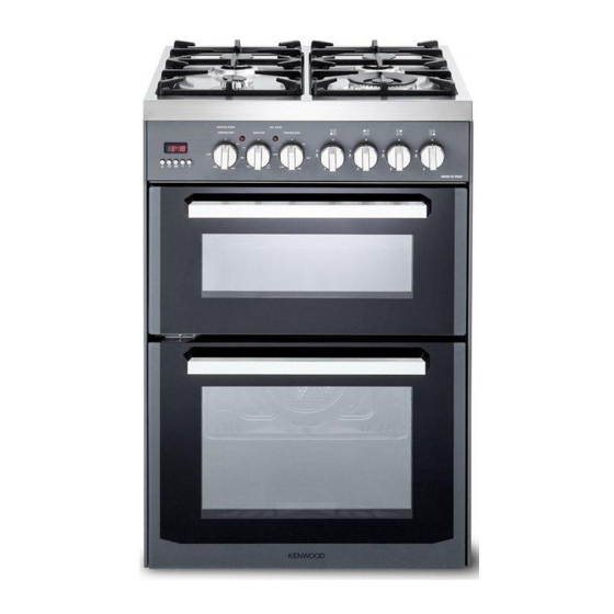
- Page 1 GAS COOKER with ELECTRIC DOUBLE OVEN CK 231 DF model Instructions for use - Installation advice Before operating this cooker, please read these instructions carefully...
-
Page 2: Table Of Contents
CONTENTS Page Number Introduction . . . . . . . . . . . . . . . . . . . . . . . . . . . . . . . . . . . . . . . . . . . . . . . 3 Important Safeguards &... -
Page 3: Introduction
Dear Customer, Thank you for purchasing the Kenwood CK 231 DF dou- ble oven dual fuel cooker . The safety precautions and recommendations listed be- low are for your own safety and that of others . They will also provide a means by which to make full use of the features offered by your appliance . -
Page 4: Important Safeguards & Recommendations
IMPORTANT SAFETY PRECAUTIONS AND RECOMMENDATIONS IMPORTANT: This appliance is designed and manufactured solely for the cooking of domestic (household) food and is not suitable for any non domestic application and therefore should not be used in a commercial environment. The appliance guarantee will be void if the appliance is used within a non domestic environment i.e. - Page 5 • Do not touch the appliance with wet or damp hands (or feet) . • Do not use the appliance whilst in bare feet . • If you should decide not to use this appliance any longer (or decide to substitute another model), before disposing of it, it is recommended that it be made inoperative in an appropriate manner in accordance to health and environmental protection regulations, ensuring in par-...
- Page 6 • WARNING: Danger of fire: do not store items on the cooking surfa- ces . • WARNING: When correctly installed, your product meets all safety requirements laid down for this type of product category . However special care should be taken around the rear or the underneath of the appliance as these areas are not designed or intended to be tou- ched and may contain sharp or rough edges, that may cause injury .
-
Page 7: Cooking Hob
1 - COOKING HOB Fig . 1 .1 GAS BURNERS Auxiliary burner (A) 1,00 kW Semi-rapid burner (SR) 1,75 kW Triple-ring burner (TR) 3,50 kW Notes: • The electric ignition is incorporated in the knobs . • The appliance has a safety valve system fitted, the flow of gas will be stopped if and when the flame should accidentally go out. -
Page 8: Control Panel
2 - CONTROL PANEL Fig . 2 .1 Controls description Front right burner control knob Rear right burner control knob Rear left burner control knob Front left burner control knob Conventional oven temperature knob (Top oven) Conventional oven function selector knob (Top oven) Fan oven switch and temperature knob (Bottom main oven) Electronic programmer (main oven only) Pilot lamps:... -
Page 9: Use Of Hob Burners
3 - USE OF THE HOB BURNERS GAS BURNERS Gas flow to the burners is adjusted by tur- ning the knobs (illustrated in fig. 3.1) which control the safety valves . Turning the knob, so that the indicator line points to the symbols printed on the panel, achieves the following functions: - symbol closed valve maximum - symbol aperture or flow... - Page 10 LIGHTING THE BURNERS CHOICE OF THE BURNER To ignite the burner, the following instruc- On the control panel, near every knob the- tions are to be followed: re is a diagram that indicates which burner is controlled by that knob . Press in the corresponding knob and The suitable burner must be chosen accor- turn counter-clockwise (fig. 3.2) to the...
- Page 11 CORRECT USE OF THE TRIPLE-RING BURNER The flat-bottomed pans are to be placed directly onto the pan-support. When using a WOK you need to place the supplied stand in the burner to avoid any faulty operation of the triple-ring burner (Figs . 3 .4a - 3 .4b) . IMPORTANT: The special grille for wok pans (fig. 3.4b) MUST BE PLACED ONLY over the pan-rest for the triple-ring burner .
-
Page 12: Top Conventional Electric Oven
4 - TOP CONVENTIONAL ELECTRIC OVEN WARNING: Attention: The oven door becomes The door is hot, use the handle. very hot during operation. Keep children away. ATTENTION - MOST IMPORTANT Pay special attention not to touch the GENERAL FEATURES hot heating element inside the oven cavity. - Page 13 TEMPERATURE KNOB (fig. 4.1) This only sets the cooking temperature but does not switch the oven on . Rotate clockwise until the required temperature is reached (from 50°C to the maximum position, 250°C) . The light above the knob will illuminate when the oven is switched on and turns off when the oven reaches the correct temperature .
-
Page 14: Bottom Main Oven
5 - BOTTOM MAIN OVEN Attention: The oven door becomes very hot during operation. Keep children away. SWITCH TEMPERATURE SELECTOR Turn the selector knob (fig. 5.1) to the re- quired function . OFF - as per fig. 5.1 The oven light is switched on . The fan operates without the heating element, this function Fig . -
Page 15: Cooking Guide
6 - OVEN TEMPERATURE GUIDE Electric oven temperature Cooking process Oven heat Gas mark °C °F Keeping food hot, very cool ½ milk puddings Egg custards cool Rich fruit cakes, cool braising Low temperature moderate roasting, shortbread Victoria sandwich, plain fruit cake, moderate baked fish Small cakes, choux... -
Page 16: Electronic Programmer
ELECTRONIC PROGRAMMER (BOTTOM MAIN OVEN ONLY) The electronic programmer is a device which groups together the following functions: • 24 hours clock with illuminated display • Timer (up to 23 hours and 59 minutes) • Program for automatic oven cooking •... -
Page 17: Manual Operation
SETTING TIME OF DAY MANUAL OPERATION (fig. 7.2) The programmer is provided with an elec- To use the oven manually, i .e . without the tronic clock with luminous figures showing programmer, you must cancel the flashing the hour and minutes . A by pressing the two buttons The first time the oven is connected up to multaneously (the letter A will go out and the electricity supply and after a power cut, the symbol will come on) . -
Page 18: Minute Minder
MINUTE MINDER AUDIBLE SIGNAL The minute counter function consists sim- The audible signal sounds at the end of a ply of an acoustic signal which can be set minute minder cycle or of a cooking pro- for a maximum of 23 hours 59 minutes . gramme for a period of 7 minute . - Page 19 SEMI - AUTOMATIC COOKING The oven will come on immediately and when the set time or programmed end of This automatically switches the oven off cooking time expires, it will automatically after the required cooking time . There are switch off . two methods of semi-automatic cooking: During cooking the letter A and the symbol remains on;...
- Page 20 AUTOMATIC COOKING Set the cooking temperature and fun- ction via the function selector and ther- To cook in the oven in automatic mode mostat knob (see specific chapters). follow the instructions below: The oven is now programmed and Set the cooking time everything will work automatically; the Set the end of cooking time oven will come on as required and fi- Set the cooking temperature and...
-
Page 21: Cleaning And Maintenance
8 - CLEANING AND MAINTENANCE GENERAL ADVICE CLEANING • Before you begin cleaning, you Stainless steel hob: Spillage on • must ensure that the appliance is the hob can usually be removed by switched off at the cooker switch. a damp soapy cloth . More obstinate •... - Page 22 BURNERS • Inside of oven: The oven should always be cleaned after use when it They can be removed and washed with has cooled down . The cavity should be soapy water only . cleaned using a mild detergent solu- They will remain always perfect if cleaned tion and warm water .
- Page 23 Fig . 8 .1 Fig . 8 .2 Fig . 8 .3 Fig . 8 .4 Fig . 8 .5...
- Page 24 ASSEMBLY AND DISMANTLING OF THE SIDE RUNNER FRAMES • Fit the side runner frames into the ho- les on the side walls inside the oven (Fig . 8 .6, 8 .7) . • Slide into the guides, the shelf and the tray (fig. 8.8).
- Page 25 OVEN DOOR Type A Fig. 8.10a REMOVING THE OVEN DOOR The oven door can easily be removed as follows: • Open the door to the full extent (fig. 8 .10a) . • Attach the retaining rings to the ho- oks on the left and right hinges (fig. 8 .10b) .
-
Page 26: Door Assembly
OVEN DOOR Type B REMOVING THE OVEN DOOR The oven door can easily be removed as follows: • Open the door completely . • Push down the lever “L” (fig. 8.11a) and, keeping it in this position, slowly close the door in order to block the hinge . -
Page 27: Advice For The Installer
Advice for the installer IMPORTANT • The appliance is designed and approved for domestic use only and should not be installed in a commercial, semi commercial or communal environment . Your product will not be guaranteed if installed in any of the above environments and could affect any third party or public liability insurances you may have. -
Page 28: Installation
9 - INSTALLATION This cooker has class “2/1” overheating protection so that it can be installed next to a cabinet. If the cooker is installed adjacent to furniture which is higher than the gas hob cooktop, a gap of at least 50 mm must be left between the side of the cooker and the furniture . The walls and kitchen furniture surrounding the appliance must be made of non-flammable material . - Page 29 ANTI-TILT BRACKET Important! To restrain the appliance and prevent it tipping accidentally, the anti-tilt bracket sup- plied must be fitted according to the instructions below. To fit the anti-tilt bracket: After you have located where the cooker is to be positioned, mark on the wall and on the floor the place where the four screws of the anti-tilt bracket have to be fitted.
-
Page 30: Provision For Ventilation
PROVISION FOR VENTILATION • The appliance should be installed into a room or space with an air supply in accordan- ce with BS 5440-2: 2000 . • For rooms with a volume of less than 5m - permanent ventilation of 100 cm free area will be required . -
Page 31: Gas Connection
Installation and service of any gas product must be made by a suitably qualified and registered person competent on the type of product being installed or serviced and holding a valid certificate of competence for the work being carried out. Currently the proof of competence is the Accredited Certification Scheme (ACS) or N/SVQ that has been aligned to the ACS . It is also a requirement that all businesses or self employed installers are members of a class of person approved by the Health and Safety Executive . - Page 32 Installation to Natural Gas Installation to Natural Gas must conform to the Code of Practice, etc . The supply pressure for Natural Gas is 20 mbar . The installation must conform to the relevant British/European Standards . Installation to LP Gas When operating on Butane gas a supply pressure of 28-30 mbar is required .
- Page 33 Gas connection (figs. 10.2, 10.3, 10.4) • The gas supply must use the nearest gas inlet pipe which is located at the left or the right hand side at the rear of the appliance . • IMPORTANT: Check the correct positioning of the male connector as per pictures and always operate using two suitable spanners.
- Page 34 IMPORTANT PRESCRIPTIONS FOR GAS CONNECTION Rear wall Fig. 10.3 Suggested area for gas mains connection Fig. 10.4...
- Page 35 CONVERSION TO NATURAL GAS OR TO LPG REPLACEMENT OF THE INJECTORS Auxiliary and If the injectors are not supplied they can Semi-rapid be obtained from the After-Sales Service. burners Select the injectors to be replaced accor- ding to the “Table for the choice of the injectors”...
- Page 36 TABLE FOR THE CHOICE OF THE INJECTORS Cat: 2H3+ G30 28-30 Natural Gas mbar G20 20 mbar Nominal Reduced G31 37 mbar BURNERS power power [kW] [kW] Ø Ø injector injector [1/100 mm] [1/100 mm] Auxiliary (A) 1,00 0,30 72 (X) Semi-rapid (SR) 1,75 0,45...
-
Page 37: Electrical Section
11 - ELECTRICAL INSTALLATION IMPORTANT: The appliance must be installed in accordance with the manufactu- rer’s instructions. Incorrect installation, for which the manufacturer accepts no re- sponsibility, may cause damage to persons, animals and property. The connection of the appliance to earth is mandatory. The manufacturer declines all responsibility for any inconvenience resulting from the inobservance of this condition. -
Page 38: Power Supply
ELECTRICAL FEEDER CABLE CONNECTION WARNING: The power supply cable must be connected only by an authorised servi- ce agent in order to avoid a hazard. If the power supply cable is damaged, it must be replaced only by an authorised service agent in order to avoid a hazard. -
Page 39: After Sales Service
12 - GUARANTEE Your new “KENWOOD” product comes with 12-month guarantee covering all parts and labour . If your appliance proves to be defective as a result of faulty materials or workmanship during the guarantee period, these parts will be repaired or replaced free of charge . - Page 40 The manufacturer cannot be held responsible for possible inaccuracies due to printing or transcription errors in the present booklet . The manufacturer reserves the right to make all modifications to its products deemed necessary for manufacture or commercial reasons at any moment and without prior notice, without jeopardising the essential functional and safety characteristics of the appliances . Code: 1104328 - ß2...