Table of Contents
Quick Links
See also:
User Manual
Table of Contents

Related Manuals for GE D20MX


Summary of Contents for GE D20MX
- Page 1 Digital Energy D20MX Processor Instruction Manual 994-0140 Version 1.4x Revision 1 GE Information...
-
Page 2: Copyright Notice
GE Digital Energy Copyright Notice © 2012 - 2014, General Electric Company. All rights reserved. The information contained in this online publication is the exclusive property of General Electric Company, except as otherwise indicated. You may view, copy and print documents and graphics incorporated in this online publication (the “Documents”) subject to the following: (1) the Documents may be used solely for personal, infor-... -
Page 3: Table Of Contents
Safety words and definitions..................9 PRODUCT SUPPORT Search technical support ...................11 Contact customer support ..................11 Product returns......................12 Upgrade your D20MX processor firmware ..............12 BEFORE YOU START Safety precautions ......................13 Warning symbols ............................14 Regulatory compliance information ................15 CE Mark compliance ............................ 15 Product overview......................15... - Page 4 TABLE OF CONTENTS INSTALLING THE D20 chassis layouts .....................33 Installation steps ......................35 D20MX Retrofitting the D20MX in an existing D20 ..............37 Required tools and materials..................39 Grounding the D20MX ....................39 Unpacking the D20MX ....................39 Package contents ............................40 Connecting the power supply ..................40 CONNECTING TO Cabling overview ......................41...
- Page 5 Updating D20/D200 configurations to use the D20MX firmware definition with ConfigPro......................83 Updating a D20 configuration to use the D20MX firmware definition with ConfigPro 83 Updating a D200 configuration to use the D20MX firmware definition with ConfigPro .. Software (feature) licensing ..................87 USING THE D20MX Front panel LEDs ......................91...
- Page 6 PROTECTION FREQUENTLY ASKED Questions and answers.................... 113 QUESTIONS USING CONFIGPRO Transferring D20 configurations to the D20MX........... 118 WITH D20MX Configuration file in project directory....................130 Downloading a D20MX configuration..............131 Local [serial] transfer of configuration .....................131 Remote [secure] transfer of configuration ..................137 Application definition files and default configurations........
-
Page 7: About This Document
Related other manufacturers’ products, such as protective relays and communications equipment Additional documentation For the most current version of the D20MX Hardware User's Manual, please download a copy from: http://www.gedigitalenergy.com/app/ViewFiles.aspx?prod=d20mx&type=3 For further information about the D20MX, refer to the following documents. -
Page 8: How To Use This Manual
ABOUT THIS DOCUMENT How to use this manual This manual describes how to install the D20MX and get it up and running for the first time. Procedures are provided for all component options available for the D20MX. The components included in your D20MX depend on what was ordered for your substation application. -
Page 9: Safety Words And Definitions
Indicates a hazardous situation which, if not avoided, could result in death or serious injury. Indicates a hazardous situation which, if not avoided, could result in minor or moderate injury. Indicates practices that are not related to personal injury. D20MX INSTRUCTION MANUAL GE INFORMATION... - Page 10 ABOUT THIS DOCUMENT GE INFORMATION D20MX INSTRUCTION MANUAL...
-
Page 11: Product Support
D20MX Processor Product Support Product Support If you need help with any aspect of your GE Digital Energy product, you have a few options. Search technical support The GE Digital Energy Web site provides fast access to technical information, such as manuals, release notes and knowledge base topics at: http://www.gedigitalenergy.com... -
Page 12: Product Returns
You are sent the RMA number and RMA documents via fax or e-mail. Once you receive the RMA documents, attach them to the outside of the shipping package and ship to GE. Product returns are not accepted unless accompanied by the Return Merchandise Authorization number. -
Page 13: Before You Start
The D20MX is capable of consolidating data from multiple slave devices connected through communication channels (DCA: Data Collection Applications) and D20 Input / Output Modules in a single database. The D20MX can execute local logic, aggregate data, process data through one of multiple applications (DTA: Data Translation Applications) and report data upstream to master stations through different server protocols (DPA: Data Processing Applications). -
Page 14: Warning Symbols
• If the D20MX is used in a manner not specified in this manual, the protection provided by the equipment may be impaired. • Changes or modifications made to the unit not authorized by GE Digital Energy could void the warranty. -
Page 15: Regulatory Compliance Information
Consult the manufacturer or field service technician for help Product overview The D20 is a standalone remote terminal unit (RTU). It consists of a D20MX processor board, power supply, optional termination panels, and optional communications equipment in a 3U tall, 19-inch wide chassis. These components, combined with software applications running on the D20MX, form the D20 RTU System. -
Page 16: D20Mx Processor
Appendix A, Standards & Protection for the complete listing. The D20MX can be retrofitted into either a D20 3U single-node VME chassis or D20 3U non- VME chassis. In a single-node VME chassis, this one processor module replaces the previous D20 M, M++, ME, and MEII CPU cards. -
Page 17: D20Mx Applications
The Quantum Meter Scanner DCA obtains data from one or more Quantum Meters via the DNP interface. A023N CDC Type I DPA for D20MX The CDC Type I DPA emulates a CDC Type I RTU A026-1 Communication Reports on the state of communications... - Page 18 DI points in the alarm state exceed the group threshold value. A113N PSR DCA for D20MX Programmable Synchrocheck Relay (PSR) DCA acts as a data concentrator for several remote PSRs. The DCA and remote PSRs function as a remote synchronous closure controller.
- Page 19 B008-1 System Point Database Maintains the database of system points in the RTU. B012N IRIG-B DCA for D20MX Provides Universal Time Coordination (UTC) using the IRIG-B pulse frame, as specified by IRIG Standard 200-04 September 2004 Edition. B013 DNP V3.00 Data Link...
- Page 20 D2X Classic Applications Advanced Automation Applications The license group is an option in the D20MX order code. Refer to Table 8 and Table 9 for details. Ordering a D20MX with a particular license group option enables all applications in that group to run on the D20MX.
-
Page 21: Firmware/Fpga Versions
S055-0 D20AC Peripheral Board (supports B003) D20AC Peripheral Board Code Firmware/FPGA versions Refer to D20MX Release Notes (MIS-0095) available on the D20MX Documentation CD (GE part number 588-0075). D20 chassis For a detailed description of the D20 chassis options and components, refer to the Familiarization chapter in the D20/D200 Installation and Operation Guide, 994-0078. - Page 22 CHAPTER 1: BEFORE YOU START D20 non-VME The D20 non-VME single-slot chassis consists of the following: • D20MX processor board • Modem slots • Power supply with switch and fuses; see Figure 1. Figure 1: D20 non-VME chassis - power supply switch and fuses...
- Page 23 The D20 VME-compatible chassis (see Figure 3) can support one D20MX main board. When using the D20MX in a VME chassis, the 0 V ground wire must be used. Figure 3: D20 VME chassis - power supply switch and fuses...
-
Page 24: Power Supply
Power supply The chassis-mounted power supply modules are switch-mode converters that provide output power for the D20MX processor board, VME cards, modems and D20 Peripheral I/O modules, as required. A redundant power supply can be installed to provide fail-over protection to ensure continuous power to the D20. -
Page 25: Modems
300 to 1200 baud asynchronous operation on unconditioned lines and supports the majority of SCADA/EMS applications. It is available in a 3U (GE part number 520-0120) vertical mount configuration in the D20 chassis; the 19 inch rack mount (GE part number 520-0090) version is currently not supported. -
Page 26: Ordering Guide
CHAPTER 1: BEFORE YOU START Ordering guide The latest D20MX Processor ordering guide is available on the GE Digital Energy website: http://www.gedigitalenergy.com/multilin/energy/catalog/D20MX.htm You can select the required options from the available Product Option items. The Order Code automatically updates as each option is selected. -
Page 27: D20Mx Upgrade Kits
CHAPTER 1: BEFORE YOU START D20MX upgrade kits Table 9 provides the available D20MX upgrade kits and spare kit (D20MX CPU only) Order Guide. Order GE part number 588-0082: SGConfig Setup Software DVD if required. Table 9: D20MX upgrade kits... - Page 28 CHAPTER 1: BEFORE YOU START Table 10 lists the parts provided in each D20MX upgrade kit. Table 10: Upgrade kit parts Part Number Part Description 526-3001 D20MX CPU non VME 2x10/100/1000 BaseTX 526-3003 D20MX CPU non VME 2x100 BaseFX (Front Access)
-
Page 29: Product Specifications
CHAPTER 1: BEFORE YOU START Product specifications The D20MX adheres to the following system, communications, electrical, physical and environmental specifications. Additional Standards and Protection are listed in Appendix A, Standards & Protection. System Processor 667 MHz embedded PowerQUICC II Pro... - Page 30 0.7 kg (1.65 lb) Fiber card weight 0.2 kg (0.35 lb) Battery shipping The D20MX does not contain a battery and is therefore not affected by restrictions US DOT or ICAO shipping restrictions. Material/Finish Galvannealed steel with black power coat Kit package Length: 49.5 cm (19.5 in.)
-
Page 31: Storage Recommendations
Maximum altitude: 12192 m [40,000 feet] above sea level Do not store the D20MX above 60°C for extended periods of time as this shortens the life of the super capacitor and reduces the backup time of the real time clock. - Page 32 CHAPTER 1: BEFORE YOU START GE INFORMATION D20MX INSTRUCTION MANUAL...
-
Page 33: Installing The D20Mx
Grounding the D20MX and connecting the power supply D20 chassis layouts Installation of the D20MX can be performed with one of three D20 chassis layouts; see “Installation steps” on page 35. The D20 non-VME chassis front panel layouts for the D20MX upgrade kits comprise: •... - Page 34 D20MX cover plate D20MX processor D20MX cover plate filler Protective earth D20 power supply terminal Figure 7: D20 chassis front panel - D20MX with front fiber optic connectors D20 chassis D20MX cover plate D20MX processor D20MX cover plate filler Protective earth...
-
Page 35: D20Mx Installation Steps
Installation steps The D20MX can be installed in a non-VME (GE part number 500-0305) or VME (GE part number 500-0280) D20 chassis. If you are retrofitting an existing D20 device, See section: “Retrofitting the D20MX in an existing D20” on page 37. - Page 36 10. Attach any required communication cables to the connectors on the front panel of the D20MX or the backplane of the D20 chassis. 11. If the D20MX is being installed in a VME chassis, connect the 0 V cable (part number 975-1237): 11.1.
-
Page 37: Retrofitting The D20Mx In An Existing D20
100BASE-FX to 10BASE-FL media converter. The D20MX can be installed in a VME chassis or a non-VME chassis. See section: “D20MX upgrade kits” on page 27 for a list of available upgrade kits and the parts provided within each kit. - Page 38 D20MX PCB D20 Chassis - view through top panel If the D20MX is being installed in a VME chassis, connect the 0 V cable (part number 975-1237): 8.1. Connect the bare end of the 0 V cable wire to the O V connector on the WESTERM terminal block TB2-9.
-
Page 39: Required Tools And Materials
Do not power up the D20 before establishing a proper protective earth connection. Unpacking the D20MX Carefully remove the D20MX from its packaging. Visually inspect the unit to ensure it has not sustained any visible damage during transit. If there are visible signs of damage, report it immediately to the carrier. -
Page 40: Package Contents
• GE Digital Energy D20MX Documentation CD (GE part number 588-0075 V14X) Verify that you have received all items. GE parts include a unique number, typically in the format XXX-XXXX, that can be used as a reference. Connecting the power supply The D20MX processor board is supplied power through the WESTERM D20M+ SS backplane. -
Page 41: Connecting To Devices And Networks
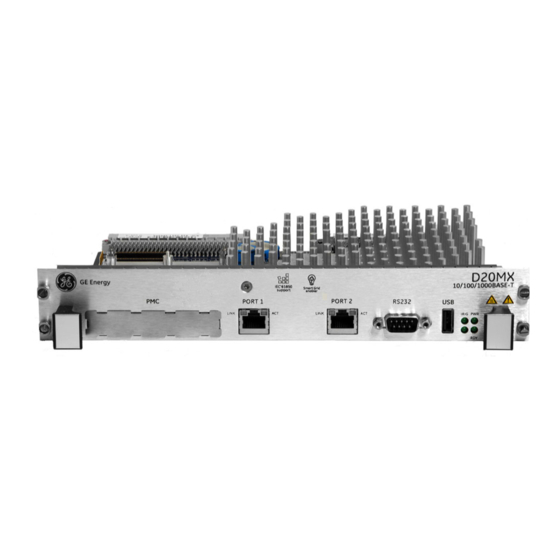
Rear access Fiber optic connectors on a fiber optic daughter card; see Figure 16. The optic daughter card can be either a D20MX dual 100 BASE-FX ST Media Interface Card or a D20MX dual 100 BASE-FX LC Media Interface Card. - Page 42 Port 1 Port 2 supported) LEDs The D20MX can be used with an ST connector Fiber Optic card or an LC connector Fiber Optic card. Figure 16: D20MX front panel and fiber optic card with rear access fiber optic connectors D20 chassis back view –...
-
Page 43: General Cabling Requirements
(TXD, RXD, RTS#, CTS#, DCD#) DTE serial ports, compliant to ANSI/TIA-232 and TIA/EIA-694 specifications and are hosted by UARTs. The D20MX is tested with all 7 serial ports running at 19200 baud with 20% CPU utilization. Refer to application configuration guides for supported baud rates and for data bits. -
Page 44: Peripherals
Peripherals Peripheral I/O modules are intelligent modules containing an on-board microprocessor. They are configured as slaves to the D20MX processor board. In this way, specific I/O processing is distributed throughout the RTU to the appropriate I/O module. There are five types of I/O peripherals: •... -
Page 45: Twisted-Pair Ethernet (For 526-3001 Only)
Plug network cables into the D20MX twisted-pair Ethernet ports. to network devices If the D20MX is deployed in the presence of strong RF energy in the 110 MHz - 125 MHz band, such as airport ILS localizers or aviation radio transmitters, it is recommended that shielded twisted-pair Ethernet cables be used. -
Page 46: Fiber Optic Ethernet (For 526-3003 And 526-3005Lf Only)
Fiber optic Ethernet (for 526-3003 and 526-3005LF only) The 100BASE-FX variant of the D20MX (GE part numbers 526-3003 and 526-3005) can connect to one or two networks through two fiber-optic Ethernet connections. The data rate on each port is 100 Mbps. -
Page 47: Lan Redundancy
When the primary port (that is, port 1) receives no signal, or detects a fault signal from the remote link partner, the D20MX switches to the secondary port (that is, port 2) if it has a valid link. The D20MX reverts to the primary port if the primary link is restored or no signal is present on the secondary port. - Page 48 When transferring a redundant D20/D200 in a ConfigPro or SGConfig project configuration to a D20MX ensure the new D20MX standby IP addresses do not conflict with other devices in the project. If they do, you may disable the standby IP addresses or reassign them as described in the previous paragraph.
- Page 49 CCU B, LAN B FAC_DEFBB The D20MX can be in one of five modes as defined in Table 19. You can find the current mode of the D20MX by navigating to the SHELL in WESMAINT II+ and typing the command el.
-
Page 50: Rs-232
Terminal Emulator is an example of a suitable terminal emulation program. The RS-232 port is connected to the D20MX front panel and is also routed to the rear panel as (COM0). The D20MX can be ordered from the factory with either 9600 or 19200 bps. To change the baud rate of the RS-232 port to 19200, type JBAUD 19200 in the D20M SHELL. - Page 51 Figure 20: Redundant D20 system - If CCU A fails To Field Equipment RS-232 Switch Panel CCU A Serial CCU B Serial Communications Communications RS-232 Switch Monitor and Control CCU A CCU B (F ailed) (Active) Inter-CCU Communications D20MX INSTRUCTION MANUAL GE INFORMATION...
-
Page 52: Failover Sequence
Pins 4 on switch panel connectors J2 through J9 are tied together and to the panel’s power supply. Any loading from field devices on these pins, loads the RS-232 panel power supply and should be taken into consideration when sizing power supplies. GE INFORMATION D20MX INSTRUCTION MANUAL... -
Page 53: Rs-232 Switch Panel Operation
The CCU A/CCU B LED indicator indicates which unit has been activated. Redundancy wiring diagrams Figure 22 illustrates how to wire the D20MX units and RS-232 switch panels to enable system redundancy: The D20MX watchdog (control) port, heartbeat (ping) port, and serial port assignments are software configurable. - Page 54 CHAPTER 3: CONNECTING TO DEVICES AND NETWORKS Figure 22: Redundancy wiring - single RS-232 switch panel GE INFORMATION D20MX INSTRUCTION MANUAL...
-
Page 55: Powering-Up And Testing
Before any of the tests and procedures in this section can be performed, a valid configuration file must be loaded into the D20MX NVRAM. If you have replaced the main board of the D20MX, then you need to restore the configuration file so that diagnostic tests can be performed. -
Page 56: Terminal Emulation
“Set up a PC to act as a WESMAINTII+ terminal”. See page 57. “Power up the D20MX” on page 57. See page 57. Result: The D20MX automatically runs the Online Start-up test. See “Automatic on-line start-up test” on page 57. -
Page 57: Set Up A Pc To Act As A Wesmaintii+ Terminal
• CPU Core Speed The NVRAM CRC test verifies that the configuration header is valid. If this fails, then the D20MX starts with a minimal set of applications that allow the system to be restored. D20MX INSTRUCTION MANUAL GE INFORMATION... -
Page 58: Code And Configuration Files
CCU A is Active. Both the PWR A and PWR B LEDs should be illuminated. Connect a NULL modem cable (GE Energy part number 977-0529) to the RS-232 connector on the front panel of the active D20MX. Attach the other end of the cable to the serial communications port of the PC or terminal. -
Page 59: Check That Fail-Over Is Functioning Correctly
CCU A is Active. Both the PWR A and PWR B LEDs should be illuminated. To simulate hardware failure, switch off the Active D20MX at the main power switch on the front of the unit. Result: If the RS-232 is functioning correctly, then it switches over to the Standby unit and the CCU B LED illuminates and the CCU A LED goes off. -
Page 60: Verify Either Hardware Or Software Switch-Over
To verify either hardware or software switch-over. Connect a NULL modem cable (GE Energy part number 977-0529) to the RS-232 connector on the front panel of the D20MX designated as CCU B, which was originally the Standby unit. Attach the other end of the cable to the serial communications port of the PC or terminal. -
Page 61: Configuring The Software
An introduction to the software components used in the D20MX. • An overview of the software tools you use. • How to download image files to the Flash memory on your D20MX module on your system using a serial or network connection. • A description of the SGConfig firmware options •... -
Page 62: D20Mx User Accounts
D20M shell by typing c. To leave the shell, type exit. The “C” shell can only be accessed from an RS232 port of the D20MX, and it must be enabled by a user whose “Monitor Access Level” is Read/Write (i.e., Administrator role). -
Page 63: Factory Default User Account
Use the passwd command from the D20MX SHELL prompt to change the default password to a strong password as soon as possible after downloading the configuration. Refer to the B014-1NCG WESMAINT II+ for the D20MX Configuration Guide for details on how to configure local user accounts and change the password of a user. -
Page 64: Prerequisites For Image Download
• A NULL modem cable (GE Energy part number 977-0529) connecting the RS-232 connector on the front panel of the D20MX to the serial communications port of a PC or terminal. Prerequisite for image The following items must be available before an application and operating system image... - Page 65 Result: The Tera Term settings are now configured. Download image files Note: For a redundant system, download image files to the standby D20MX first. Then to the D20MX over a switch-over and download image files to the new standby D20MX.
-
Page 66: Download Image Files Over A Network Connection
Press Enter to verify that communication is active. Result: The D20M> prompt appears if the connection is active. 5.2. Type rz and press Enter to put the D20MX into the state where it is ready to receive the downloadable code file 5.3. - Page 67 In the event that you have selected dialog checkbox “Do not show this message again”, some of the following steps do not appear. Accordingly, ignore the affected steps. Connect Ethernet port 1 of the D20MX to the Ethernet switch using the appropriate Ethernet patch cable.
-
Page 68: Firmware Integrity
Testing the integrity of the D20MX firmware files in the Primary storage. If the integrity check of the Primary storage files is valid, the D20MX starts up with the Primary storage files. If the integrity check of the Primary storage files fails, the D20MX tests the integrity of the firmware files in the Secondary. -
Page 69: Committing New Firmware
This operation takes approximately 3 minutes. DO NOT shut off the power to the D20MX while the copy operation is in progress. If power to the D20MX is disrupted, during the copy operation, the firmware is likely to be corrupted. -
Page 70: Download Hardware Support Package To The D20Mx
When to download Instances where you may need to download an HSP to your D20MX: • When a new version of the D20MX firmware and HSP is released. In this case, make sure you upgrade the firmware first. • After upgrading the firmware and HSP, you may decide to downgrade to the previous release. -
Page 71: Download Hsp Over A Network Connection
CHAPTER 5: CONFIGURING THE SOFTWARE If the D20MX is configured for device redundancy, you may switch over the D20MX and repeat the previous two steps for the other unit. Download HSP over a network connection To download an HSP file to the D20MX over a network connection: Stage HSP file for SGConfig. -
Page 72: Stage Hsp File For Serial Transfer
11. Open the project containing the configuration of the target D20MX device. Result: The project's Main Page appears. 12. Select the target D20MX device and click the ribbon Configure group > Configuration > Hardware. Result: The D20MX Device Wizard appears 13. -
Page 73: Transfer Hsp File To The D20Mx Over A Serial Link
Insert the D20MX Documentation CD into the computer's DVD/CD drive, or – Extract the D20MX Documentation CD zip file on to the root of your C: drive and double click the readme.html file under the ISO-Image sub-folder, which is nested two levels deep into the extracted folder. -
Page 74: Transfer Hsp Over A Network Connection
Press Enter to verify that communication is active. Result: The D20M> prompt appears if the connection is active. 5.2. Type rz and press Enter to put the D20MX into the state where it is ready to receive the downloadable code file 5.3. -
Page 75: Apply Hsp
CHAPTER 5: CONFIGURING THE SOFTWARE Open the project containing the configuration of the target D20MX device. Result: The project's Main Page appears. Click on the D20MX device. Result: The Communications group appears in the ribbon. Change the communication options to enable LAN communication with the D20MX. -
Page 76: Transfer D20/D200 Configurations To The D20Mx
12. When complete, there are two possibilities – An Information dialog box asks you to toggle the power switch on the D20MX. If so, perform the following steps: 12.1. Click OK to close the information dialog box. - Page 77 D20 configuration to SGConfig. • A NULL modem cable (GE part number 977-0529) connecting the RS-232 connector on the front panel of the D20MX to the serial communications port of the configuration computer. Procedure To transfer a D20 or D200 device configuration to the D20MX: In the event that you have selected dialog checkbox “Do not show this message again”,...
- Page 78 7.6. From the Part Number field, click Select. Result: The Select a Processor Card window appears. 7.7. Select one of the three D20MX processor type part numbers (526-3001, 526- 3003 or 526-3005). 7.8. Click OK, Next, and Finish. Result: The D20MX Device Wizard closes.
- Page 79 9.7. Click Finish. Result: The D20MX Device Wizard closes. 10. Import the RADIUS roles from the D20MX default configuration into the D20MX device: 10.1. Double-click the D20MX device. Result: The Application List popup appears. 10.2. Double-click the WESMAINT II+ application.
- Page 80 Result: The Browse For Folder dialog appears. 11.7. Navigate to the DVD/CD drive or the ISO Image sub-folder nested two levels into the folder extracted from the D20MX Documentation CD zip file. Then navigate to Configuration Files > DefaultPointDescriptions > B119-1N LAN Redundancy Manager and click OK.
- Page 81 12. Optionally, update the RADIUS and SYSLOG settings in B014-1N (WESMAINT II+): 12.1. Click the Project tab of the original D20 or D200 device configuration. 12.2. Double-click the D20MX device. Result: The Application List popup appears. 12.3. Double-click the WESMAINT II+ application.
- Page 82 16.6. Click the Port Settings tab and set the Baud Rate to the baud rate of the D20MX (9600 or 19200 bps - see “RS-232” on page 50 if you need to change the baud rate), and select the Software Transmit and Software Receive check- boxes.
-
Page 83: Configpro
Insert the D20MX Documentation CD in to the computer’s DVD/CD drive, or 5.2. Extract the D20MX Documentation CD zip file on to the root of your C: drive and double click the readme.html file under the ISO-Image sub-folder, which is nested two levels deep into the extracted folder. - Page 84 17. Change the Project Name if desired and click OK. Result: The main window of ConfigPro appears with the tree view of the project directory on the left. The new D20MX factory default project appears in the tree view. 18. Double-click on the D20MX factory default project.
- Page 85 CHAPTER 5: CONFIGURING THE SOFTWARE Result: The Main Page of the D20MX factory default project appears with the FAC_DEF device placed on the page. 19. Double-click the FAC_DEF device. Result: The Missing Applications! dialog appears. 20. Click the Install button.
- Page 86 Result: The main window of ConfigPro appears with the tree view of the project directory on the left. Make a backup copy of the project you want to transfer to the D20MX. 2.1. Select from the menu, Project > Copy Project.
-
Page 87: Software (Feature) Licensing
Right-click on the D20 device you want to transfer and select Tools > Change. Result: The Change Device window appears. Select type D20 and click OK. Follow the steps in section: “Updating a D20 configuration to use the D20MX firmware definition with ConfigPro” on page 83. Software (feature) licensing The D20MX application image file contains all the applications currently available for the D20MX. - Page 88 The file must be named license.key. Use the D20M Shell command CL (Copy License) to process the license file. This command copies the license file to the correct location on the D20MX, and if there are no errors, the D20MX automatically restarts.
- Page 89 If Customer Service sends a batch file (batch.lic), use a SCP (Secure Copy) application, such as WinSCP, to copy the batch file over the network to the /ram directory on the D20MX. Alternatively, use the D20M Shell RZ command to download the license file via Z-Modem through the console port.
- Page 90 CHAPTER 5: CONFIGURING THE SOFTWARE GE INFORMATION D20MX INSTRUCTION MANUAL...
-
Page 91: Using The D20Mx
• Fiber optic status port LEDs Front panel LEDs Once the D20MX is powered up, the LED indicators on the front panel become active. The indicators provide status information on the operation of the D20MX. Operational status LEDs The status LEDs indicate the unit’s operational status:... -
Page 92: Lan Port Status Leds
Normally off; reserved for future expansion. IRIG IRIG LAN port status LEDs The LAN Port Status LEDs provide a visual indication of the status for the Ethernet communication ports on the front of the D20MX. LED Display Label Color Status Description LINK Orange for 1000BASE-T. -
Page 93: Servicing The D20Mx
Connectors and cables are intact and firmly attached Removing the D20MX processor module The D20MX can be removed from a non-VME (GE part number 500-0305) or VME (GE part number 500-0280) D20 chassis. Ensure that you are sufficiently grounded to prevent ESD damage to the D20MX or other components. - Page 94 6.5. Store the D20MX fiber card in static-protective packaging. Grasp the D20MX by the front handles and slide the processor module all the way out of the D20 chassis. Allow the D20MX to cool before removing. The heatsink of the D20MX may be extremely hot during and immediately after operation.
-
Page 95: Generate A System Default Configuration For The D20Mx
Default Configuration for the D20MX Generating a System Default Configuration for the D20MX In the event that it is necessary to generate a system default configuration for the D20MX (for example, the username, password or both are unavailable), this chapter provides the procedure. - Page 96 CHAPTER 8: GENERATING A SYSTEM DEFAULT CONFIGURATION FOR THE D20MX Login with the username recover and password system. Result: The D20M> prompt appears. You may now synchronize a configuration to the D20MX using SGConfig. GE INFORMATION D20MX INSTRUCTION MANUAL...
-
Page 97: Removing Remove Configuration Data And Sensitive Information From The D20Mx
A Windows PC with SGConfig 8.1 or higher software. • A NULL modem cable (GE Energy part number 977-0529) connecting the RS-232 connector on the front panel of the D20MX to the serial communications port of a PC or terminal. Remove configuration data and sensitive information from the... -
Page 98: Sensitive Removing Configuration Data On A Pc
Power off the D20MX. The D20MX is now secured for disposal purposes. Removing configuration data on a PC If ConfigPro or SGConfig have been used to configure the D20MX processor, configuration data resides on the data storage media (e.g., hard drives, memory cards, etc.) of the PC running ConfigPro or SGConfig. -
Page 99: Configured Roles In The D20Mx
Default Role-Based Access Control Model Configured roles in the D20MX When you configure the D20MX to use RADIUS, the D20MX must be configured with a set of roles in the B014 RADIUS Roles Table (B014RADR) of the WESMAINT II+ application (Refer to the B014-1NCG WESMAINT II+ for the D20MX Configuration Guide for more information). - Page 100 Modify Quantum Meter Scanner DCA Table 57 Read Table 58 Modify CDC Type 1 DPA Table 59 Read Table 60 Modify PID DTA Table 61 Read Table 62 Modify MODBUS TCP DCA Table 63 Read GE INFORMATION D20MX INSTRUCTION MANUAL...
- Page 101 Table 25: Read access flags for WESMAINT (Application number: 14) Description Administrator Engineer Operator Observer Position Time and Date display Peripheral Status display Peripheral Status Detail display COS Buffer display SHELL Digital Inputs display Digital Inputs Detail display Digital Outputs display D20MX INSTRUCTION MANUAL GE INFORMATION...
- Page 102 Observer Position 0-31 Not Used Table 29: Read access flags for Prologic display (Application number: 36) Description Administrator Engineer Operator Observer Position Connect to Prologic Editor Request Control of Port 2 - 31 Not Used GE INFORMATION D20MX INSTRUCTION MANUAL...
- Page 103 Table 35: Read access flags for DNP serial data link display (Application number: 32013) Description Administrator Engineer Operator Observer Position Any Page 2 - 31 Not Used Table 36: Modify access flags for Modbus DCA display (Application number: 59) Description Administrator Engineer Operator Observer Position 0-31 Not Used D20MX INSTRUCTION MANUAL GE INFORMATION...
- Page 104 2 - 31 Not Used Table 44: Modify access flags for SEL DCA (Application number: 78) Description Administrator Engineer Operator Observer Position 0 - 1 Not Used Gateway access to serial port 3 - 31 Not Used GE INFORMATION D20MX INSTRUCTION MANUAL...
- Page 105 Analog Input Display ADC Reference Display Indication, SOE or Digital Input Display Yes Accumulator Display SOE Log Display Analog Output Display Digital Output Display LRU Configuration Display Cross References Display 10 - 31 Not Used D20MX INSTRUCTION MANUAL GE INFORMATION...
- Page 106 1 - 31 Not Used Table 53: Read access flags for IEC 60870-5 FT1.2 Balanced Data Link (Application num- ber: 32085) Description Administrator Engineer Operato Observer Position r [3] Any Page 1 - 31 Not Used GE INFORMATION D20MX INSTRUCTION MANUAL...
- Page 107 Not Used Accumulators Display, Analog Inputs Display, Direct Analog Outputs Display, SBO Analog Outputs Display, Direct Controls Display, SBO Controls Display, Status Inputs Display, Direct Setpoints Display, and SBO Setpoints Display 10 - 31 Not Used D20MX INSTRUCTION MANUAL GE INFORMATION...
- Page 108 Position SSH Port Forward Connect 1 - 31 Not Used Table 67: Read access flags for the LogicLinx DTA (Application number: 32082) Description Administrator Engineer Operator Observer Position Wesmaint Connect 1 - 31 Not Used GE INFORMATION D20MX INSTRUCTION MANUAL...
-
Page 109: Compliance Standards
D20MX Processor Appendix B: Standards & Protection Standards & Protection This Appendix lists the standards with which the D20MX has been tested for compliance. Compliance standards Compliance standards are listed for the following categories: • Emission standards; see Table 68 •... - Page 110 Pulse shape: Half sine Pulse duration: 16 mS Acceleration level: 10 g's 1000 pulses per polarity per axis for a total of 6000 pulses IEC 60068-2-30 Damp heat, cyclic (12 h + 12 h cycle) GE INFORMATION D20MX INSTRUCTION MANUAL...
- Page 111 For a total of 12 drops IEC 60068-2-78 Humidity Testing 96 hours steady state humidity at 40 °C and 93% RH 1 To comply, the ferrite clamp (460-0073) supplied must be installed on the power cable. D20MX INSTRUCTION MANUAL GE INFORMATION...
- Page 112 APPENDIX B: STANDARDS & PROTECTION GE INFORMATION D20MX INSTRUCTION MANUAL...
-
Page 113: Questions And Answers
– Some electronic components used in the D20 products have reached their end- of-life; For example, the 68EC030 CPU in the D20ME II and D20ME boards. – VXworks is the new operating system for the D20MX; this is more robust for D20 applications. - Page 114 Subsequently, there is no need for additional memory expansion modules. – The firmware flash memory size in the D20MX is 128 MB, compared to the 2 MB of its predecessor. – The D20MX uses a Super Capacitor which allows the system clock to be saved for 14-days even after power off.
- Page 115 How do you upgrade the low-level firmware components of a D20MX? To upgrade the low-level firmware components (i.e., Bootrom, FPGA or JMON) of a D20MX run a TFTP client from the JMON prompt of the D20MX. Upgrading of these low-level firmware components is seldom required.
- Page 116 APPENDIX C: FREQUENTLY ASKED QUESTIONS GE INFORMATION D20MX INSTRUCTION MANUAL...
-
Page 117: Using Configpro With D20Mx
Refer to the “Application definition files and default configurations” on page 140 to see how application definition files and factory default configuration files can be installed. Using ConfigPro to configure and transfer a D20 configuration to a D20MX is done by: •... -
Page 118: Transferring D20 Configurations To The D20Mx
Create a D20MX device. 1.1. Right-click the D20 device. Copy…. 1.2. Select Result: The Select Project and Page to Copy Device to window appears. 1.3. In the Device Name field, rename the device as a D20MX device. GE INFORMATION D20MX INSTRUCTION MANUAL... - Page 119 Click the Door icon to close the Application List report. Result: The project containing the created D20MX device reappears. Edit the device properties of the created D20MX device so that it uses an appropriate D20MX SAN firmware file and it has similar device properties to the desired D20MX factory default configuration.
- Page 120 3.2. Select a project location to which the configuration file is to be restored. Note: The D20MX factory default configuration files are ConfigPro 5 based. If using ConfigPro 6 or 7, when prompted to upgrade, select Yes. If a message indicates that a nested loop [project] is to be created, choose a different Project directory as required: e.g., C: drive in the screen capture that...
- Page 121 APPENDIX D: USING CONFIGPRO WITH D20MX 3.3. Open the restored factory default configuration file. 3.3.1. Navigate to the project directory where the factory default configuration was restored. 3.3.2. Open the file. 3.3.3. Use the Projects and Windows tab to switch screen content. The Windows tab allows access to different projects.
- Page 122 3.3.5. Select the required SAN firmware and click Copy to transfer this firmware to the project location in step 1. This is the location of the copy of the D20 device being modified. In step 1, this D20 device was copied and renamed as a D20MX device. GE INFORMATION D20MX INSTRUCTION MANUAL...
- Page 123 SAN firmware transferred from the previous step. 3.4. Select the D20MX device created in step 1 [copied and renamed D20 device], which is to use the intended SAN firmware in the firmware library. 3.4.1. Right-click on the D20MX device.
- Page 124 APPENDIX D: USING CONFIGPRO WITH D20MX 3.5. Manually set the D20MX processor card. Note: In the same device properties, the General tab does not include a D20MX processor card. No D20MX card choice from this list Need to set a man- ual memory map 3.5.1.
- Page 125 – CommandSSH allows remote access to SFTP and the D20M shell. These are both TCP connections. Click OK when the D20MX device properties are set. Result: The applications present in the SAN firmware are applied to this new D20MX device. D20MX INSTRUCTION MANUAL...
- Page 126 For complete details, refer to the D20MX Documentation CD or extracted zip file for the B014-1N configuration guide. 5.3.1. While in the D20MX device created in step 1, double-click and go to the System Point Database tab which contains the Wesmaint II+ application.
- Page 127 Translation Applications tab is enabled, its pseudo point descriptions must be correctly set. Complete the following steps to ensure this. 5.4.1. Go to the D20MX device being modified. Double-click the device. Navigate to the System point database Applications tab. Double-click the System Point Database application.
- Page 128 APPENDIX D: USING CONFIGPRO WITH D20MX 5.4.2. Click OK. Then, navigate to the DVD/CD drive or the ISO Image sub-folder nested two levels into the folder extracted from the D20MX Documentation CD zip file. Then, navigate to Configuration Files >...
- Page 129 Result: If there are no errors or warnings, the red dot on the device should not appear and the generated device is ready to be downloaded into the D20MX RTU. The transfer of a D20 configuration into a D20MX configuration is complete.
-
Page 130: Configuration File In Project Directory
Configuration file in project directory In step 5.4.5, a D20MXDEVICE.SHX file was created after generating the tables of this D20MX device created. This file can be found within the device directory in windows explorer. The D20MXDEVICE.SHX file is the file downloaded into the D20MX during the configuration download process. -
Page 131: Downloading A D20Mx Configuration
Serial configuration download to the D20MX is done from within ConfigPro similar to a D20. ConfigPro terminal emulator and the F7 To use a serial connection to download a configuration to the D20MX, using the ConfigPro terminal emulator and F7 key: Connect a cable; either a: –... - Page 132 APPENDIX D: USING CONFIGPRO WITH D20MX 2.2. Set the communication options: – Baud Rate: baud rate of the D20MX (9600 or 19200 bps - see “RS-232” on page 50 if you need to change the baud rate). – Parity: None –...
- Page 133 Restart the D20MX device when the download is complete by clicking Boot. Booting the D20MX resets it to its previous baud rate. If the baud rate in the D20MX is not the same as that in the communication properties, the command prompt shows the following characters.
- Page 134 Serially transfer the D20MXDEVICE.SHX file using Tera term (a terminal emulator) to the command D20MX RTU using the dl command; this is similar to the download process of a D20ME firmware configuration. This download process is done at the D20M prompt.
- Page 135 APPENDIX D: USING CONFIGPRO WITH D20MX Navigate to the D20M prompt; this is called a SHELL prompt - an equivalent of the 68K monitor prompt. Press the Enter key a couple of time to display and confirm the required prompt; that is, D20M.
- Page 136 Once a configuration download has been completed, it is recommended that the default user account information be changed as soon as possible. Refer to the B014-1NCG WESMAINT II+ for the D20MX - Configuration Guide for details on how to modify user GE INFORMATION...
-
Page 137: Remote [Secure] Transfer Of Configuration
APPENDIX D: USING CONFIGPRO WITH D20MX accounts and how to change the password of a user. The D20MX configuration can be defaulted by pressing CTRL-F on a terminal connected over the front RS232 port during startup. In addition, if the D20MX detects a corrupt configuration on startup, it generates a system default configuration. - Page 138 APPENDIX D: USING CONFIGPRO WITH D20MX Login to WinSCP using the D20MX IP address and port number 922 or the configured CommandSSH port. In the D20MX configuration, port 922 has been created in the Services section of the Device LAN Properties as CommandSSH.
- Page 139 APPENDIX D: USING CONFIGPRO WITH D20MX Click Copy. Login to the D20M prompt of the D20MX RTU - this is the SHELL [option 3] menu. 10. Suspend the processor by typing sp and pressing Enter. 11. Copy the configuration by typing cc and pressing Enter.
-
Page 140: Application Definition Files And Default Configurations
Insert the D20MX Documentation CD in to the computer’s DVD/CD drive, or 5.2. Extract the D20MX Documentation CD zip file on to the root of your C: drive and double click the readme.html file under the ISO-Image sub-folder, which is nested two levels deep into the extracted folder. -
Page 141: Installing Application Definitions: Archived
APPENDIX D: USING CONFIGPRO WITH D20MX Under the D20MX Factory Default Configuration Files section, click on the link named ConfigPro. Result: The Factory Default Configuration Files folder appears. Using Windows Explorer, copy/paste the files as shown in the following table. To copy a file, select it and press Ctrl-C. - Page 142 Result: The ConfigPro Application Installer - Select Archive window appears. Select the source directory where the application archive is stored. 3.1. Navigate to the source directory: Go to the D20MX Documentation CD or extracted zip file folder > Configuration Files sub-folder > Application Definitions folder.
- Page 143 APPENDIX D: USING CONFIGPRO WITH D20MX Select the destination directory into which the application definitions are to be copied. To determine the destination directory, in ConfigPro, go to File > Preferences > Directories. This is the path highlighted in the screen capture below...
-
Page 144: Installing Application Definitions: Non-Archived
Result: The ConfigPro Application Installer - Installation Complete window appears. Click Finish. Installing application definitions: non-archived In the D20MX Documentation CD or extracted zip file, the DEFNs folder contains the APPLDEF sub-folder with all the application definition files. To install missing application definition files: From ConfigPro select Tools >... - Page 145 Install a number of applications YOU select. Click Next. Result: The ConfigPro Application Installer - Select Source Directory window appears. Select a Source director [this is the DEFNs/ APPLDEF path within the D20MX Documentation CD or extracted zip file]. D20MX INSTRUCTION MANUAL...
- Page 146 APPENDIX D: USING CONFIGPRO WITH D20MX Select the DAL100.DB file and click Select. The Definitions Found field should indicate Yes. Click Next. Result: The ConfigPro Application Installer - Select a ConfigPro Project window appears. Select the ConfigPro project that requires these application definitions.
- Page 147 APPENDIX D: USING CONFIGPRO WITH D20MX Select the destination directory into which the application definitions are to be copied. To determine the destination directory, in ConfigPro, go to File > Preferences > Directories. This is the path highlighted in the screen capture below [C:\WESSYS\ApplDef] 10.
- Page 148 APPENDIX D: USING CONFIGPRO WITH D20MX GE INFORMATION D20MX INSTRUCTION MANUAL...
-
Page 149: Secure Secure Connection With Sgconfig V8.1 Or Higher
LogicLinx Secure Connection for LogicLinx This appendix provides the procedure to set up a secure connection to the D20MX for use with the LogicLinx editor in either ConfigPro or SGConfig. It is recommended that you use this procedure since it allows for strong security using the authentication, authorization and accounting model supported by other access points of the D20MX. -
Page 150: Logiclinx Wesmaint User Configuration
APPENDIX E: SECURE CONNECTION FOR LOGICLINX To set up a secure connection to the D20MX for use with the LogicLinx editor using ConfigPro: Configure B014-1N Wesmaint II+ to grant the necessary privileges to allow the user to make connections to the LogicLinx application on the D20MX. -
Page 151: Logiclinx (B082-0N) Configuration
LogicLinx (B082-0N) configuration To configure B082-0N LogicLinx to require a secure connection: In the Logic Linx (B082-0N V400) Communication Types configuration table set: a) Communications Type: Ethernet b) SSH Tunnel: Tunnel Enabled c) Port Number: 1100 D20MX INSTRUCTION MANUAL GE INFORMATION... -
Page 152: Putty Configuration
APPENDIX E: SECURE CONNECTION FOR LOGICLINX The Port Number may be any unused port number on the D20MX between 1 and 65535. Result: The LogicLinx configuration appears as shown in the following screen. Generate and synchronize this configuration to the target D20MX. - Page 153 Result: The PuTTY Configuration dialog box appears as in the following screen: In the PuTTY Configuration dialog box, select Connection. 3.1. In the Seconds between keepalives ... box, type 10. Result: The PuTTY Configuration dialog box appears as in the following screen: D20MX INSTRUCTION MANUAL GE INFORMATION...
- Page 154 APPENDIX E: SECURE CONNECTION FOR LOGICLINX In the PuTTY Configuration dialog box, select Session. 4.1. In the Host Name box type the address of the target D20MX, for example: 192.168.230.100. 4.2. In the Port box type the configured commandSSH port number on the D20MX (for example, 922).
- Page 155 Once you are all finished running the debugger, close the PuTTY window to close down the SSH tunnel. When Tom logs in, a connection event is added to the User Log:. For example: D20MX INSTRUCTION MANUAL GE INFORMATION...
-
Page 156: Logiclinx Editor Configuration
LogicLinx Editor configuration To configure the LogicLinx editor to use the secure connection: Start ConfigPro or SGConfig using “Run As Administrator”. Open the Project containing the target D20MX device. If using ConfigPro, open the target D20MX device. Start the LogicLinx editor: 4.1. -
Page 157
Result: The LogicLinx Debugger window appears and is connected to the target D20MX. When Tom connects to the target D20MX, a port forward event is added to the User Log:. For example: 7 13/12/18 11:15:50
tom (SSH) - Destination Port FW:127.0.0.1:1100... - Page 158 APPENDIX E: SECURE CONNECTION FOR LOGICLINX GE INFORMATION D20MX INSTRUCTION MANUAL...
-
Page 159: List Of Acronyms
- an electrical power unit in decibel (dB) Data Collection Application Data Carrier Detect Distributed Network Protocol Data Processing Application Daylight Saving Time Data Transmission Application Data Terminal Equipment Electronic Industries Alliance D20MX INSTRUCTION MANUAL GE INFORMATION... - Page 160 Network Time Protocol NVRAM Non-Volatile Random Access Memory Personal Computer PCBA Printed Circuit Board Assembly PG&E Pacific Gas and Electric Proportional, Integral and Derivative Privileged Identity Management Parts Per Million pSOS Type of operating system GE INFORMATION D20MX INSTRUCTION MANUAL...
- Page 161 Universal Asynchronous Receiver-Transmitter Universal Time Coordination Unshielded Twisted Pair Volt Amps, unit of measure V AC Volts, Alternating Current, unit of measure V DC Volts, Direct Current, unit of measure Versa Module Eurocard WinSCP Windows Secure CoPy D20MX INSTRUCTION MANUAL GE INFORMATION...
- Page 162 APPENDIX F: LIST OF ACRONYMS GE INFORMATION D20MX INSTRUCTION MANUAL...
-
Page 163: Miscellaneous Warranty
This appendix provides the warranty and revision history. Warranty For products shipped as of 1 October 2013, GE Digital Energy warrants most of its GE manufactured products for 10 years. For warranty details including any limitations and disclaimers, see the GE Digital Energy Terms and Conditions at https://www.gedigitalenergy.com/multilin/warranty.htm... - Page 164 Updated for firmware version 1.32 revision 1. 1.3x July 10, 2014 Updated for firmware version 1.33 revision 0. 1.4x Sep 2, 2014 Updated for firmware version 1.40 revision 0. Sep 11, 2014 Changed Note in Twisted Pair Ethernet connection for STP. GE INFORMATION D20MX INSTRUCTION MANUAL...
- Page 165 ..............40 COMPLIANCE STANDARDS AND PROTECTION ...... 109 grounding ....................39 CONFIGPRO installation steps ...................35 download a D20MX configurations .......... 131 processor ....................16 transfer D20 configurations ............118 removal steps ..................93 CONFIGPRO, SECURE CONNECTION ........... 149 retrofit ......................37 CONFIGURATION unpacking ....................39...
- Page 166 ..................59 OPERATIONAL LEDS ................91 FIBER OPTIC OVERVIEW cabling .......................46 cabling ......................41 port LEDs ....................92 D20 chassis ....................21 FILES D20MX processor ..................16 code ......................58 product .......................15 configuration ..................58 FIRMWARE commit new ....................69 revert old ....................69 PACKAGE CONTENTS ................40 upgrade .....................12 PERIODIC INSPECTION ................93...
- Page 167 INDEX REMOTE USER ACCOUNTS ..............62 REMOVAL - D20MX .................. 93 REMOVE CONFIGURATION DATA TECHNICAL SUPPORT ................11 from D20MX .................... 97 TERA TERM SET UP ...................64 from PC ...................... 98 TERMINAL REPAIR ......................163 emulation ....................56 REPEATERS ....................44 emulator ....................64 REQUIRED WESMAINT II+ ..................
- Page 168 INDEX GE INFORMATION D20MX INSTRUCTION MANUAL...