Mitsubishi Electric F700 Instruction Manual
Hide thumbs
Also See for F700:
- Instruction manual (303 pages) ,
- Instruction manual (264 pages) ,
- Instruction manual (341 pages)
Table of Contents
INVERTER
INSTRUCTION MANUAL (BASIC)
FR-F720-0.75K to 110K
FR-F740-0.75K to 560K
Thank you for choosing this Mitsubishi Inverter.
This Instruction Manual (basic) is intended for users who "just want to run the inverter".
If you are going to utilize functions and performance, refer to the Instruction Manual (applied) [IB-0600177ENG].
The Instruction Manual (applied) is separately available from where you purchased the inverter or your Mitsubishi
sales representative.
1
PRODUCT CHECKING AND PARTS IDENTIFICATION ..............................1
2
INSTALLATION AND WIRING ......................................................................2
2.1
Peripheral devices .....................................................................................................3
2.2
Method of removal and reinstallation of the front cover............................................5
2.3
Installation of the inverter and instructions................................................................7
2.4
Wiring.........................................................................................................................8
2.5
Connection of stand-alone option units...................................................................28
2.6
Power-off and magnetic contactor (MC) .................................................................36
2.7
Precautions for use of the inverter ..........................................................................37
2.8
Failsafe of the system which uses the inverter .......................................................39
3
DRIVE THE MOTOR ....................................................................................40
3.1
Step of operation .....................................................................................................40
3.2
Operation panel (FR-DU07) ....................................................................................41
3.3
Overheat protection of the motor by the inverter (Pr. 9) .........................................46
3.4
When the rated motor frequency is 50Hz (Pr. 3) ....................................................47
3.5
Start/stop from the operation panel (PU operation mode) ......................................48
3.6
Start and stop using terminals (External operation)................................................57
4
ADJUSTMENT .............................................................................................65
4.1
Simple mode parameter list.....................................................................................65
4.2
Increasing the starting torque (Pr. 0).......................................................................66
4.3
Limiting the maximum and minimum output frequency (Pr. 1, Pr. 2)......................67
4.4
Changing acceleration and deceleration time (Pr. 7, Pr. 8) ....................................68
4.5
Energy saving operation (Pr. 60).............................................................................69
4.6
Selection of the operation command and frequency command locations (Pr. 79).71
4.7
Parameter clear, all parameter clear.......................................................................72
4.8
Parameter copy and parameter verification ............................................................73
4.9
Parameter list...........................................................................................................75
5
TROUBLESHOOTING ...............................................................................102
5.1
Reset method of protective function......................................................................102
5.2
List of fault or alarm display...................................................................................103
5.3
Causes and corrective actions ..............................................................................104
5.4
Correspondences between digital and actual characters .....................................115
5.5
Check and clear of the faults history .....................................................................116
5.6
Check first when you have a trouble .....................................................................118
6
PRECAUTIONS FOR MAINTENANCE AND INSPECTION......................125
6.1
Inspection item.......................................................................................................125
7
SPECIFICATIONS......................................................................................134
7.1
Rating.....................................................................................................................134
7.2
Common specifications .........................................................................................136
7.3
Outline dimension drawings ..................................................................................138
7.4
Heatsink protrusion attachment procedure ...........................................................149
CONTENTS
700
1
2
3
4
5
6
7
Table of Contents

Related Manuals for Mitsubishi Electric F700


Summary of Contents for Mitsubishi Electric F700
- Page 1 INVERTER INSTRUCTION MANUAL (BASIC) FR-F720-0.75K to 110K FR-F740-0.75K to 560K Thank you for choosing this Mitsubishi Inverter. This Instruction Manual (basic) is intended for users who "just want to run the inverter". If you are going to utilize functions and performance, refer to the Instruction Manual (applied) [IB-0600177ENG]. The Instruction Manual (applied) is separately available from where you purchased the inverter or your Mitsubishi sales representative.
- Page 2 This Instruction Manual (Basic) provides handling information and precautions for use of the equipment. Please forward this Instruction Manual (Basic) to the end user. 2. Fire Prevention This section is specifically about safety matters CAUTION Do not attempt to install, operate, maintain or inspect the inverter •...
- Page 3 CAUTION CAUTION (2) Wiring (5) Emergency stop • Do not install a power factor correction capacitor, surge • A safety backup such as an emergency brake must be suppressor or capacitor type filter on the inverter output side. provided to prevent hazardous condition to the machine and These devices on the inverter output side may be overheated equipment in case of inverter failure.
-
Page 4: Table Of Contents
— CONTENTS — PRODUCT CHECKING AND PARTS IDENTIFICATION INSTALLATION AND WIRING Peripheral devices...................... 3 Method of removal and reinstallation of the front cover..........5 Installation of the inverter and instructions..............7 Wiring.......................... 8 2.4.1 Terminal connection diagram ....................8 2.4.2 EMC filter ........................... - Page 5 3.5.2 Using the setting dial like a potentiometer at the operation............. 50 3.5.3 Setting the frequency by switches (three-speed setting) ............51 3.5.4 Setting the frequency by analog input (voltage input) ............. 53 3.5.5 Setting the frequency by analog input (current input) .............. 55 Start and stop using terminals (External operation)..........
- Page 6 5.6.6 Speed greatly differs from the setting ..................121 5.6.7 Acceleration/deceleration is not smooth ................121 5.6.8 Speed varies during operation....................122 5.6.9 Operation mode is not changed properly ................122 5.6.10 Operation panel (FR-DU07) display is not operating............. 123 5.6.11 Motor current is too large.......................
-
Page 7
DU: Operation panel (FR-DU07) PU: Operation panel(FR-DU07) and parameter unit (FR-PU04/FR-PU07) Inverter: Mitsubishi inverter FR-F700 series FR-F700: Mitsubishi inverter FR-F700 series Pr.: Parameter Number PU operation: Operation using the PU (FR-DU07/FR-PU04/FR-PU07). External operation: Operation using the control circuit signals... -
Page 8: Product Checking And Parts Identification
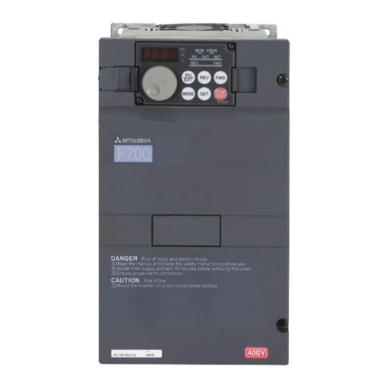
1 PRODUCT CHECKING AND PARTS IDENTIFICATION Unpack the inverter and check the capacity plate on the front cover and the rating plate on the inverter side face to ensure that the product agrees with your order and the inverter is intact. •... -
Page 9: Installation And Wiring
2 INSTALLATION AND WIRING Three-phase AC power supply Inverter Programmable controller Use within the permissible power supply (FR-F700) specifications of the inverter. (Refer to page 134) The life of the inverter is influenced by surrounding air temperature. The surrounding air temperature should be as low as possible within the permissible range. -
Page 10: Peripheral Devices
Peripheral devices 2.1 Peripheral devices Check the inverter model of the inverter you purchased. Appropriate peripheral devices must be selected according to the capacity. Refer to the following list and prepare appropriate peripheral devices: 200V class Input Side Magnetic Motor Breaker Selection Contactor Applicable Inverter Model... - Page 11 Peripheral devices 400V class Motor Input Side Magnetic Breaker Selection Output Contactor Applicable Inverter Model (kW) Without reactor With reactor Without reactor With reactor connection connection connection connection 0.75 FR-F740-0.75K 30AF 5A 30AF 5A S-N10 S-N10 FR-F740-1.5K 30AF 10A 30AF 10A S-N10 S-N10 FR-F740-2.2K...
-
Page 12: Method Of Removal And Reinstallation Of The
Method of removal and reinstallation of the front cover 2.2 Method of removal and reinstallation of the front cover •Removal of the operation panel 1) Loosen the two screws on the operation panel. 2) Push the left and right hooks of the operation panel (These screws cannot be removed.) and pull the operation panel toward you to remove. - Page 13 Method of removal and reinstallation of the front cover FR-F720-37K or more, FR-F740-37K or more • Removal 1) Remove installation screws on 2) Loosen the installation 3) Pull the front cover 2 toward you to the front cover 1 to remove the screws of the front cover 2.
-
Page 14: Installation Of The Inverter And Instructions
Installation of the inverter and instructions 2.3 Installation of the inverter and instructions • Installation of the Inverter Installation on the enclosure CAUTION 30K or less 37K or more ⋅ When encasing multiple inverters, install them in parallel as a cooling measure. ⋅... -
Page 15: Wiring
Wiring 2.4 Wiring 2.4.1 Terminal connection diagram Resistor unit *1. DC reactor (FR-HEL) *6. A CN8 (for MT-BU5) Sink logic Be sure to connect the DC reactor (Option) connector is provided supplied with the 75K or more. Brake unit Main circuit terminal When a DC reactor is connected with the 75K or more. -
Page 16: Emc Filter
Wiring 2.4.2 EMC filter This inverter is equipped with a built-in EMC filter (capacitive filter) and common mode choke. The EMC filter is effective for reduction of air-propagated noise on the input side of the inverter. The EMC filter is factory-set to disable (OFF). To enable it, fit the EMC filter ON/OFF connector to the ON position. The input side common mode choke, built-in the 55K or less inverter, is always valid regardless of ON/OFF of the EMC filter ON/OFF connector. -
Page 17: Specification Of Main Circuit Terminal
Wiring 2.4.3 Specification of main circuit terminal Terminal Terminal Name Description Symbol R/L1, Connect to the commercial power supply. S/L2, AC power input Keep these terminals open when using the high power factor converter T/L3 (FR-HC, MT-HC) or power regeneration common converter (FR-CV). U, V, W Inverter output Connect a three-phase squirrel-cage motor. - Page 18 Wiring FR-F720-7.5K, 11K FR-F720-15K R1/L11 S1/L21 Charge lamp Screw size (M4) Jumper Charge lamp P/+ PR Jumper Jumper Jumper R1/L11 S1/L21 Screw size (M5) Screw size (M5) R/L1 S/L2 T/L3 R/L1 S/L2 T/L3 Power supply Motor Power supply Motor Screw size (M5) * Screw size of terminal R1/L11, S1/L21, PR Screw size (M5)
- Page 19 Wiring 400V class FR-F740-0.75K to 5.5K FR-F740-7.5K, 11K Jumper Screw size (M4) R/L1 S/L2 T/L3 Charge lamp Jumper R1/L11 S1/L21 P/+ PR Jumper Jumper R1/L11 S1/L21 Screw size Charge lamp (M4) Screw size (M4) Power Motor supply R/L1 S/L2 T/L3 Power supply Motor Screw size...
- Page 20 Wiring FR-F740-132K to 220K FR-F740-250K to 560K R1/L11 S1/L21 R1/L11 S1/L21 Screw size (M4) Screw size (M4) Charge lamp Charge lamp Jumper Jumper Screw size (132K/160K: M10 185K/220K: M12) R/L1 S/L2 T/L3 N/- Screw size (M12) R/L1 S/L2 T/L3 N/- Screw size (M10) Power supply...
- Page 21 Wiring (1) Cable sizes etc., of the main control circuit terminals and earth (ground) terminals Select the recommended cable size to ensure that a voltage drop will be 2% max. If the wiring distance is long between the inverter and motor, a main circuit cable voltage drop will cause the motor torque to decrease especially at the output of a low frequency.
- Page 22 Wiring 400V class (when input power supply is 440V) Crimping Cable Sizes (Compression) Terminal Tightening AWG/MCM HIV, etc. (mm PVC, etc. (mm Applicable Terminal Screw Torque Inverter Type Earth Earth Size N·m R/L1, S/L2, R/L1, S/L2, R/L1, S/L2, R/L1, S/L2, U, V, W U, V, W U, V, W...
- Page 23 Wiring (2) Notes on earthing (grounding) • Leakage currents flow in the inverter. To prevent an electric shock, the inverter and motor must be earthed (grounded). This inverter must be earthed (grounded). Earthing (Grounding) must conform to the requirements of national and local safety regulations and electrical codes.
-
Page 24
Wiring (4) Cable size of the control circuit power supply (terminal R1/L11, S1/L21) · Terminal Screw Size: M4 · Cable size: 0.75mm to 2mm · Tightening torque: 1.5N·m (5) When connecting the control circuit and the main circuit separately to the power supply
... - Page 25 Wiring • FR-F720-15K, FR-F740-15K or more 1) Remove the upper screws. 2) Remove the lower screws. L21 Power supply 3) Pull the jumper toward you to terminal block remove. for the control circuit Power supply terminal block 4) Connect the separate power supply for the control circuit R/L1S/L2 T/L3 cable for the control circuit to the...
-
Page 26: Control Circuit Terminals
Wiring 2.4.5 Control circuit terminals indicates that terminal functions can be selected using Pr. 178 to Pr. 196 (I/O terminal function selection) (Refer to the chapter 4 of the Instruction Manual (applied).) (1) Input signals Terminal Terminal Rated Description Refer to Symbol Name Specifications... - Page 27 Wiring Terminal Terminal Rated Description Refer to Symbol Name Specifications 10VDC When connecting the frequency setting potentiometer at an initial Permissible load status, connect it to terminal 10. Frequency current 10mA Change the input specifications of terminal 2 when connecting it setting power 5VDC to terminal 10E.
- Page 28 Wiring (2) Output signals Terminal Terminal Rated Description Refer to Symbol Name Specifications 1 changeover contact output indicates that the inverter Relay output 1 protective function has activated and the output stopped. Contact capacity: (Fault output) Fault: No conduction across B-C (Across A-C Continuity), 230VAC 0.3A Normal: Across B-C Continuity (No conduction across A-C) (Power...
-
Page 29: Changing The Control Logic
Wiring 2.4.6 Changing the control logic The input signals are set to sink logic (SINK) when shipped from the factory. To change the control logic, the jumper connector on the back of the control circuit terminal block must be moved to the other position. - Page 30 Wiring 4) Sink logic and source logic ⋅ In sink logic, a signal switches on when a current flows from the corresponding signal input terminal. Terminal SD is common to the contact input signals. Terminal SE is common to the open collector output signals. ⋅...
-
Page 31: Wiring Of Control Circuit
Wiring 2.4.7 Wiring of control circuit (1) Control circuit terminal layout Control circuit terminal C2 10E 10 Terminal screw size: M3.5 Tightening torque: 1.2N.m STOP (2) Common terminals of the control circuit (SD 5, SE) Terminals SD, 5, and SE are all common terminals (0V) for I/O signals and are isolated from each other. Do not earth(ground) these terminals. - Page 32 Wiring (4) Wiring instructions It is recommended to use the cables of 0.75mm gauge for connection to the control circuit terminals. If the cable gauge used is 1.25mm or more, the front cover may be lifted when there are many cables running or the cables are run improperly, resulting in an operation panel contact fault.
-
Page 33: When Connecting The Operation Panel Using A Connection Cable
Wiring 2.4.8 When connecting the operation panel using a connection cable Having an operation panel on the enclosure surface is convenient. With a connection cable, you can mount the operation panel (FR-DU07) to the enclosure surface, and connect it to the inverter. Parameter unit connection cable (FR-CB2 )(option) -
Page 34: Terminal Block
Wiring 2.4.9 RS-485 terminal block ⋅ Conforming standard: EIA-485(RS-485) ⋅ Transmission format: Multidrop link OPEN ⋅ Communication speed: MAX 38400bps ⋅ Overall length: 500m Terminating resistor switch ⋅ Connection cable:Twisted pair cable Factory-set to "OPEN". (4 pairs) Set only the terminating resistor switch of the remotest inverter to the "100Ω"... -
Page 35: Connection Of Stand-Alone Option Units
Connection of stand-alone option units 2.5 Connection of stand-alone option units The inverter accepts a variety of stand-alone option units as required. Incorrect connection will cause inverter damage or accident. Connect and operate the option unit carefully in accordance with the corresponding option unit manual. 2.5.1 Connection of the brake unit (FR-BU2) Connect the brake unit (FR-BU2) as shown below to improve the braking capability at deceleration. - Page 36 Connection of stand-alone option units (2) FR-BR-(H) connection example with resistor unit FR-BR MCCB Motor R/L1 Three phase AC S/L2 power supply T/L3 FR-BU2 Inverter 5m or less Connect the inverter terminals (P/+, N/-) and brake unit (FR-BU2) terminals so that their terminal names match with each other. (Incorrect connection will damage the inverter and brake unit.) When the power supply is 400V class, install a step-down transformer.
-
Page 37: Connection Of The Brake Unit (Fr-Bu/Mt-Bu5)
Connection of stand-alone option units 2.5.2 Connection of the brake unit (FR-BU/MT-BU5) When connecting the brake unit (FR-BU(H)/MT-BU5) to improve the brake capability at deceleration, make connection as shown below. (1) Connection with the FR-BU (55K or less) FR-BR MCCB Motor R/L1 Three-phase AC... - Page 38 Connection of stand-alone option units (2) Connection with the MT-BU5 (75K or more) After making sure that the wiring is correct, set "1" in Pr.30 Regenerative function selection. (Refer to the chapter 4 of the Instruction Manual (applied).) MCCB Motor R/L1 Three-phase AC power...
-
Page 39: Connection Of The Brake Unit (Bu Type)
Connection of stand-alone option units 2.5.3 Connection of the brake unit (BU type) Connect the brake unit (BU type) correctly as shown below. Incorrect connection will damage the inverter. Remove the jumper across terminals HB-PC and terminals TB-HC of the brake unit and fit it to across terminals PC-TB. Inverter MCCB Motor... - Page 40 Connection of stand-alone option units (2) Connection with the MT-HC (75K or more) MT-HCL01 MT-HCB MT-HCL02 MT-HC Inverter MCCB Motor Three-phase R/L1 AC power S/L2 supply T/L3 R1 S1 MT-HCTR Isolated transformer Remove the jumper across terminals R-R1, S-S1 of the inverter, and connect the control circuit power supply to the R1 and S1 terminals.
-
Page 41: Connection Of The Power Regeneration Common Converter (Fr-Cv)(55K Or Less)
Connection of stand-alone option units 2.5.5 Connection of the power regeneration common converter (FR-CV)(55K or less) When connecting the power regeneration common converter (FR-CV), make connection so that the inverter terminals (P/+, N/-) and the terminal symbols of the power regeneration common converter (FR-CV) are the same. After making sure that the wiring is correct, set "2"... -
Page 42: Connection Of The Power Regeneration Converter (Mt-Rc) (75K Or More)
Ready signal MT-RC CAUTION ⋅ When using the FR-F700 series together with the MT- Inverter input power supply (MC2) RC, install a magnetic contactor (MC) at the input side of the inverter so that power is supplied to the inverter after 1s or more has elapsed after powering on the MT-RC. -
Page 43: Power-Off And Magnetic Contactor (Mc)
Power-off and magnetic contactor (MC) 2.6 Power-off and magnetic contactor (MC) (1) Inverter input side magnetic contactor (MC) On the inverter input side, it is recommended to provide an MC for the following purposes. page for selection.) Refer to 1) To release the inverter from the power supply when the fault occurs or when the drive is not functioning (e.g. emergency stop operation). -
Page 44: Precautions For Use Of The Inverter
Precautions for use of the inverter 2.7 Precautions for use of the inverter The FR-F700 series is a highly reliable product, but incorrect peripheral circuit making or operation/handling method may shorten the product life or damage the product. Before starting operation, always recheck the following items. - Page 45 Precautions for use of the inverter (13) If the machine must not be restarted when power is restored after a power failure, provide a magnetic contactor in the inverter's input side and also make up a sequence which will not switch on the start signal. If the start signal (start switch) remains on after a power failure, the inverter will automatically restart as soon as the power is restored.
-
Page 46: Failsafe Of The System Which Uses The Inverter
Failsafe of the system which uses the inverter 2.8 Failsafe of the system which uses the inverter When a fault occurs, the inverter trips to output a fault signal. However, a fault output signal may not be output at an inverter fault occurrence when the detection circuit or output circuit fails, etc. -
Page 47: Drive The Motor
Step of operation 3 DRIVE THE MOTOR 3.1 Step of operation The inverter needs frequency command and start command. Frequency command (set frequency) determines the rotation speed of the motor. Turning ON the start command starts the motor to rotate. Refer to the flow chart below to perform setting. -
Page 48: Operation Panel (Fr-Du07)
Operation panel (FR-DU07) 3.2 Operation panel (FR-DU07) 3.2.1 Parts of the operation panel (FR-DU07) Operation mode indication PU: Lit to indicate PU operation mode. EXT: Lit to indicate External operation mode. NET: Lit to indicate Network operation mode. Rotation direction indication FWD: Lit during forward rotation REV: Lit during reverse rotation Forward/reverse operation... -
Page 49: Basic Operation (Factory Setting)
Operation panel (FR-DU07) 3.2.2 Basic operation (factory setting) Operation mode switchover At powering on (External operation mode) PU Jog operation mode (Refer to page 45) (Example) Value change and frequency flicker. PU operation mode Frequency setting has been (output frequency monitor) written and completed!! Output current monitor Output voltage monitor... -
Page 50: Operation Lock (Press [Mode] For An Extended Time (2S))
Operation panel (FR-DU07) 3.2.3 Operation lock (Press [MODE] for an extended time (2s)) Operation using the setting dial and key of the operation panel can be invalid to prevent parameter change, and unexpected start or frequency setting. · Set "10 or 11" in Pr. 161, then press for 2s to make the setting dial and key operation invalid. -
Page 51: Monitoring Of Output Current And Output Voltage
Operation panel (FR-DU07) 3.2.4 Monitoring of output current and output voltage POINT Monitor display of output frequency, output current and output voltage can be changed by pushing during monitoring mode. Operation Display Press during operation to choose the output frequency monitor Independently of whether the inverter is running in any operation mode or at a stop, the output current monitor appears by pressing... -
Page 52: Changing The Parameter Setting Value
Operation panel (FR-DU07) 3.2.7 Changing the parameter setting value Changing example Change the Pr. 1 Maximum frequency . Operation Display Screen at powering on The monitor display appears. PU indication is lit. Press to choose the PU operation mode. The parameter Press to choose the parameter number read... -
Page 53: Overheat Protection Of The Motor By The Inverter (Pr. 9)
Overheat protection of the motor by the inverter (Pr. 9) 3.3 Overheat protection of the motor by the inverter (Pr. 9) Set the rated motor current in Pr. 9 Electronic thermal O/L relay to protect the motor from overheat. Parameter Name Initial Value Setting Range... -
Page 54: When The Rated Motor Frequency Is 50Hz (Pr. 3)
When the rated motor frequency is 50Hz (Pr. 3) 3.4 When the rated motor frequency is 50Hz (Pr. 3) First, check the motor rating plate. If a frequency given on the rating plate is "50Hz" only, always set Pr. 3 Base frequency to "50Hz". -
Page 55: Start/Stop From The Operation Panel (Pu Operation Mode)
Start/stop from the operation panel (PU operation mode) 3.5 Start/stop from the operation panel (PU operation mode) POINT From where is the frequency command given? · Operation at the frequency set in the frequency setting mode of the operation panel →Refer to 3.5.1 (Refer to page 48) ·... -
Page 56: Operation Mode
Start/stop from the operation panel (PU operation mode) Operation cannot be performed at the set frequency ... Why? Did you carry out step 4 within 5s after step 3? (Did you press within 5s after turning The frequency does not change by turning ... -
Page 57: Using The Setting Dial Like A Potentiometer At The Operation
Start/stop from the operation panel (PU operation mode) 3.5.2 Using the setting dial like a potentiometer at the operation. POINT Set "0" (extended mode parameter valid) in Pr. 160 User group read selection. Set "1" (setting dial potentiometer mode) in Pr. 161 Frequency setting/key lock operation selection. Operation example Change the frequency from 0Hz to 60Hz during operation Operation Display... -
Page 58: Setting The Frequency By Switches (Three-Speed Setting)
Start/stop from the operation panel (PU operation mode) 3.5.3 Setting the frequency by switches (three-speed setting) POINT · To give a start command, of the operation panel (FR-DU07) is used. · To give a frequency command, terminal between SD and terminal RH, RM, or RL is turned ON. (three-speed setting) ·... -
Page 59: Operation Display
Start/stop from the operation panel (PU operation mode) Operation Display Acceleration constant speed Press to start running. The frequency on the indication increases by the Pr.7 Acceleration time, and " " (10.00Hz) appears. Deceleration Press to stop. Stop The frequency on the indication decreases by the Pr. -
Page 60: Setting The Frequency By Analog Input (Voltage Input)
Start/stop from the operation panel (PU operation mode) 3.5.4 Setting the frequency by analog input (voltage input) POINT · To give a start command, of the operation panel (FR-DU07) is used . · Frequency command is given from the potentiometer. (by connecting terminal 2 and 5.) ·... - Page 61 Start/stop from the operation panel (PU operation mode) Operation Display Deceleration Turn the potentiometer (frequency setting potentiometer) counterclockwise slowly to full. Flickering The frequency on the indication decreases Stop by the Pr. 8 Deceleration time, and the motor stops rotating with " "...
-
Page 62: Setting The Frequency By Analog Input (Current Input)
Start/stop from the operation panel (PU operation mode) 3.5.5 Setting the frequency by analog input (current input) POINT · To give a start command, of the operation panel (FR-DU07) is used. · Frequency command is given from the current signal source (4 to 20mA). (by connecting terminal 4 and 5.) ·... - Page 63 Start/stop from the operation panel (PU operation mode) Operation Display Acceleration → constant speed Current signal Perform 20mA input. source The frequency on the indication increases by (20mADC) the Pr. 7 Acceleration time and " " (60.00Hz) appears. Deceleration Current signal Input 4mA or less.
-
Page 64: Start And Stop Using Terminals (External Operation)
Start and stop using terminals (External operation) 3.6 Start and stop using terminals (External operation) POINT From where is the frequency command given? · Operation at the frequency set in the frequency setting mode of the operation panel → Refer to 3.6.1(Refer to page 57) ·... - Page 65 Start and stop using terminals (External operation) Operation Display Turn to show the selected Flickers for about 5s frequency, " " (30.00Hz). The frequency flickers for about 5s. While the value is flickering, press to set the frequency. Flicker ··· Frequency setting complete!! If you do not press ,the value flickers for about 5s and the display then returns...
-
Page 66: Setting The Frequency By Switches (Three-Speed Setting) (Pr. 4 To Pr. 6)
Start and stop using terminals (External operation) 3.6.2 Setting the frequency by switches (three-speed setting) (Pr. 4 to Pr. 6) POINT · Start command by terminal STF (STR) · Frequency command by terminal RH, RM, RL and STR · [EXT] must be lit. (When [PU] is lit, switch it to [EXT] with ·... - Page 67 Start and stop using terminals (External operation) [EXT] is not lit even when is pressed ... Why? Switchover of the operation mode with is valid when Pr. 79 = "0" (initial value). 60Hz, 30Hz and 10Hz are not output from RH, RM and RL respectively when they are turned on..Why? Check for the setting of Pr.
-
Page 68: Setting The Frequency By Analog Input (Voltage Input)
Start and stop using terminals (External operation) 3.6.3 Setting the frequency by analog input (voltage input) POINT · To give a start command, terminal between SD and STF (STR) is turned ON. · Frequency command is given from the potentiometer (by connecting terminal 2 and 5). [Connection diagram] (The inverter supplies 5V of power to frequency setting potentiometer. -
Page 69: Changing The Output Frequency (60Hz, Initial Value) At The Maximum Voltage Input (5V, Initial Value)
Start and stop using terminals (External operation) REMARKS Pr. 178 STF terminal function selection must be set to "60" (or Pr. 179 STR terminal function selection must be set to "61"). (all are initial values) The motor will not rotate ... Why? Check that [EXT] is lit. -
Page 70: Setting The Frequency By Analog Input (Current Input)
Start and stop using terminals (External operation) 3.6.5 Setting the frequency by analog input (current input) POINT · Switch terminal STF(STR)-SD on to give a start command. · Turn the AU signal on. · Set "2" (External operation mode) in Pr. 79 Operation mode selection [Connection diagram] Inverter Forward rotation start... -
Page 71: Changing The Output Frequency (60Hz, Initial Value) At The Maximum Current Input (At 20Ma, Initial Value)
Start and stop using terminals (External operation) The motor will not rotate ... Why? Check that [EXT] is lit. [EXT] is valid when Pr. 79 = "0" (initial value). to lit [EXT]. Check that the AU signal is on. Turn the AU signal on. Check that wiring is correct. -
Page 72: Adjustment
Simple mode parameter list 4 ADJUSTMENT 4.1 Simple mode parameter list For simple variable-speed operation of the inverter, the initial setting of the parameters may be used as they are. Set the necessary parameters to meet the load and operational specifications. Parameter setting, change and check can be made from the operation panel (FR-DU07). -
Page 73: Increasing The Starting Torque (Pr. 0)
Increasing the starting torque (Pr. 0) 4.2 Increasing the starting torque (Pr. 0) Set this parameter when "the motor with a load will not rotate", "an alarm [OL] is output, resulting in an inverter trip due to [OC1], etc. Parameter Setting Name Initial Value... -
Page 74: Limiting The Maximum And Minimum Output Frequency (Pr. 1, Pr. 2)
Limiting the maximum and minimum output frequency (Pr. 1, Pr. 2) Limiting the maximum and minimum output frequency (Pr. 1, Pr. 2) Parameter Setting Name Initial Value Description Number Range 120Hz 55K or less Set the upper limit of the output Maximum frequency 0 to 120Hz frequency. -
Page 75: Changing Acceleration And Deceleration Time (Pr. 7, Pr. 8)
Changing acceleration and deceleration time (Pr. 7, Pr. 8) 4.4 Changing acceleration and deceleration time (Pr. 7, Pr. 8) Set in Pr. 7 Acceleration time a larger value for a slower speed increase and a smaller value for a faster speed increase. Set in Pr. -
Page 76: Energy Saving Operation (Pr. 60)
Energy saving operation (Pr. 60) 4.5 Energy saving operation (Pr. 60) Without a fine parameter setting, the inverter automatically performs energy saving operation. This inverter is appropriate for fan and pump applications Parameter Initial Setting Name Remarks Number Value Range Normal operation mode Energy saving control selection Energy saving operation mode... - Page 77 Energy saving operation (Pr. 60) Operation Display Screen at powering on The monitor display appears. PU indication is lit. Press to choose the PU operation mode. The parameter Press to choose the parameter number previously setting mode. read appears. Turn until (Pr.
-
Page 78: Selection Of The Operation Command And Frequency Command Locations (Pr. 79)
Selection of the operation command and frequency command locations (Pr. 79) 4.6 Selection of the operation command and frequency command locations (Pr. 79) Select the start command location and frequency command location. LED Indication Parameter Initial Setting Name Description : Off Number Value Range... -
Page 79: Parameter Clear, All Parameter Clear
Parameter clear, all parameter clear 4.7 Parameter clear, all parameter clear POINT · Set "1" in Pr. CL parameter clear, ALLC All parameter clear to initialize parameters. (Parameters are not cleared when "1" is set in Pr. 77 Parameter write selection.) ·... -
Page 80: Parameter Copy And Parameter Verification
Verify parameters in the inverter and operation panel. (Refer to page 74.) REMARKS · When the copy destination inverter is not the FR-F700 series or parameter copy write is performed after parameter copy read is stopped, "model error ( )" is displayed. -
Page 81: Parameter Verification
If there is no difference, flicker to complete verification. Flicker ··· Parameter verification complete!! REMARKS When the copy destination inverter is not the FR-F700 series, "model error ( )" is displayed. flickers ... Why? Set frequencies, etc. may be different. Check set frequencies. -
Page 82: Parameter List
Parameter list 4.9 Parameter list 4.9.1 List of parameters classified by the purpose Set the parameters according to the operating conditions. The following list indicates purpose of use and corresponding parameters. Purpose of Use Parameter Number Manual torque boost Pr. 0, Pr. 46 Simple magnetic flux vector control Pr. - Page 83 Parameter list Purpose of Use Parameter Number Restart operation after instantaneous power failure/Flying Pr. 57, Pr. 58, Pr. 162 to Pr. 165, Pr. Operation selection at power start 299, Pr. 611 failure and instantaneous power failure Decelerate the motor to a stop at instantaneous power failure Pr. 261 to Pr. 266 Retry function at fault occurrence Pr.
-
Page 84: Display Of The Extended Parameters
Parameter list 4.9.2 Display of the extended parameters Operation Display Screen at powering on The monitor display appears. PU indication is lit. Press to choose the PU operation mode. The parameter Press to choose the parameter number read previously appears. setting mode. -
Page 85: Parameter List
Parameter list 4.9.3 Parameter list indicates simple mode parameters. Parameter Para Para para meter meter meter Incre Initial copy clear Name Range Description clear ments Value : enabled × : disabled Set the output voltage at 0Hz as %. Initial values differ according to the 6/4/3/2/ inverter capacity. - Page 86 Parameter list Parameter Para Para para meter meter meter Incre Initial copy clear Name Range Description clear ments Value : enabled × : disabled Set the motor acceleration time. 0.1/ 0 to 3600/ Acceleration time 5/15s Initial values differ according to the inverter 0.01s 360s capacity.
- Page 87 Parameter list Parameter Para Para para meter meter meter Incre Initial copy clear Name Range Description clear ments Value : enabled × : disabled Jog frequency 0.01Hz 0 to 400Hz Set the frequency for jog operation. Set the acceleration/deceleration time for jog operation.
- Page 88 Parameter list Parameter Para Para para meter meter meter Incre Initial copy clear Name Range Description clear ments Value : enabled × : disabled Without compensation Multi-speed input compensation selection With compensation Linear acceleration/ deceleration S-pattern acceleration/deceleration A Acceleration/ deceleration pattern S-pattern acceleration/deceleration B selection Backlash measures...
- Page 89 Parameter list Parameter Para Para para meter meter meter Incre Initial copy clear Name Range Description clear ments Value : enabled × : disabled 0 to 400Hz, Frequency jump 1A 0.01Hz 9999 9999 0 to 400Hz, Frequency jump 1B 0.01Hz 9999 9999 0 to 400Hz,...
- Page 90 Parameter list Parameter Para Para para meter meter meter Incre Initial copy clear Name Range Description clear ments Value : enabled × : disabled 1 to 3, 5, 6, 8 Select the monitor output to terminal FM. FM terminal to 14, 17, 21, The setting value of "9"...
- Page 91 Parameter list Parameter Para Para para meter meter meter Incre Initial copy clear Name Range Description clear ments Value : enabled × : disabled RH, RM, RL signal Frequency setting function storage function ⎯ Multi-speed setting Used Not used No (Turning STF/ Remote setting STR off clears Remote function...
- Page 92 Parameter list Parameter Para Para para meter meter meter Incre Initial copy clear Name Range Description clear ments Value : enabled × : disabled You can select the input specifications of terminal 2 (0 to 5V, 0 to 10V, 0 to 20mA) and input specifications of terminal 1 (0 to ±5V, 0 to ±10V).
- Page 93 Parameter list Parameter Para Para para meter meter meter Incre Initial copy clear Name Range Description clear ments Value : enabled × : disabled External/PU switchover mode Fixed to PU operation mode Fixed to External operation mode Operation mode External/PU combined operation mode 1 selection External/PU combined operation mode 2 Switchover mode...
- Page 94 Parameter list Parameter Para Para para meter meter meter Incre Initial copy clear Name Range Description clear ments Value : enabled × : disabled Specify the inverter station number. PU communication Set the inverter station numbers when two 0 to 31 or more inverters are connected to one station number personal computer.
- Page 95 Parameter list Parameter Para Para para meter meter meter Incre Initial copy clear Name Range Description clear ments Value : enabled × : disabled Terminal 2 Set the frequency of terminal 2 input gain × frequency setting 0.01Hz 60Hz 0 to 400Hz (maximum).
- Page 96 Parameter list Parameter Para Para para meter meter meter Incre Initial copy clear Name Range Description clear ments Value : enabled × : disabled PID control Set the frequency at which the control is 0 to 400Hz automatically changed to PID control. automatic 0.01Hz 9999...
- Page 97 Parameter list Parameter Para Para para meter meter meter Incre Initial copy clear Name Range Description clear ments Value : enabled × : disabled For deviation lamp input, time (Td) required for providing only the manipulated variable 0.01 to for the proportional (P) action. As the 10.00s PID differential time 0.01s...
- Page 98 Parameter list Parameter Para Para para meter meter meter Incre Initial copy clear Name Range Description clear ments Value : enabled × : disabled Electronic bypass Without electronic bypass sequence sequence selection With electronic bypass sequence MC switchover Set the operation interlock time of MC2 and 0.1s 0 to 100s interlock time...
- Page 99 Parameter list Parameter Para Para para meter meter meter Incre Initial copy clear Name Range Description clear ments Value : enabled × : disabled Output current Set the output current detection level. 0.1% 120% 0 to 150% detection level 100% is the rated inverter current. Set the output current detection period.
- Page 100 Parameter list Parameter Para Para para meter meter meter Incre Initial copy clear Name Range Description clear ments Value : enabled × : disabled 162 to 165 Refer to Pr.57 and Pr.58. 166, 167 Refer to Pr.150 to Pr.153. 168, 169 Parameter for manufacturer setting.
- Page 101 Parameter list Parameter Para Para para meter meter meter Incre Initial copy clear Name Range Description clear ments Value : enabled × : disabled 0, 100: Inverter running (RUN) 1, 101: Up to frequency (SU) RUN terminal 2, 102: Instantaneous power failure/ ×...
- Page 102 Parameter list Parameter Para Para para meter meter meter Incre Initial copy clear Name Range Description clear ments Value : enabled × : disabled Operates at power on Cooling fan on/off control invalid (The cooling fan is always on at power on) Cooling fan Cooling fan on/off control valid operation selection...
- Page 103 Parameter list Parameter Para Para para meter meter meter Incre Initial copy clear Name Range Description clear ments Value : enabled × : disabled Displays whether the control circuit capacitor, Life alarm status main circuit capacitor, cooling fan, and each ×...
- Page 104 Parameter list Parameter Para Para para meter meter meter Incre Initial copy clear Name Range Description clear ments Value : enabled × : disabled Set the inverter station number. RS-485 0 to 31 (same specifications as Pr.117 ) When "1" communication (Modbus-RTU protocol) is set in Pr.551, the (0 to 247)
- Page 105 Parameter list Parameter Para Para para meter meter meter Incre Initial copy clear Name Range Description clear ments Value : enabled × : disabled Refer to Pr.79. — Remote output data clear at powering off Remote output data clear at inverter reset Remote output data Remote output held at powering off...
- Page 106 Parameter list Parameter Para Para para meter meter meter Incre Initial copy clear Name Range Description clear ments Value : enabled × : disabled Regeneration avoidance function invalid Regeneration Regeneration avoidance function is always avoidance valid operation selection Regeneration avoidance function is valid only during a constant speed operation Set the bus voltage level at which regeneration avoidance operates.
- Page 107 Parameter list Parameter Para Para para meter meter meter Incre Initial copy clear Name Range Description clear ments Value : enabled × : disabled Refer to Pr.52. Set the load factor for commercial power- supply operation. Load factor 0.1% 100% 30 to 150% This value is used to calculate the power consumption estimated value during...
- Page 108 Parameter list Parameter Para Para para meter meter meter Incre Initial copy clear Name Range Description clear ments Value : enabled × : disabled Contrast adjustment of the LCD of the PU contrast parameter unit (FR-PU04/FR-PU07) can be 0 to 63 adjustment performed.
-
Page 109: Troubleshooting
Reset method of protective function 5 TROUBLESHOOTING When a fault occurs in the inverter, the inverter trips and the PU display automatically changes to any of the following fault or alarm indications. If the fault does not correspond to any of the following faults or if you have any other problem, please contact your sales representative or distributor. -
Page 110: List Of Fault Or Alarm Display
List of fault or alarm display 5.2 List of fault or alarm display Operation Panel Refer Operation Panel Refer Name Name Indication Indication Output side earth (ground) E.GF E--- Faults history fault overcurrent HOLD Operation panel lock E.LF Output phase loss External thermal relay E.OHT Er1 to 4 Parameter write error... -
Page 111: Causes And Corrective Actions
Causes and corrective actions 5.3 Causes and corrective actions (1) Error Message A message regarding operational troubles is displayed. Output is not shut off. Operation Panel HOLD Indication Name Operation panel lock Description Operation lock mode is set. Operation other than is invalid. - Page 112 2. Check that the power is not turned off or an operation panel is not disconnected, etc. during parameter copy read. 1. Use the same model (FR-F700 series) for parameter copy and verification. Corrective action 2. Perform parameter copy read again.
- Page 113 Causes and corrective actions (2) Warnings When the protective function is activated, the output is not shut off. Operation Panel FR-PU04 Indication FR-PU07 Name Stall prevention (overcurrent) When the output current of the inverter exceeds the stall prevention operation level (Pr. 22 Stall prevention operation level, etc.), this function stops the increase in frequency until During the overload current decreases to prevent the inverter from resulting in overcurrent trip.
- Page 114 Causes and corrective actions Operation Panel FR-PU04 Indication FR-PU07 Name Regenerative brake prealarm Appears if the regenerative brake duty reaches or exceeds 85% of the Pr. 70 Special regenerative brake duty value. When the setting of Pr. 70 Special regenerative brake duty is the initial value (Pr. 70 ="0"), this warning does not occur.
- Page 115 Causes and corrective actions (4) Fault When a fault occurs, the inverter trips and a fault signal is output. Operation Panel FR-PU04 E.OC1 OC During Acc Indication FR-PU07 Name Overcurrent trip during acceleration When the inverter output current reaches or exceeds approximately 170% of the rated current during Description acceleration, the protective circuit is activated to stop the inverter output.
- Page 116 Causes and corrective actions Operation Panel FR-PU04 E.OV1 OV During Acc Indication FR-PU07 Name Regenerative overvoltage trip during acceleration If regenerative energy causes the inverter's internal main circuit DC voltage to reach or exceed the Description specified value, the protective circuit is activated to stop the inverter output. The circuit may also be activated by a surge voltage produced in the power supply system.
- Page 117 Causes and corrective actions Operation Panel FR-PU04 E.THM Motor Ovrload Indication FR-PU07 Name Motor overload trip (electronic thermal relay function) The electronic thermal relay function in the inverter detects motor overheat due to overload or reduced cooling capability during constant-speed operation and pre-alarm (TH display) is output when the integrated value reaches 85% of the Pr.
- Page 118 Causes and corrective actions FR-PU04 Operation Panel E.UVT Under Voltage Indication FR-PU07 Name Undervoltage If the power supply voltage of the inverter decreases, the control circuit will not perform normal functions. In addition, the motor torque will be insufficient and/or heat generation will increase. To prevent this, if the power supply voltage decreases below about 150V (300VAC for the 400V class), this function stops the inverter output.
- Page 119 Causes and corrective actions FR-PU04 Fault 14 Operation Panel E.PTC Indication FR-PU07 PTC activated Name PTC thermistor operation Trips when the motor overheat status is detected for 10s or more by the external PTC thermistor input connected to the terminal AU. Description This fault functions when "63"...
- Page 120 Causes and corrective actions FR-PU04 Fault 14 Operation Panel E.PE2 Indication FR-PU07 PR storage alarm Name Parameter storage device fault (main circuit board) Description Trips when a fault occurred in the parameter stored. (EEPROM failure) Check point —————— Corrective action Please contact your sales representative.
- Page 121 Causes and corrective actions Operation Panel FR-PU04 E.P24 E.P24 Indication FR-PU07 Name 24VDC power output short circuit When the 24VDC power output from the PC terminal is shorted, this function shuts off the power output. Description At this time, all external contact inputs switch off. The inverter cannot be reset by entering the RES signal.
-
Page 122: Correspondences Between Digital And Actual Characters
Correspondences between digital and actual characters Operation Panel FR-PU04 E.13 Fault 13 Indication FR-PU07 Name Internal circuit fault Description Trips when an internal circuit error occurred. Corrective action Please contact your sales representative. CAUTION • If protective functions of E.ILF, E.PTC, E.PE2, E.CDO, E.IOH, E.SER, E.AIE, E.PID are activated when using the FR-PU04, "Fault 14"... -
Page 123: Check And Clear Of The Faults History
Check and clear of the faults history 5.5 Check and clear of the faults history (1) Check for the faults history Monitor/frequency setting Parameter setting [Operation panel is used [Parameter setting change] for operation] Faults history [Operation for displaying faults history] Eight past faults can be displayed with the setting dial. - Page 124 Check and clear of the faults history (2) Clearing procedure POINT · The faults history can be cleared by setting "1" in Er.CL Faults history clear. Display Operation Screen at powering on The monitor display appears. The parameter Press to choose the parameter number previously setting mode.
-
Page 125: Check First When You Have A Trouble
Check first when you have a trouble Check first when you have a trouble 5.6.1 Motor does not start Refer Check Possible Cause Countermeasures points page Power ON a moulded case circuit breaker (MCCB), an earth leakage circuit breaker (ELB), or a magnetic contactor (MC). - Page 126 Check first when you have a trouble Refer Check Possible Cause Countermeasures points page Increase Pr. 0 setting by 0.5% increments while Pr. 0 Torque boost setting is improper when V/F control is observing the rotation of a motor. used. If that makes no difference, decrease the setting.
-
Page 127: Motor Or Machine Is Making Abnormal Acoustic Noise
Check first when you have a trouble 5.6.2 Motor or machine is making abnormal acoustic noise When operating the inverter with the carrier frequency of 3kHz or more set in Pr. 72, the carrier frequency will automatically decrease if the output current of the inverter exceeds the value in parenthesis of the rated output current on page 134. This may cause the motor noise to increase. -
Page 128: Motor Rotates In The Opposite Direction
Check first when you have a trouble 5.6.5 Motor rotates in the opposite direction Refer Check Possible Cause Countermeasures points page Main Phase sequence of output terminals U, V and W is Connect phase sequence of the output cables (terminal Circuit incorrect. -
Page 129: Speed Varies During Operation
Check first when you have a trouble 5.6.8 Speed varies during operation Refer Check Possible Cause Countermeasures points page Load Load varies during an operation. Select Simple magnetic flux vector control Frequency setting signal is varying. Check the frequency setting signal. —... -
Page 130: Operation Panel (Fr-Du07) Display Is Not Operating
Check first when you have a trouble 5.6.10 Operation panel (FR-DU07) display is not operating Refer Check Possible Cause Countermeasures points page Main Circuit, Power is not input. Input the power. Control Circuit Check if the inverter front cover is installed securely. The inverter cover may not fit properly when using wires Front Operation panel is not properly connected to the... -
Page 131: Speed Does Not Accelerate
Check first when you have a trouble 5.6.12 Speed does not accelerate Refer Check Possible Cause Countermeasures points page Check if the start command and the frequency Start command and frequency command are chattering. — command are correct. Input The wiring length used for analog frequency command Perform analog input bias/gain calibration. -
Page 132: Precautions For Maintenance And Inspection
Inspection item 6 PRECAUTIONS FOR MAINTENANCE AND INSPECTION The inverter is a static unit mainly consisting of semiconductor devices. Daily inspection must be performed to prevent any fault from occurring due to the adverse effects of the operating environment, such as temperature, humidity, dust, dirt and vibration, changes in the parts with time, service life, and other factors. -
Page 133: Daily And Periodic Inspection
Inspection item 6.1.3 Daily and periodic inspection Interval Corrective Action at Inspection Item Inspection Item Alarm Occurrence Check the surrounding air temperature, humidity, Surrounding Improve environment environment dirt, corrosive gas, oil mist , etc Check alarm location and General Overall unit Check for unusual vibration and noise retighten Power supply... -
Page 134: Display Of The Life Of The Inverter Parts
Inspection item 6.1.4 Display of the life of the inverter parts The self-diagnostic alarm is output when the life span of the control circuit capacitor, cooling fan, each parts of the inrush current limit circuit is near its end. It gives an indication of replacement time . The life alarm output can be used as a guideline for life judgement. - Page 135 Inspection item (2) Measuring method of life of the main circuit capacitor · If the value of capacitor capacity measured before shipment is considered as 100%, Pr. 255 bit1 is turned on when the measured value falls below 85%. · Measure the capacitor capacity according to the following procedure and check the deterioration level of the capacitor capacity.
-
Page 136: Cleaning
Inspection item 6.1.5 Cleaning Always run the inverter in a clean status. When cleaning the inverter, gently wipe dirty areas with a soft cloth immersed in neutral detergent or ethanol. CAUTION Do not use solvent, such as acetone, benzene, toluene and alcohol, as they will cause the inverter surface paint to peel off. The display, etc. - Page 137 Inspection item (1) Cooling fan The replacement interval of the cooling fan used for cooling the parts generating heat such as the main circuit semiconductor is greatly affected by the surrounding air temperature. When unusual noise and/or vibration is noticed during inspection, the cooling fan must be replaced immediately. CAUTION For parts replacement, consult the nearest Mitsubishi FA Center.
-
Page 138
Inspection item • Reinstallation (FR-F720-2.2K to 110K, FR-F740-3.7K to 160K) 1)After confirming the orientation of the fan, reinstall the fan so that the arrow on the left of "AIR FLOW" faces up. AIR FLOW
2)Reconnect the fan connectors. FR-F720-7.5K to 15K FR-F720-2.2K to 5.5K FR-F740-7.5K to 18.5K... - Page 139 Inspection item • Removal (FR-F740-185K or more) 1) Remove a fan cover. 2) After removing a fan connector, remove a fan block. 3) Remove a fan. Fan * Fan connection connector * The number of cooling fans differs according to the inverter capacity. •...
-
Page 140: Inverter Replacement
Inspection item (2) Replacement procedure of the cooling fan when using a heatsink protrusion attachment (FR-A7CN) When replacing a cooling fan, remove a top cover of the heatsink protrusion attachment and perform replacement. After replacing the cooling fan, replace the top cover in the original position. -
Page 141: Specifications
Rating 7 SPECIFICATIONS 7.1 Rating •200V class Type FR-F720- 0.75 18.5 Applicable motor capacity 0.75 1.5 18.5 (kW) Rated capacity (kVA) 11.8 17.1 22.1 132 165 15.2 Rated current (A) (3.6) (6.0) (8.2) (13) (20) (26) (38) (49) (60) (72) (97) (119) (145) - Page 142 Rating •400V class Type FR-F740- 0.75 18.5 0.75 18.5 Applicable motor capacity (kW) 12.2 17.5 22.1 26.7 32.8 43.4 53.3 64.8 80.8 Rated capacity (kVA) 11.5 Rated current (A) (1.8) (3.0) (4.1) (6.4) (9.8) (13) (19) (24) (30) (36) (48) (60) (72) (90)
-
Page 143: Common Specifications
Common specifications 7.2 Common specifications High carrier frequency PWM control (V/F control)/Optimum excitation control/Simple magnetic Control method flux vector control Output frequency range 0.5 to 400Hz 0.015Hz/60Hz (terminal 2, 4: 0 to 10V/12bit) Frequency Analog input 0.03Hz/60Hz (terminal 2, 4: 0 to 5V/11bit, 0 to 20mA/11bit, terminal 1: 0 to ±10V/12bit) setting 0.06Hz/60Hz (terminal 1: 0 to ±5V/11bit) resolution... - Page 144 Common specifications The following operating status can be displayed: output frequency, motor current (steady or peak value), output voltage, alarm indication, frequency setting, running speed, converter output voltage (steady or peak value), electronic thermal relay function load factor, input power, Operation Operating output power, load meter, cumulative energization time, actual operation time, motor load...
-
Page 145: Outline Dimension Drawings
Outline dimension drawings 7.3 Outline dimension drawings 7.3.1 Inverter outline dimension drawings • FR-F720-0.75K, 1.5K 2-φ6 hole Inverter Model FR-F720-0.75K FR-F720-1.5K • FR-F720-2.2K, 3.7K, 5.5K • FR-F740-0.75K, 1.5K, 2.2K, 3.7K, 5.5K 2-φ6 hole * The FR-F740-0.75K to 2.2K are not provided with cooling fans. - Page 146 Outline dimension drawings • FR-F720-7.5K, 11K, 15K • FR-F740-7.5K, 11K, 15K, 18.5K 2-φ6 hole Inverter Model FR-F720-7.5K, 11K FR-F740-7.5K, 11K FR-F720-15K 101.5 FR-F740-15K, 18.5K (Unit: mm) • FR-F720-18.5K, 22K, 30K • FR-F740-22K, 30K 2-φ10 hole 10.5 * The FR-F720-30K is not provided with a wiring cover.
- Page 147 Outline dimension drawings • FR-F720-37K, 45K, 55K • FR-F740-37K, 45K, 55K 2-φd hole Inverter Model FR-F720-37K FR-F740-37K FR-F720-45K, 55K FR-F740-45K, 55K (Unit: mm)
- Page 148 Outline dimension drawings • FR-F740-75K, 90K 2-φ12 hole Inverter Model FR-F740-75K FR-F740-90K • DC reactor supplied Rating plate 2-terminal (for M12 bolt) P1, P 4-installation hole (for M6 screw) Within D Earth (ground) terminal (for M6 screw) Mass DC reactor Model (kg) FR-HEL-H75K (FR-F740-75K) FR-HEL-H90K (FR-F740-90K)
- Page 149 Outline dimension drawings • FR-F740-110K • DC reactor supplied 2-φ12 hole Rating plate 2-terminal (for M12 bolt) 4-installation hole (for M6 screw) Within 195 Earth (ground) terminal (for M6 screw) Mass DC reactor Model (kg) FR-HEL-H110K(FR-F740-110K) (Unit: mm) • FR-F720-75K, 90K, 110K •...
- Page 150 Outline dimension drawings • FR-F740-185K, 220K 3-φ12 hole • DC reactor supplied Rating plate 2-M6 eye nut (only for FR-HEL-H220K) 2-terminal (for M12 bolt) 150 1 4-installation hole (for M8 screw) 175 2 Within 240 Earth (ground) terminal (for M6 screw) * Remove the eye nut after installation of the product.
- Page 151 Outline dimension drawings • FR-F740-250K, 280K, 315K 3-φ12 holes S/L2 R/L1 T/L3 • DC reactor supplied Rating plate 2-S2 eye nut 2-terminal (for bolt) W1 1 4-installation hole (for S screw) Within D Earth (ground) terminal (for S1 screw) * Remove the eye nut after installation of the product. Mass φ...
- Page 152 Outline dimension drawings • FR-F740-355K, 400K 3-φ12 hole R/L1 T/L3 S/L2 • DC reactor supplied • DC reactor supplied Rating plate Rating plate 2-M8 eye nut 2-terminal 2-M8 eye nut 4- 15 hole 2-terminal (for M16 bolt) 4-installation hole 4-installation hole (for M10 screw) Within 250 (for M10 screw)
- Page 153 Outline dimension drawings • FR-F740-450K 4-φ12 hole R/L1 S/L2 T/L3 N/- • DC reactor supplied Rating plate 2-M8 eye nut 2-terminal 4- 15 hole 4-installation hole (for M10 screw) Within 270 Within 240 Earth (ground) terminal (for M8 screw) * Remove the eye nut after installation of the product. Mass DC reactor Model (kg)
- Page 154 Outline dimension drawings • FR-F740-500K, 560K 4-φ12 hole R/L1 S/L2 T/L3 N/- • DC reactor supplied Rating plate 2-terminal 4- 15 hole Earth (ground) terminal (for M12 screw) * Remove the eye nut after installation of the product. Within 245 2-M12 eye nut 4-installation hole (for M10 screw)
-
Page 155: Outline Drawing
Outline dimension drawings • Operation panel (FR-DU07)Panel 27.8 FR-DU07 3.2max Air- bleeding hole Cable 2-M3 screw Operation panel connection connector (FR-ADP option) • Parameter unit (option) (FR-PU07) 25.05 (14.2) (11.45) -
Page 156: Heatsink Protrusion Attachment Procedure
Heatsink protrusion attachment procedure 7.4 Heatsink protrusion attachment procedure When encasing the inverter in an enclosure, the generated heat amount in an enclosure can be greatly reduced by installing the heatsink portion of the inverter outside the enclosure. When installing the inverter in a compact enclosure, etc., this installation method is recommended. - Page 157 Heatsink protrusion attachment procedure (2) Shift and removal of a rear side installation frame • FR-F740-250K to 315K Shift One installation frame is attached to each of the upper and lower Upper part of the inverter. Change the position of the rear side installa- installation frame tion frame on the upper and lower side of the inverter to the front...
-
Page 158: Appendices
Note that the wiring cover (0.75K to 30K) is not compatible. FR-F500 series FR-F700 series (Note that the relay output 2 (A2, B2, C2) specific for the FR-F700 series can not be used with the FR-F500 series terminals.) (3) Instructions for continuous use of the FR-PU04 (parameter unit) 1) For the FR-F700 series, many functions (parameters) have been added. -
Page 159: Instructions For Installation
11K to 55K: 2% was the initial value, it is not necessary to change the torque boost value from the initial value when replacing with the FR-F700 series.) User group (16) only User group 1 (16), user group 2 (16) Setting methods were partially changed (Pr. -
Page 160: Appendix 2 Instructions For Ul And Cul Compliance
Appendix 2 Instructions for UL and cUL compliance (Conforming standard UL 508C, CSA C22.2 No.14) (1) Installation This inverter is a UL / cUL Listed, enclosed type device with a suitably rated enclosure. Design an enclosure so that the inverter surrounding air temperature, humidity and atmosphere satisfy the specifications. - Page 161 (2) Wiring of the power supply and motor For wiring the input (R/L1, S/L2, T/L3) and output (U, V, W) terminals of the inverter, use the UL Listed copper, stranded wires (rated at 75°C) and round crimping terminals. Crimp the crimping terminals with the crimping tool recommended by the terminal maker.
-
Page 162: Appendix 3 Instructions For Compliance With The Eu Directives
EMC Directive and the Low Voltage Directive, the manufacturer must declare the conformity and affix the CE marking. The authorized representative in the EU The authorized representative in the EU is shown below. Name: Mitsubishi Electric Europe BV Address: Gothaer strase 8, 40880 Ratingen, Germany Note We declare that this inverter conforms with the EMC Directive in industrial environments and affix the CE marking on the inverter. - Page 163 (2) Low Voltage Directive We have self-confirmed our inverters as products compliant to the Low Voltage Directive (Conforming standard EN 50178) and affix the CE mark on the inverters. Outline of instructions * Do not use an earth leakage current breaker as an electric shock protector without connecting the equipment to the earth. Connect the equipment to the earth securely.
- Page 164 MEMO...
- Page 165 REVISIONS *The manual number is given on the bottom left of the back cover. Print Date Revision Manual Number Dec. 2003 IB(NA)-0600176ENG-A First edition Mar. 2004 IB(NA)-0600176ENG-B Additions FR-F740-0.75K to 30K Jun. 2004 IB(NA)-0600176ENG-C Additions FR-F740-75K, 90K Oct. 2004 IB(NA)-0600176ENG-D Additions ⋅...