D-Link DGS-1210-10P Reference Manual
Web smart switch web ui reference guide
Hide thumbs
Also See for DGS-1210-10P:
- User manual (73 pages) ,
- Specifications (5 pages) ,
- Manual (171 pages)

Related Manuals for D-Link DGS-1210-10P


Summary of Contents for D-Link DGS-1210-10P
-
Page 2: Table Of Contents
Table of Contents D-Link Web Smart Switch User Manual Table of Contents Table of Contents ............................. i About This Guide ............................. 1 Terms/Usage ..............................1 Copyright and Trademarks ..........................1 Product Introduction ........................... 2 DGS-1210-10P ............................... 3 Front Panel ..............................3 Rear Panel .............................. - Page 3 Table of Contents D-Link Web Smart Switch User Manual Smart Wizard Configuration ......................... 20 IP Information ............................20 Password ..............................20 SNMP ............................... 21 Web-based Management ..........................23 Tool Bar > Save Menu ..........................24 Save Configuration ........................... 24 Save Log ..............................24 Tool Bar >...
- Page 4 ACL > ACL Wizard ........................... 66 ACL > ACL Profile List ..........................67 ACL > ACL Finder ............................ 78 PoE > PoE Global Settings (DGS-1210-10P/28P only) ................78 PoE > PoE Port Settings (DGS-1210-10P/28P only) ................79 SNMP > Trap to SmartConsole Utility ...................... 80 SNMP >...
- Page 5 Table of Contents D-Link Web Smart Switch User Manual Command Line Interface ........................... 89 To connect a switch via TELNET: ........................ 89 Logging on to the Command Line Interface: ....................89 CLI Commands: ............................89 ? ................................90 download ..............................90 upload ...............................
-
Page 6: About This Guide
Reproduction in any manner whatsoever without the written permission of D-Link Corporation is strictly forbidden. Trademarks used in this text: D-Link and the D-LINK logo are trademarks of D-Link Corporation; Microsoft and Windows are registered trademarks of Microsoft Corporation. Other trademarks and trade names may be used in this document to refer to either the entities claiming the marks and names or their products. -
Page 7: Product Introduction
SFP ports. The first 4 ports of DGS-1210-10P/28P also support up to 30 watts PoE power for the connections of PoE + Power Devices, allowing them to be deployed at difficult places such as on high walls and ceilings, where AC power outlets are not readily available. -
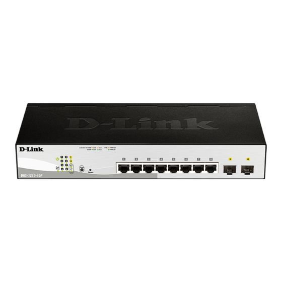
Page 8: Dgs-1210-10P
Port PoE LED (1-8): When mode LED lights up in PoE mode, the port LEDs indicate powering status over the corresponding port. DGS-1210-10P can supply up to 30W on port 1- 4, which are marked with black background color on front panel, for IEEE802.3at compliance PDs. -
Page 9: Front Panel
1 Product Introduction D-Link Web Smart Switch User Manual Front Panel Figure 1.3 – DGS-1210-20 Front Panel Power LED : The Power LED lights up when the Switch is connected to a power source. Port Link/Act/Speed LED (1-16, 17F, 18F, 19F, 20F): The Link/Act/Speed LED flashes, which indicates a network link through the corresponding port. -
Page 10: Rear Panel
1 Product Introduction D-Link Web Smart Switch User Manual Rear Panel Figure 1.6 – DGS-1210-28 Rear Panel Power: Connect the supplied AC power cable to this port. DGS-1210-28P 24-Port 10/100/1000Mbps plus 4 SFP ports Web Smart PoE Switch. Front Panel Figure 2.7 –... -
Page 11: Front Panel
1 Product Introduction D-Link Web Smart Switch User Manual Front Panel Figure 1.9 – DGS-1210-52 Front Panel Power LED : The Power LED lights up when the Switch is connected to a power source. Port Link/Act/Speed LED (1-48, 49F, 50F, 51F, 52F): The Link/Act/Speed LED flashes, which indicates a network link through the corresponding port. -
Page 12: Hardware Installation
D-Link Web Smart Switch User Manual Hardware Installation This chapter provides unpacking and installation information for the D-Link Web-Smart Switch. Step 1: Unpacking Open the shipping carton and carefully unpack its contents. Please consult the packing list located in the User Manual to make sure all items are present and undamaged. -
Page 13: Step 3 - Plugging In The Ac Power Cord
2 Hardware Installation D-Link Web Smart Switch User Manual Then, use the screws provided with the equipment rack to mount the switch in the rack. Figure 2.3 – Mount the Switch in the rack or chassis Please be aware of following safety Instructions when installing: A) Elevated Operating Ambient - If installed in a closed or multi-unit rack assembly, the operating ambient temperature of the rack environment may be greater than room ambient. -
Page 14: Power Failure
2 Hardware Installation D-Link Web Smart Switch User Manual Power Failure As a precaution, the switch should be unplugged in case of power failure. When power is resumed, plug the switch back in. -
Page 15: Getting Started
This chapter introduces the management interface of D-Link Web-Smart Switch. Management Options The D-Link Web Smart Switch can be managed through any port on the device by using the Web-based Management, or through any PC using the SmartConsole Utility. Each switch must be assigned its own IP Address, which is used for communication with the Web-Based Management or a SNMP network manager. -
Page 16: Login Web-Based Management
English. Figure 3.3 – Logon Dialog Box Smart Wizard After a successful login, the Smart Wizard will guide you through essential settings of the D-Link Web Smart Switch. Please refer to the Smart Wizard Configuration section for details. Web-based Management By clicking the Exit button in the Smart Wizard, you will enter the Web-based Management interface. - Page 17 (where D:\ represents the drive letter of your CD-Rom) and click OK. Follow the on-screen instructions to install the utility. Upon completion, go to Start > Programs > D-Link SmartConsole Utility and open the SmartConsole Utility. Connect the Smart Switch to the same L2 network segment of your PC and use the SmartConsole Utility to discover the Smart Switches.
-
Page 18: Smartconsole Utility
D-Link Web Smart Switch User Manual SmartConsole Utility The D-Link SmartConsole Utility allows the administrator to quickly discover all D-Link smart switches, which are in the same domain of the PC, collect traps and log messages, and quick access to basic configurations of the switch. -
Page 19: Trap
Figure 4.3 – SmartConsole Log Trap By setting up in “Trap to SmartConsole Utility” in D-Link Web Smart switches, traps can be collected by the designated host PC with the SmartConsole Utility installed. Click this icon to launch the Trap window. Click View Trap to show the events of the SmartConsole Utility and the device. -
Page 20: Monitor List
4 SmartConsole Utility D-Link Web Smart Switch User Manual Monitor List By clicking on this icon you will see below options: Figure 4.5 – SmartConsole Monitor List Save: Records the setting of the Device List as default for the next time the SmartConsole Utility is used. - Page 21 4 SmartConsole Utility D-Link Web Smart Switch User Manual Figure 4.7 – SmartConsole Device Settings Password Setting Select a switch from the Device List. Click on this icon to launch the Password Setting window. Here you can enter a new password and confirm it.
-
Page 22: Add(+), Delete(-) And Discover The Device
4 SmartConsole Utility D-Link Web Smart Switch User Manual Figure 4.9 – Firmware Upgrade CAUTION: Do not disconnect the PC or remove the power cord from the device until the upgrade completes. The software may be corrupted because of the incomplete firmware upgrade. -
Page 23: Device List
4 SmartConsole Utility D-Link Web Smart Switch User Manual Figure 4.11 – SmartConsole Add device Figure 4.12 – SmartConsole Delete device Device List This list displays all discovered Web-Smart devices on the network. Figure 4.13 – SmartConsole Device List Definitions of the Device List features: Select: Click the Select to choose a switch for configuration settings. - Page 24 4 SmartConsole Utility D-Link Web Smart Switch User Manual again. NOTE: If the IP address of device is showed with IPv6 address, then it can not be configured with Smartconsole Utility. The user needs to double click the selected device and login the web for...
-
Page 25: Configuration
5 Configuration D-Link Web Smart Switch User Manual Configuration The features and functions of the D-Link Web Smart Switch can be configured for optimum use through the Web-based Management Utility. Smart Wizard Configuration After a successful login, the Smart Wizard will guide you through essential settings of the D-Link Web Smart Switch. -
Page 26: Snmp
5 Configuration D-Link Web Smart Switch User Manual Figure 5.2 – Password in Smart Wizard SNMP The SNMP Setting allows you to quickly enable/disable the SNMP function. The default SNMP Setting is Disabled. Click Enabled and then click Apply to make it effective. - Page 27 5 Configuration D-Link Web Smart Switch User Manual Figure 5.4 – Confirm the changes of IP address in Smart Wizard...
-
Page 28: Web-Based Management
Logout button first, then it will be seen as an abnormal exit and the login session will still be occupied. Finally, by clicking on the D-Link logo at the upper-left corner of the screen you will be redirected to the local D-Link website. -
Page 29: Tool Bar > Save Menu
5 Configuration D-Link Web Smart Switch User Manual Tool Bar > Save Menu The Save Menu provides Save Configuration and Save Log functions. Figure 5.6 – Save Menu Save Configuration Select to save the entire configuration changes you have made to the device to switch’s non-volatile RAM. -
Page 30: Configuration Backup And Restore
5 Configuration D-Link Web Smart Switch User Manual Figure 5.12 – Tool Menu > Reboot Device Configuration Backup and Restore Allow the current configuration settings to be saved to a file (not including the password), and if necessary, you can restore configuration settings from this file. Two methods can be selected: HTTP or TFTP. -
Page 31: Tool Bar > Smart Wizard
Tool Bar > Online Help The Online Help provides two ways of online support: D-Link Support Site will lead you to the D-Link website where you can find online resources such as updated firmware images; User Guide can offer an immediate reference for the feature definition or configuration guide. - Page 32 5 Configuration D-Link Web Smart Switch User Manual Figure 5.16 – User Guide Micro Site...
-
Page 33: Function Tree
5 Configuration D-Link Web Smart Switch User Manual Function Tree All configuration options on the switch are accessed through the Setup menu on the left side of the screen. Click on the setup item that you want to configure. The following sections provide more detailed description of each feature and function. -
Page 34: System > System Settings
30 minutes, and the default setting is 5 minutes. Group Interval: The D-Link Web Smart Switch will routinely send report packets to the SmartConsole Utility in order to maintain the information integrity. The user can adjust the Group Interval to optimal frequency. -
Page 35: System > Ipv6 System Settings
5 Configuration D-Link Web Smart Switch User Manual Figure 5.19 – System > System Settings System > IPv6 System Settings The IPv6 System Settings page allow user to configure the IPv6 system information. Figure 5.20 – System > IPv6 System Settings IPv6 System Settings: Interface Name: Displays the interface name of IPv6. -
Page 36: System > Ipv6 Neighbor Settings
5 Configuration D-Link Web Smart Switch User Manual Figure 5.21 – System > IPv6 Route Settings IP Interface: Specify the IP interface which to be created. Default Gateway: The corresponding IPv6 address for the next hop Gateway address in IPv6 format.. -
Page 37: System > Port Settings
5 Configuration D-Link Web Smart Switch User Manual Figure 5.23 – System > Password Access Control System > Port Settings In the Port Setting page, the status of all ports can be monitored and adjusted for optimum configuration. By selecting a range of ports (From Port and To Port), the Speed can be set for all selected ports by clicking Apply. -
Page 38: System > Syslog Host
5 Configuration D-Link Web Smart Switch User Manual Figure 5.25 – System > DHCP Auto Configuration System > SysLog Host System Logs record and manage events, as well as report errors and informational messages. Message severity determines a set of event messages that will be sent. Click Enable so you can start to configure the related settings of the remote system log server, then press Apply for the changes to take effect Figure 5.26 –... -
Page 39: System > Power Saving
5 Configuration D-Link Web Smart Switch User Manual Date: Select Date and specifies the From Day and To Day of the time profile. Click Add to create a new time profile or click Delete to delete a time profile from the table. -
Page 40: Vlan > 802.1Q Vlan
5 Configuration D-Link Web Smart Switch User Manual IEEE802.3az EEE compliance. By default, the switch enabled the 802.3az EEE function. Users can disable this feature by individual port via the IEEE802.3az EEE setting page. Figure 5.29 – System > IEEE802.3az EEE Settings From Port / To Port: A consecutive group of ports may be configured starting with the selected port. -
Page 41: Vlan > 802.1Q Vlan Pvid
5 Configuration D-Link Web Smart Switch User Manual Figure 5.31 – Configuration > 802.1Q VLAN > Add VLAN VLAN > 802.1Q VLAN PVID The 802.1Q VLAN PVID setting allows user to configure the PVID for each ports. Click Apply to implement changes made. - Page 42 5 Configuration D-Link Web Smart Switch User Manual Voice VLAN: Select to enable or disable Voice VLAN. The default is Disabled. After you enabled Voice VLAN, you can configure the Voice VLAN Global Settings. VLAN ID: The ID of VLAN that you want to assign voice traffic to. You must first create a VLAN from the 802.1Q VLAN page before you can assign a dedicated Voice VLAN.
-
Page 43: Vlan > Voice Vlan > Voice Vlan Port Settings
Similar as Voice VLAN, Auto Surveillance VLAN is a feature that allows you to automatically place the video traffic from D-Link IP cameras to an assigned VLAN to enhance the IP surveillance service. With a higher priority and individual VLAN, the quality and the security of surveillance traffic are guaranteed. The Auto Surveillance VLAN function will check the source MAC address / VLAN ID on the incoming packets. -
Page 44: L2 Functions > Jumbo Frame
L2 Functions > Jumbo Frame D-Link Gigabit Web Smart Switches support jumbo frames (frames larger than the Ethernet frame size of 1536 bytes) of up to 10,000 bytes (tagged). Default is disabled, Select Enabled then click Apply to turn on... -
Page 45: L2 Functions > Port Mirroring
5 Configuration D-Link Web Smart Switch User Manual Figure 5.38 – L2 Functions > Jumbo Frame L2 Functions > Port Mirroring Port Mirroring is a method of monitoring network traffic that forwards a copy of each incoming and/or outgoing packet from one port of the Switch to another port, where the packet can be studied. This enables network managers to better monitor network performances. -
Page 46: L2 Functions > Mac Address Table > Static Mac
5 Configuration D-Link Web Smart Switch User Manual Mode: Specifies Port-based or VLAN-based mode. If port-based mode is selected, the loop happening port will be shut down and affect all member VLANs. If VLAN-based mode is selected, only the member port in the loop happening VLAN will be shut down Interval (1-32767): Set a Loop detection Interval between 1 and 32767 seconds. - Page 47 5 Configuration D-Link Web Smart Switch User Manual STP. RSTP can operate with legacy equipment implementing IEEE 802.1D, however the advantages of using RSTP will be lost. The IEEE 802.1w Rapid Spanning Tree Protocol (RSTP) evolved from the 802.1D STP standard. RSTP was developed in order to overcome some limitations of STP that impede the function of some recent switching innovations.
-
Page 48: L2 Functions > Spanning Tree > Stp Port Settings
5 Configuration D-Link Web Smart Switch User Manual L2 Functions > Spanning Tree > STP Port Settings STP can be set up on a port per port basis. In addition to setting Spanning Tree parameters for use on the switch level, the Switch allows for the configuration of the groups of ports, each port-group of which will have its own spanning tree, and will require some of its own configuration settings. -
Page 49: L2 Functions > Link Aggregation > Port Trunking
5 Configuration D-Link Web Smart Switch User Manual port is forced to half-duplex operation) the p2p status changes to operate as if the p2p value were False. The default setting for this parameter is Auto. Restricted Role: Toggle between True and False to set the restricted role state of the packet. If set to True, the port will never be selected to be the Root port. -
Page 50: L2 Functions > Multicast > Igmp Snooping
5 Configuration D-Link Web Smart Switch User Manual To Port: The ending of a consecutive group of ports may be configured starting with the selected port. Activity: There are two different roles of LACP ports: Active - Active LACP ports are capable of processing and sending LACP control frames. This allows LACP compliant devices to negotiate the aggregated link so the group may be changed dynamically as needs require. -
Page 51: L2 Functions > Multicast > Multicast Forwarding
Figure 5.48 – L2 Functions > Multicast > IGMP Snooping VLAN Settings State : Specify the State to be enabled or disabled. Querier State: D-Link Smart Switch is able to send out the IGMP Queries to check the status of multicast clients. Default is disabled. -
Page 52: L2 Functions > Multicast > Multicast Filtering Mode
5 Configuration D-Link Web Smart Switch User Manual Figure 5.49 – L2 Functions > Multicast > Multicast Forwarding VID: The VLAN ID of the VLAN to which the corresponding MAC address belongs. Multicast MAC Address: The MAC address of the static source of multicast packets. This must be a multicast MAC address. -
Page 53: L2 Functions > Sntp > Timezone Settings
5 Configuration D-Link Web Smart Switch User Manual Figure 5.51 – L2 Functions > SNTP > Time Settings Clock Source: Specify the clock source by which the system time is set. The possible options are: Local - Indicates that the system time is set locally by the device. -
Page 54: L2 Functions > Lldp > Lldp Global Settings
5 Configuration D-Link Web Smart Switch User Manual Time Zone Offset GMT +/- HH:MM: Use these drop-down menus to specify your local time zone's offset from Greenwich Mean Time (GMT.) Daylight Saving Time Settings: From: Month / Day: Enter the month DST and date DST will start on, each year. -
Page 55: L2 Functions > Lldp > Lldp Port Settings
5 Configuration D-Link Web Smart Switch User Manual Figure 5.54 – L2 Functions > LLDP > LLDP MED Settings L2 Functions > LLDP > LLDP Port Settings The Basic LLDP Port Settings page displays LLDP port information and contains parameters for configuring LLDP port settings. -
Page 56: L2 Functions > Lldp > 802.1 Extension Tlv
5 Configuration D-Link Web Smart Switch User Manual Disabled – Disables the System Capabilities TLV on the port. Define these parameter fields. Click Apply to implement changes made and click Refresh to refresh the table information. L2 Functions > LLDP > 802.1 Extension TLV This 802.1 Extension TLV page is used to configure the LLDP Port settings. -
Page 57: L2 Functions > Lldp > Lldp Management Address Settings
5 Configuration D-Link Web Smart Switch User Manual Power via MDI: Advertises the Power via MDI implementations supported by the port. The possible field values are: Enabled – Enables the Power via MDI configured on the port. Disabled – Disables the Power via MDI configured on the port. -
Page 58: L2 Functions > Lldp > Lldp Local Port Table
5 Configuration D-Link Web Smart Switch User Manual Management Address: Select IPv4 or IPv6 address and enter the IP address. Click Search and the table will update and display the values required. Subtype: Displays the managed address subtype. For example, MAC address or IPv4 address. -
Page 59: L2 Functions > Lldp > Lldp Remote Port Table
5 Configuration D-Link Web Smart Switch User Manual Figure 5.62 – L2 Functions > LLDP > LLDP Local Port Detailed Table L2 Functions > LLDP > LLDP Remote Port Table This LLDP Remote Port Table page is used to display the LLDP Remote Port Brief Table. Select port number and click Search to display additional information. -
Page 60: L2 Functions > Lldp > Lldp Statistics
5 Configuration D-Link Web Smart Switch User Manual Figure 5.64 – L2 Functions > LLDP > LLDP Remote Port Normal Table To view the detail settings for a remote port, click View Detailed and the following page displays. Figure 5.65 – L2 Functions > LLDP > LLDP Remote Port Detailed Table L2 Functions >... -
Page 61: Qos > Bandwidth Control
5 Configuration D-Link Web Smart Switch User Manual Figure 5.66 – L2 Functions > LLDP > LLDP Statistics The following information can be viewed: LLDP Statistics System: Displays the counters that refer to the whole switch. Last Change Time – Displays the time for when the last change entry was last deleted or added. It is also displays the time elapsed since last change was detected. -
Page 62: Qos > 802.1P/Dscp/Tos
5 Configuration D-Link Web Smart Switch User Manual Figure 5.67 – QoS > Bandwidth Control From Port / To Port: A consecutive group of ports may be configured starting with the selected port. Type: This drop-down menu allows you to select between RX (receive), TX (transmit), and Both. This setting will determine whether the bandwidth ceiling is applied to receiving, transmitting, or both receiving and transmitting packets. -
Page 63: Qos > Ipv6 Traffic Class Priority Settings
5 Configuration D-Link Web Smart Switch User Manual WRR: Use the weighted round-robin (WRR) algorithm to handle packets in an even distribution in priority classes of service. Click Apply for the settings to take effect. From Port / To Port: Defines the port range which the port packet priorities are defined. -
Page 64: Security > Port Security
5 Configuration D-Link Web Smart Switch User Manual Trusted Host: Specify the Trusted Host to be enabled or disabled. The default is disabled. To define a management station IP setting, click the Add button and type in the IP address and Subnet mask. -
Page 65: Security > Safeguard Engine
Click Select All button to check all ports or click Clear button to uncheck all ports. Security > Safeguard Engine D-Link’s Safeguard Engine is a robust and innovative technology that automatically throttles the impact of packet flooding into the switch's CPU. This function helps protect the Web-Smart Switch from being interrupted by malicious viruses or worm attacks. -
Page 66: Security > Dhcp Server Screening
5 Configuration D-Link Web Smart Switch User Manual Figure 5.76 – Security > ARP Spoofing Prevention Enter the IP Address, MAC Address, Ports and then click Add to create a checking/filtering rule. Click Delete to remove an existing rule and Delete All to clear all the entries. -
Page 67: Security > Smart Binding > Smart Binding Settings
5 Configuration D-Link Web Smart Switch User Manual Figure 5.78 – Security > SSL Settings NOTE: When SSL is enabled, it will take longer time to open a web page due to encryption. After saving configuration, please wait around 10 seconds for the system summery page. -
Page 68: Security > Smart Binding > Smart Binding
5 Configuration D-Link Web Smart Switch User Manual will inspect all incoming ARP and IP packets and compare them to the IMPB white list. If the IP-MAC pair find a match in the white list, the packets from that MAC address are unblocked. If not, the MAC address will stay blocked. -
Page 69: Security > Smart Binding > Black List
5 Configuration D-Link Web Smart Switch User Manual Select the check box of entry then click Delete to remove it. Click Select All to select all entries of the table or click Clean to select none entries. Please keep at least one management host in the White List. - Page 70 5 Configuration D-Link Web Smart Switch User Manual Figure 5.83 – Security > 802.1X > 802.1X Settings By default, 802.1X is disabled. To use EAP for security, select enabled and set the 802.1X Global Settings for the Radius Server and applicable authentication information.
-
Page 71: Acl > Acl Wizard
5 Configuration D-Link Web Smart Switch User Manual state of the port transitions from down to up, or when an EAPOL-start frame is received. The Switch then requests the identity of the client and begins relaying authentication messages between the client and the authentication server. -
Page 72: Acl > Acl Profile List
5 Configuration D-Link Web Smart Switch User Manual Ports: Enter a range of ports to be configured. Press Apply for the settings to take effect. NOTE: Once the ACL rules conflict, rules with the smaller rule ID will take higher priority. - Page 73 5 Configuration D-Link Web Smart Switch User Manual Figure 5.86 – Add Access Profile The steps of adding an access profile are described below: 1) After selecting the Profile ID and Frame Type (MAC, IPv4 or IPv6), specify attributes like Untagged/Tagged (for MAC), ICMP/IGMP/TCP/UDP (for IPv4), or ICMP/TCP/UDP (for IPv6).
- Page 74 5 Configuration D-Link Web Smart Switch User Manual Select frame type based on MAC address, IPv4 address, IPv6 address or packet content. This will change the window according to the requirements for the type of profile. Select MAC ACL to instruct the Switch to examine the layer 2 part of each packet header.
- Page 75 5 Configuration D-Link Web Smart Switch User Manual Figure 5.88 – Add Access Profile (MAC ACL) The Add ACL Profile MAC ACL contains the following fields: Field Description Enter a MAC address mask for the source MAC address, e.g. FF-FF-FF- Source MAC Mask FF-FF-FF.
- Page 76 5 Configuration D-Link Web Smart Switch User Manual Figure 5.89 – Add Access Profile (IPv4 ACL ICMP) The Add ACL Profile IPv4 ACL ICMP address page contains the following fields: Field Description Defines the range of source IP addresses, relevant to the ACL rules.
- Page 77 5 Configuration D-Link Web Smart Switch User Manual Figure 5.90 – Add Access Profile (IPv4 ACL IGMP) Click Add button then the ACL profile is added. To define the IPv4 ACL TCP profile: Select IPv4 ACL with TCP and click Select button. The updates to show the follows: Figure 5.91 –...
- Page 78 5 Configuration D-Link Web Smart Switch User Manual The Add ACL Profile IPv4 ACL TCP port page contains the following fields: Field Description Source Port Mask Defines the range of source Ports relevant to the ACL rules. (0=ignore, 1=check). For example, to set 0 – 15, set mask of FFF0.
- Page 79 5 Configuration D-Link Web Smart Switch User Manual To define the IPv6 ACL ICMP profile: Select IPv6 ACL with ICMP and click Select button. The updates to show the follows: Figure 5.93 – Add Access Profile (IPv6 ACL ICMP) The Add ACL Profile IPv6 ACL ICMP address page contains the following fields:...
- Page 80 5 Configuration D-Link Web Smart Switch User Manual Figure 5.94 – Add Access Profile (IPv6 ACL TCP) The Add ACL Profile IPv6 ACL TCP port page contains the following fields: Field Description Source Port Mask Defines the range of source Ports relevant to the ACL rules. (0=ignore, 1=check).
- Page 81 5 Configuration D-Link Web Smart Switch User Manual Figure 5.95 – Add Access Profile (IPv6 ACL UDP) The Add ACL Profile IPv6 ACL UDP port page contains the following fields: Field Description Source Port Mask Defines the range of source Ports relevant to the ACL rules. (0=ignore, 1=check).
- Page 82 5 Configuration D-Link Web Smart Switch User Manual 3) After the Profile ID has been created, click Continue to go back to the main Access Profile List page, clicking the Edit / New Rules button to enter the Access Rule List page.
-
Page 83: Acl > Acl Finder
To delete an entry click the corresponding Delete button. Figure 5.100 – ACL > ACL Finder PoE > PoE Global Settings (DGS-1210-10P/28P only) This page will display the PoE status including System Budget Power, Support Total Power, Remainder Power, and The ratio of system power supply. -
Page 84: Poe > Poe Port Settings (Dgs-1210-10P/28P Only)
Current (mA), Classification, Port Status. You can select From Port / To Port to control the PoE functions of a port. DGS-1210-10P/28P will auto disable the ports if port current is over 375mA in 802.3af mode or 625mA in pre-802.3at mode. -
Page 85: Snmp > Trap To Smartconsole Utility
Power Limit: This function allows you to manually set the port power current limitation to be given to the PD. To protect the DGS-1210-10P/28P and the connected devices, the power limit function will disable the PoE function of the port when the power is overloaded. Select from "Class 1", "Class 2", "Class 3", “Class 4”... -
Page 86: Snmp > Snmp > Snmp Global Settings
PoE Over Max Power Budget: When the system supplies power to PDs and hits the max PoE power budget of 78watts and 185watts, the system will send out this trap message. (Only for DGS-1210-10P/28P) SNMP > SNMP > SNMP Global Settings Simple Network Management Protocol (SNMP) is an OSI Layer 7 (Application Layer) protocol designed specifically for managing and monitoring network devices. -
Page 87: Snmp > Snmp > Snmp User
5 Configuration D-Link Web Smart Switch User Manual SNMP > SNMP > SNMP User This page is used to maintain the SNMP user table for the use of SNMPv3. SNMPv3 allows or restricts users using the MIB OID, and also encrypts the SNMP messages sent out between users and Switch. -
Page 88: Snmp > Snmp > Snmp View
5 Configuration D-Link Web Smart Switch User Manual Figure 5.106 – SNMP > SNMP > SNMP Group Table SNMP > SNMP > SNMP View This page allows you to maintain SNMP views to community strings that define the MIB objects which can be accessed by a remote SNMP manager. -
Page 89: Snmp > Snmp > Snmp Host
5 Configuration D-Link Web Smart Switch User Manual SNMP > SNMP > SNMP Host This SNMP Host page is to configure the SNMP trap recipients. Figure 5.109 – SNMP > SNMP > SNMP Host Host IP Address: Select IPv4 or IPv6 and specify the IP address of SNMP management host. -
Page 90: Snmp > Rmon > Rmon History
5 Configuration D-Link Web Smart Switch User Manual Index (1 - 65535): Indicates the RMON Ethernet Statistics entry number. Port: Specifies the port from which the RMON information was taken. Owner: Displays the RMON station or user that requested the RMON information. -
Page 91: Snmp > Rmon > Rmon Event
5 Configuration D-Link Web Smart Switch User Manual Sample type: Defines the sampling method for the selected variable and comparing the value against the thresholds. The possible field values are: Delta value – Subtracts the last sampled value from the current value. The difference in the values is compared to the threshold. -
Page 92: Monitoring > Cable Diagnostics
5 Configuration D-Link Web Smart Switch User Manual Clear: To reset the details displayed. TxOK: Number of packets transmitted successfully. RxOK: Number of packets received successfully. TxError: Number of transmitted packets resulting in error. RxError: Number of received packets resulting in error. -
Page 93: Monitoring > System Log
5 Configuration D-Link Web Smart Switch User Manual NOTE: Cable length detection is effective on Gigabit ports only. NOTE: Please be sure that Power Saving feature is disabled before enabling Cable Diagnostics function. Monitoring > System Log The System Log page provides information about system logs, including information when the device was booted, how the ports are operating, when users logged in, when sessions timed out, as well as other system information. -
Page 94: Command Line Interface
D-Link Web Smart Switch User Manual Command Line Interface The D-Link Web Smart Switch allows a computer or terminal to perform some basic monitoring and configuration tasks by using the Command Line Interface (CLI) via TELNET protocol. To connect a switch via TELNET: 1. -
Page 95: Download
6 Command Line Interface D-Link Web Smart Switch User Manual Command Parameter save debug info Each command is listed in detail, as follows: Purpose To display a list of commands. Syntax The ? command displays a list of commands of the switch. -
Page 96: Upload
6 Command Line Interface D-Link Web Smart Switch User Manual cfg_fromTFTP − Download a switch configuration file from a TFTP server.− The IPv4 address of the TFTP server. − The IPv6 address of the TFTP server. − The filename of the firmware or switch configuration file on the TFTP server. -
Page 97: Config Ipif System
6 Command Line Interface D-Link Web Smart Switch User Manual firmware_toTFTP − Upload the firmware on the Switch from a Parameters TFTP server. cfg_toTFTP − Specifies that the Switch’s current settings will be uploaded to the TFTP server.− The IPv4 address of the TFTP server. -
Page 98: Config Ipif System
6 Command Line Interface D-Link Web Smart Switch User Manual DGS-1210-52> config ipif system Purpose To configure the System IPv6 interface. Syntax config ipif system { ipv6 ipv6address| dhcpv6_client [enable | disable] } The c onfig ipif s ys tem command configures the System IPv6 Description interface on the Switch. -
Page 99: Ping Ip Address 3000::1
6 Command Line Interface D-Link Web Smart Switch User Manual The ping command checks if another IP address is reachable on Description the network. You can ping the IP address connected to through the managed VLAN (VLAN 1 by default), as long as there is a physical path between the switch and the target IP equipment. -
Page 100: Reboot
6 Command Line Interface D-Link Web Smart Switch User Manual reboot Purpose To reboot the Switch. If the Switch is a member of a stack, it may be rebooted individually, without affecting the other members of the stack. reboot Syntax The reboot c ommand reboots the system. -
Page 101: Show Switch
6 Command Line Interface D-Link Web Smart Switch User Manual IP Setting Mode : Static IP Address : 10.90.90.90 Subnet Mask : 255.0.0.0 Default Gateway : 0.0.0.0 DHCPv6 Client State : Disabled IPv6 Global Unicast Address: 3ffe:501:ffff:100:100::1/64 DGS-1210-52> show switch Purpose To display information about the Switch. -
Page 102: Save
6 Command Line Interface D-Link Web Smart Switch User Manual Example usage: To configure the account admin password: DGS-1210-52> c onfig ac c ount admin pas s word 1234 DGS-1210-52> save Purpose To save changes in the Switch’s configuration to non-volatile RAM. - Page 103 6 Command Line Interface D-Link Web Smart Switch User Manual 10.90.90.98 00:19:5b:14:3d:c4 ARPA vlan1 Dynamic 10.255.255.255 ff:ff:ff:ff:ff:ff ARPA vlan1 Static % MAC table : Vlan Mac Address Type Ports ------ -------------------- -------- ------- 00:00:00:00:00:26 Learnt Gi0/7 Total Mac Addresses displayed: 1...
-
Page 104: Appendix A - Ethernet Technology
Appendix A - Ethernet Technology D-Link Web Smart Switch User Manual Appendix A - Ethernet Technology This chapter will describe the features of the D-Link Web Smart Switch and provide some background information about Ethernet/Fast Ethernet/Gigabit Ethernet switching technology. Gigabit Ethernet Technology Gigabit Ethernet is an extension of IEEE 802.3 Ethernet utilizing the same packet structure, format, and... -
Page 105: Appendix B - Technical Specifications
Safety Certifications Duplex mode cUL, LVD, CE - Auto MDI/MDIX - IEEE802.3af Power over Ethernet on Port 1 ~ Port 8 GE ports (DGS-1210-10P only) Features - IEEE802.3af Power over Ethernet on Port L2 Features 1~ Port 24 GE ports (DGS-1210-28P) Supports up to 16K MAC address - IEEE802.3at Power over Ethernet on Port... -
Page 106: Vlan
D-Link Web Smart Switch User Manual Loopback Detection Security 802.3ad Link Aggregation: Trusted Host - DGS-1210-10P: Supports max 5 groups Port Security:Support 64 MAC addresses per device and 8 ports per group per port Traffic Segmentation - DGS-1210-20: Supports max 10 groups... - Page 107 Appendix B - Technical Specifications D-Link Web Smart Switch User Manual - By Port Standby: Each port on the system enters sleep state by schedule. - By System Hibernation: System enters hibernation by schedule. In this mode, switches save most power since main...
-
Page 108: Appendix C - Rack Mount Instructions
Appendix C – Rack mount Instructions D-Link Web Smart Switch User Manual Appendix C – Rack mount Instructions Safety Instructions - Rack Mount Instructions - The following or similar rack-mount instructions are included with the installation instructions: A) Elevated Operating Ambient - If installed in a closed or multi-unit rack assembly, the operating ambient temperature of the rack environment may be greater than room ambient.