
Related Manuals for Husqvarna 1200


Summary of Contents for Husqvarna 1200
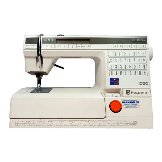
- Page 1 SERVICE MANUAL MODEL 1200, # 1 1100 1090 1070 1050 SEWKNITWORLD 104 72 30-26 Husqvarna service manual 1...
-
Page 2: Table Of Contents
Wiring diagram Service casette 14-17 Switch for presser foot lift Buttonhole meter Lower thread indicator Stepmotors: Thread tension, sewing head, guide, side motion Transformer 1050/1070/1090 Transformer 1100/1200 Electronic board 1050/1070/1090 Electronic board 1100/1200 SEWKNITWORLD 2 Husqvarna service manual 104 72 30-26... - Page 3 23 The sideways setting of the feeding mechanism Dismounting- and mounting instructions Rear cover, lower cover Front cover Parts of the front cover Parts of the front cover 1100/1200 program memory Parts of the front cover 1100/1200 foil keyboard Transformer Main motor Bobbin-stop...
-
Page 4: Survey Settings
SETTINGS SEWKNITWORLD 4 Husqvarna service manual 104 72 30-26... -
Page 5: User Instructions
ESD (=Electro Static Discharge). To avoid that these errors arise it is important to handle loose circuit boards in a controlled way. Always use wrist band 412 23 02-01 when servicing. wrist band position for wrist band SEWKNITWORLD 104 72 30-26 Husqvarna service manual 5... -
Page 6: Gauges And Service
7. Electronic unit for testing the function of the transformer and the stepmotors. See separate instructions enclosed. Ref. No 412 02 56-01. 8. Service casette for 1100, 1200 (P.14-15). Ref. No 412 17 29-15. SEWKNITWORLD 6 Husqvarna service manual 104 72 30-26... - Page 7 Ref. No 412 36 50-01. 9. Angle key for Torx 6 Ref. No 412 27 67-01. 10.Wristband for ESD Ref. No 412 23 02-01. 11.Extractor tool (p. 45). SEWKNITWORLD Ref. No 412 27 98-01. 104 72 30-26 Husqvarna service manual 7...
-
Page 8: Visual Control Of Details
”Care of the machine”. Action The faulty dog should be exchanged. Remove the stitch plate. Undo the screws and replace the feed dog. As regards to the settings of the feed dog (P.34-35). SEWKNITWORLD 8 Husqvarna service manual 104 72 30-26... -
Page 9: Bobbin Case
The inside of the hook cover forms a support for the hook and the bridge above the finger of the bobbin case supports the thread, so that the thread loop is formed on the correct side of the needle. SEWKNITWORLD 104 72 30-26 Husqvarna service manual 9... -
Page 10: Main Switch And Feed Dip Button
The main switch and feed dip button If the main switch or the feed dip button doesn’t work satisfactorily, remove the rear cover and front panel, (P.44). Exchange the complete unit or spring (A). SEWKNITWORLD 10 Husqvarna service manual 104 72 30-26... -
Page 11: Foot Control
Action Test the foot control on a machine that is known to operate properly. If it does not work, exchange the whole control, alternatively the potentiometer. Dismounting (page 49). SEWKNITWORLD 104 72 30-26 Husqvarna service manual 11... -
Page 12: Cog Belt, Short
The belt must not be damaged. Adjustment Loosen the nut (A) by means of a 10mm fixed spanner and shift the belt tension roller belt tension roller (B) until the required tension is obtained. Tighten the nut. SEWKNITWORLD 12 Husqvarna service manual 104 72 30-26... -
Page 13: Electronics
6 NEEDLE MOTOR 7 LOW THREAD INDICATOR 8 FEEDING MOTOR 9 SIDE MOTION MOTOR BE SURE THAT CABLES TO DRIVE-BOARD ARE CORRECTLY CONNECTED, BEFORE SWITCHING ON MAIN SUPPLY MODEL 1050/1090 MODEL 1070 MODEL 1100/1200/#1 SEWKNITWORLD 104 72 30-26 Husqvarna service manual 13... -
Page 14: Service Casette
To facilitate the control and setting of the different functions of the machine there is a service program. Handling -Get into the service program of the machine by holding the back feeding button and (-) stitch length pressed while turning on the main switch. SEWKNITWORLD 14 Husqvarna service manual 104 72 30-26... - Page 15 Functions on the service casette 1100, 1200 Key 1 Shown in the right display. Number of the program memory. Which casettes the program memory contains. Which casette is in the machine. Check can be made that the machine reads the correct casette being inserted.
- Page 16 Key 41 Is used when setting the stitch length balance. Setting no 20 (P. 37. The machine now sews the stitch 41 which shall have a rectangular look. NOTE! Not mentioned keys are not used at service or are without function. SEWKNITWORLD 16 Husqvarna service manual 104 72 30-26...
- Page 17 Key 39 Is used when setting the stitch length balance. Setting no 20 (P. 38). The machine now sews the stitch 39 which shall have a rectangular look. NOTE! Not mentioned keys are not used at service or are without function. SEWKNITWORLD 104 72 30-26 Husqvarna service manual 17...
-
Page 18: Switch For Presser Foot Lift
If the values are correct the fault is inside the circuit board or the connection between the circuit board and the LCD board. (Exceptionally the fault can also be inside the LCD board). SEWKNITWORLD 18 Husqvarna service manual 104 72 30-26... -
Page 19: Lower Thread Indicator
LCD board. You can check the indicator if you connect it to the circuit board (but don’t mount it) and hold a mirror in front of it. Photo transistor (receiver) IR-diode (emitter) Mirror SEWKNITWORLD 104 72 30-26 Husqvarna service manual 19... -
Page 20: Stepmotors: Thread Tension, Sewing Head, Guide, Side Motion
If the side feeding still does not work, check: - the cable connection of the step motor to the circuitboard, - the step motor, - the smooth-running of the feeding movement, - the circuit board, - the LCD board. SEWKNITWORLD 20 Husqvarna service manual 104 72 30-26... -
Page 21: Transformer 1050/1070/1090
1) New foot control 2) New motor (only connect to circuit board at check) 3) New circuit board 4) New transformer (if the machine doesn’t work at all) SEWKNITWORLD 104 72 30-26 Husqvarna service manual 21... -
Page 22: Transformer 1100/1200
-Driving of the step motor of the sewing head, -Driving of the step motor of the guide, -Driving of the step motor of the thread tension, -Driving of the step motor of the side motion, applies for model 1200, -Arm shaft sensor, -Buttonhole meter,... -
Page 23: Setting Instructions
Gap between the hook cover and the driver, (P.24). Timing of the hook in relation to the needle, (P.30). Gap between hook and the needle, (P.28). Setting the stitch plate in relation to the needle, (P.29). SEWKNITWORLD 104 72 30-26 Husqvarna service manual 23... -
Page 24: The Gap Between The Hook Cover And The Driver
Thereafter check: The gap between the hook and the needle (P.28). Setting of the stitch plate in relation to the needle, (P.29). SEWKNITWORLD 24 Husqvarna service manual 104 72 30-26... -
Page 25: Presser Foot, Parallelism To The Stitch Plate
On the underneath of the buttonhole foot there is a guide, which steers the fabric. If the position of the presser foot is not correct in relation to the needle, the distance between the columns will be affected. SEWKNITWORLD 104 72 30-26 Husqvarna service manual 25... -
Page 26: Setting Of The Stepmotor Of The Sewing Head
Thereafter set: Setting the presser foot at right angles to the feeding direction (P.25). The gap between the hook and the needle (P.28). Setting the stitch plate in relation to the needle (P.29). SEWKNITWORLD 26 Husqvarna service manual 104 72 30-26... -
Page 27: Setting Of The Needle In Relation To The Presser Foot
Check the setting by switching mains on and off a couple of times. Thereafter check: The gap between the hook and the needle (P.28). Setting of the stitch plate in relation to the needle (P.29). SEWKNITWORLD 104 72 30-26 Husqvarna service manual 27... -
Page 28: The Gap Between The Hook And The Needle
Loosen the nut (A). Shift the sewing head by turning the lower adjustment nut (B) until the required position is reached. Hold the adjustment nut in position and tighten the locking nut. Check the setting. SEWKNITWORLD 28 Husqvarna service manual 104 72 30-26... -
Page 29: Setting The Stitch Plate In Relation To The Needle
90 is between points (A) and (B). Needle 80 will lie slightly behind the centre of the needle hole. NOTE! The angled position of the needle. SEWKNITWORLD 104 72 30-26 Husqvarna service manual 29... -
Page 30: Timing Of The Hook In Relation To The Needle
NOTE! The axial play of the arm shaft might change when loosening the screws. SEWKNITWORLD Maximum play may be 0,05 mm. 30 Husqvarna service manual 104 72 30-26... -
Page 31: Needle Height
Tighten the screw (A). NOTE! Check that the needle eye is at right angles to the hook by fitting a twin needle and observing the needle positions in the needle hole of the stitch plate. SEWKNITWORLD 104 72 30-26 Husqvarna service manual 31... -
Page 32: Thread Tension Of The Bobbin Case
Set the catch of the thread tension dial in the middle of the index. When test sewing with normal fabric and thread turn the adjustment screw until the correct SEWKNITWORLD take-up is obtained for straight stitching and zig-zag. 32 Husqvarna service manual 104 72 30-26... -
Page 33: Setting The Thread Tension Of The Step Motor
The stop in the adjustment casing, i.e. the limitation of the movement of the spring, can be adjusted by means of a screwdriver, which should be applied at the upper part of the casing. Exchange of the thread tension device. (P.52). SEWKNITWORLD 104 72 30-26 Husqvarna service manual 33... -
Page 34: Parallelism Of The Feed Dog
Adjustment Set the feed dog at its highest position. Put setting gauge 411 49 93-01 above the feed dog. Loosen nut (A) and turn the screw (B) until requirements is reached. SEWKNITWORLD 34 Husqvarna service manual 104 72 30-26... -
Page 35: The Lengthwise Movement Of The Feed Dog
Thereafter turn the scanner (B) until you switch off when there is an adequate amount of thread on the bobbin (see illustration). After the adjustment the scanner is secured from being turned by means of the locking ring. SEWKNITWORLD 104 72 30-26 Husqvarna service manual 35... - Page 36 Select menu D. Press button no 7 and turn the nut (A) until the machine sews a stitch D7 according to illustration. Check that both the columns of the buttonhole have the same tightness. SEWKNITWORLD 36 Husqvarna service manual 104 72 30-26...
- Page 37 41 according to illustration. Check the aspect of the follwing signs: C, D, B, P, S, T, 8 and that both columns of the buttonhole have the same tightness. SEWKNITWORLD 104 72 30-26 Husqvarna service manual 37...
- Page 38 39 according to illustration. Check the aspect of the follwing signs: C, D, B, P, S, T, 8 and that both columns of the buttonhole have the same tightness. SEWKNITWORLD 38 Husqvarna service manual 104 72 30-26...
- Page 39 Press button n12 on the service casette and turn the nut (A) until the machine sews a service buttonhole whose columns are of the same length (see illustration). Check the aspect of the folling signs: C,D,B,P,S,T,8 and that the columns of the buttonhole have the same tightness. SEWKNITWORLD 104 72 30-26 Husqvarna service manual 39...
- Page 40 20 The balance of the stitch - 1200 Requirements The machine shall sew patterns and letters according to the symbol. NOTE! When checking and adjusting the stitch length balance test sewing is to be carried out on a simple cotton cloth with pads (Stitch’n tear) and a thin and smooth...
-
Page 41: The Balance Of The Stitch Length
Get into the service mode of the machine by pressing the reverse feeding button and (-) stitch length while the main switch is turned on. For 1200 use the service casette and press button no 9. For 1050/1070/1090 press button no 7... -
Page 42: Pre-Setting Of The Step Motor Of The Side Motion
Loosen screw (A) and place the cog segment in such a way that pin (B) arrives in the middle of the opening of the cog segment (see fig. 2). Tighten screw (A). Check according to requirements. Fig.1 Fig. 2 SEWKNITWORLD 42 Husqvarna service manual 104 72 30-26... -
Page 43: The Sideways Setting Of The Feeding Mechanism
Loosen screws (A) and push the step motor unit with the feeding device sideways. Tighten the screws. Check the play according to requirements. NOTE! The spherical bearings (B) and (D) must be trued so that the feeding device can move easily. Min 0,3 Min 0,3 SEWKNITWORLD 104 72 30-26 Husqvarna service manual 43... -
Page 44: Front Cover
Fit the printed circuit for the guide into its place. Attach the display board under the hook on the lower edge, fit support (D) into its place. Fit the insulating plate and tighten the screws. Connect the cords. SEWKNITWORLD 44 Husqvarna service manual 104 72 30-26... -
Page 45: Parts Of The Front Cover 1100/1200 Program Memory
MEMO-CHIP 1100/1200 The Husqvarna 1100/1200 has an exchangeable memo-chip in which the characteristics and stitches of the machine are stored. Exchange of the memo-chip In order to be able to dismount without damaging the LCD-board a special extractor tool sshall be used. -
Page 46: Parts Of The Front Cover 1100/1200 Foil Keyboard
Dismount foil keyboard (C). Remove glue residues from the surface. Remount in reverse order. NOTE! When mounting code spring (A) an interlayer (B) is to be used between the code spring and the foil keyboard in order to avoid to damage the contact surfaces SEWKNITWORLD 46 Husqvarna service manual 104 72 30-26... -
Page 47: Transformer
- Remount the upper part and lower part of the transformer. - Try the transformer by means of the transformer tester (which is part of the diagnoser set 412 02 56-01). - Try the transformer in a sewing machine. SEWKNITWORLD 104 72 30-26 Husqvarna service manual 47... -
Page 48: Main Motor
Loosen all cables rearwisen from the circuit board. Loosen screws (A) and the screws (B) holding the plate of the arm shaft transmitter. Loosen the cable (D) for the transformer from the board. Wiring instruction (P. 13). SEWKNITWORLD 48 Husqvarna service manual 104 72 30-26... -
Page 49: Foot Control
Insert a screwdriver between the sections and carefully bend the pins (A) out of their positions. Part the sections. Push the plug (B) device out of the potentiometer (C). The potentiometer can now be dismounted. Mount in the reverse order. SEWKNITWORLD 104 72 30-26 Husqvarna service manual 49... -
Page 50: Feeding Guide Compl
Mount the feeding guide into the machine and thread the stud of the fork into the hole of the block. Tighten the screws (B). Tighten the nuts (A). Connect the cables to the circuit board. Mount the cable groove. Thereafter set: The stitch length balance (P.36-40). SEWKNITWORLD 50 Husqvarna service manual 104 72 30-26... -
Page 51: Connecting Rod
Mount the feeding guide compl. Fit the dolly (F) onto the stitch regulator fork and hook on the spring (A). Mount the clips of the side motion, for 1200. Mount the connecting rod. Mount the main motor. -
Page 52: Thread Tension Device Compl
The gap between the hook cover and the driver (P.24). The gap between the hook and the needle (P.28). Setting the stitch plate in relation to the needle (P.29) Setting the timing of the hook in relation to the needle (P.30). SEWKNITWORLD 52 Husqvarna service manual 104 72 30-26... -
Page 53: Lower Shaft
The lower shaft Dismounting Dismount transformer and motor. Dismount the side feeding mechanism, applicable to 1200 (P.56). Dismount the feeding mechanism compl. with the stitch regulator fork (P.51). Remover the belt stretcher for the long cog belt. Loosen screws (A) for the bearing clamp of the lower shaft. -
Page 54: Sewing Head
The setting of the presser foot at right angles to the feeding direction (P.25). The gap between the hook and the needle (P.28). The setting of the stitch plate in relation to the needle (P.29). The height of the needle (P.31). SEWKNITWORLD 54 Husqvarna service manual 104 72 30-26... -
Page 55: Arm Shaft
The gap between the hook and the needle (P.28). The setting of the stitch plate in relation to the needle (P.29). The timing of the hook in relation to the needle (P.30). SEWKNITWORLD 104 72 30-26 Husqvarna service manual 55... -
Page 56: Side Motion Mechanism Cpl
Mount in the reverse order. Thereafter set: - The pre-setting of the step motor of the side feeding (P.42). - The sideways setting of the feed dog (P.34). - The stitch length balance (P.40). SEWKNITWORLD 56 Husqvarna service manual 104 72 30-26... -
Page 57: Fault Finding Diagram
G. None of the keys of the machine functions. 1. Check that none of the keys of the machine stays pressed. 2. Replace the memo-chip (P.45). 3. Try a new LCD-board (P.44). SEWKNITWORLD 104 72 30-26 Husqvarna service manual 57... - Page 58 4. Check the signals of the circuit board to the step motor by means the diagnoster and replace the circuit board in case of error (P.48). 5. Replace feeding guide,compl. or step motor (P.50). SEWKNITWORLD 58 Husqvarna service manual 104 72 30-26...
- Page 59 3. Try a new micro switch or measure it according to the service manual (P.18). 4. Check the cables between the circuit board and the LCD-board. 5. Try a new circuit board (P.48). 6. Try a new LCD-board (P.44). SEWKNITWORLD 104 72 30-26 Husqvarna service manual 59...
- Page 60 Y. The machine sews straight stitching only backwards. 1. If there are not any further problems, replace the memo-chip (P.45). Z. All symbols flash on the diplay. 1. Replace the memo-chip (P.45). 2. Replace the LCD-board (P.44). SEWKNITWORLD 60 Husqvarna service manual 104 72 30-26...
- Page 61 SEWKNITWORLD 104 72 30-26 Husqvarna service manual 61...