Motorola APX 6000 User Manual
Hide thumbs
Also See for APX 6000:
- User manual (200 pages) ,
- Manual (105 pages) ,
- Service manual (438 pages)
Table of Contents
Table of Contents

Related Manuals for Motorola APX 6000


Summary of Contents for Motorola APX 6000
- Page 1 APX™ Two-Way Radios APX 6000 User Guide Model 3...
- Page 3 • Zone – Zone switch to desired zone. 4-Way Navigation Button Keypad • Channel – Channel switch to desired channel. *PMLN5717A* PMLN5717A © 2010 by Motorola, Inc. All Rights Reserved. 11/10 1301 E. Algonquin Rd., Schaumburg, English IL 60196-1078, U.S.A.
-
Page 4: Display Status Icons
The more stripes, the stronger the On steady = View mode Press and hold the PTT button. Speak clearly signal strength for the current site Blinking = Program mode into the microphone. (trunking only). On = Secure operation. Release the PTT button to end call. Direct radio to radio communication or Off = Clear operation. -
Page 5: Declaration Of Conformity
Address: 1301 East Algonquin Road, Schaumburg, IL 60196-1078, U.S.A. Phone Number: 1-800-927-2744 Hereby declares that the product: Model Name: APX 6000 conforms to the following regulations: FCC Part 15, subpart B, section 15.107(a), 15.107(d) and section 15.109(a) Class B Digital Device As a personal computer peripheral, this device complies with Part 15 of the FCC Rules. - Page 6 Note: This equipment has been tested and found to comply with the limits for a Class B digital device, pursuant to part 15 of the FCC Rules. These limits are designed to provide reasonable protection against harmful interference in a residential installation.
-
Page 7: Table Of Contents
Encrypted Integrated Data (EID) ....2 Contents SecureNet ....... . 2 What Your Dealer/System Administrator This User Guide contains all the information you need Can Tell You . - Page 8 Home Button ......14 Selecting a Radio Channel ....34 Data Feature Button .
- Page 9 Using the Talkgroup Call Feature (Conventional Making a Dynamic Priority Change (Conventional Operation Only) ......44 Scan Only) .
- Page 10 Removing a Priority Status from a Text Requesting an Over-the-Air Rekey (ASTRO Message ....... . 70 Conventional Only) .
- Page 11 Going Out of Range ......92 Selecting the Power Level ....102 Using the Site Trunking Feature .
- Page 12 Helpful Tips ......114 Appendix: Maritime Radio Use in the VHF Frequency Range ..... 119 Caring for Your Radio .
-
Page 13: Important Safety Information
Product Safety and RF Exposure booklet enclosed with your radio (Motorola Publication part number 6881095C98) to ensure compliance with RF energy exposure limits. For a list of Motorola-approved antennas, batteries, and other accessories, visit the following website: http://www.motorola.com/governmentandenterprise English... -
Page 14: Computer Software Copyrights
Laws in the written permission of Motorola. No part of this manual United States and other countries preserve for Motorola may be reproduced, distributed, or transmitted in any... -
Page 15: Getting Started
Notations Used in This Manual Getting Started Throughout the text in this publication, you will notice the use of Take a moment to review the following: WARNING, Caution, and Note. These notations are used to How to Use This Guide ......page 1 emphasize that safety hazards exist, and the care that must be Notations Used in This Manual . -
Page 16: Additional Performance Enhancement
The following are some of the latest creations designed to enhance the security, quality and efficiency of APX radios. SecureNet allows user to perform secured communications on an Analog or Motorola Data Communication (MDC) channel. Dynamic System Resilience (DSR) The MDC OTAR feature will allow users to perform OTAR activities on an MDC channel. -
Page 17: What Your Dealer/System Administrator Can Tell You
What Your Dealer/System Administrator Preparing Your Radio for Use Can Tell You Assemble your radio by following these steps: Check with your dealer or system administrator, if the radio is to Charging the Battery ......page 4 be operated in extremely cold temperatures (less than -20°C), Battery Charger . -
Page 18: Charging The Battery
The Motorola-approved battery shipped with your radio is uncharged. Prior to using a new battery, charge it for a minimum of 16 hours to ensure optimum capacity and performance. For a list of Motorola-authorized batteries available for use with your radio, see Accessories on page 118. Note: When charging a battery attached to a radio, turn the radio off to ensure a full charge. -
Page 19: Attaching The Antenna
Attaching the Antenna To remove the battery, turn the radio off. Squeeze With the radio turned off, set the antenna in its receptacle and the release latches on the turn clockwise to attach it to the radio. bottom of the battery until the battery releases from the radio. -
Page 20: Attaching The Accessory Connector Cover
Attaching the Accessory Connector Using the Carry Holder Cover The accessory connector is located on the antenna side of the Position the radio within radio. It is used to connect accessories to the radio. the carry holder with the Note: To prevent damage to the connector, shield it with the main speaker facing connector cover when not in use. -
Page 21: Turning On The Radio
Turning On the Radio To remove the radio from Rotate the On/Off/Volume Control Knob clockwise until you the carry holder, place the hear a click. tip of your fingers on the ledge of the carry holder and push at the bottom of the radio until the radio releases from it. -
Page 22: Adjusting The Volume
Adjusting the Volume To increase the volume, turn the On/Off/Volume Control Knob clockwise. Main Speaker To turn off the radio, rotate the On/Off/Volume Control Knob counterclockwise until you hear a click. To decrease the volume, turn this knob counterclockwise. Note: Ensure that the main speaker is pointed towards you for increased loudness and intelligibility, especially in areas with loud background noises. -
Page 23: Identifying Radio Controls
Identifying Radio Controls Take a moment to review the following: Radio Parts and Controls ..... . page 10 Programmable Features ..... . . page 11 Assignable Radio Functions . -
Page 24: Radio Parts And Controls
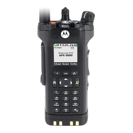
Radio Parts and Controls Antenna 16-Position Select Knob* On/Off/Volume Control Knob 3-Position A/B/C Switch* Top (Orange) Button* 2-Position Concentric Display Switch* Microphone Microphone Main Display Menu Select Top Side (Select) Buttons Button* Accessory Main Connector Speaker Push-to-Talk Data Feature (PTT) Button Bluetooth Button Pairing... -
Page 25: Programmable Features
Bluetooth Clear All Pairing – Allows you to clear all pairing Programmable Features info for Bluetooth. Any reference in this manual to a control that is Call Alert – Allows the radio to function like a pager, or to verify “preprogrammed”... - Page 26 Nuisance Delete – Temporarily removes an unwanted channel, Request-To-Talk (Conventional Only) – Notifies the except for priority channels or the designated transmit channel, dispatcher that you want to send a voice call. from the scan list. Scan – Toggles scan on or off. One Touch 1 –...
-
Page 27: Assignable Settings Or Utility Functions
Enhanced Zone Bank – Allows selection from a list of banks Accessing the Preprogrammed Functions with three different zones in each bank. You can access various radio functions through one of the Assignable Settings or Utility Functions following ways: Flip –... -
Page 28: Using The Navigation Buttons
Using the Navigation Buttons Data Feature Button Use this button to access data-related features, such as the Home Button Text Messaging Service (TMS) feature screen. button returns you to the Home (default) screen. In most 4-Way Navigation Button cases, this is the current mode. Use this button to scroll up, down, left or right. -
Page 29: Using The Keypad
Using the Keypad You can use the 3 x 4 alphanumeric keypad to access your radio’s features. The keypad functions in a manner similar to a standard telephone keypad when entering numeric digits. When the keypad is used to edit a list, each key can generate different characters of the alphabet. -
Page 30: Keypad Characters - Lowercase Mode
Keypad Characters – Lowercase Mode Number of Times Key is Pressed & “ ‘ Toggle between mixed case mode, uppercase mode, and lowercase mode. Space Toggle between numeric and letter mode. English... -
Page 31: Keypad Characters - Numeric Mode
Keypad Characters – Numeric Mode Number of Times Key is Pressed & “ ‘ Space Toggle between numeric and letter mode. English... -
Page 32: Keypad Characters - Hexadecimal Mode
Keypad Characters – Hexadecimal Mode Number of Times Key is Pressed Not applicable Not applicable English... -
Page 33: Push-To-Talk (Ptt) Button
Push-To-Talk (PTT) Button Identifying Status Indicators The PTT button on the side Your radio indicates its operational status through the following: of the radio serves two basic purposes: Status Icons ....... . . page 20 Text Messaging Service (TMS) Icons. -
Page 34: Status Icons
Status Icons Battery The number of bars (0 – 4) shown indicates the The 130 x 130 pixel front liquid crystal display (LCD) of your charge remaining in the battery. Blinks when the radio shows radio status, text entries, and menu entries. The Top Display battery is low. - Page 35 In-Call User Alert Priority Channel Scan • • On = The feature is enabled. Voice muting of Blinking dot = Radio detects activity on the affiliated trunking talkgroup or channel designated as selected conventional channel is Priority-One. Top Display activated. •...
- Page 36 Basic Zone Bank 2 AES Secure Operation Top Display • • D = Radio is in Zone 4. On = AES Secure operation. • • E = Radio is in Zone 5. Off = Clear operation. • • F = Radio is in Zone 6. Blinking = Receiving an encrypted voice call.
-
Page 37: Text Messaging Service (Tms) Icons
Text Messaging Service (TMS) Icons Hexadecimal Indicates that the text entry is currently in This feature allows you to send and receive text messages. See hexadecimal mode. Text Messaging Service (TMS) on page 66 for more Bluetooth On information. Bluetooth is on and ready for bluetooth connection. - Page 38 Read Message Request Reply The selected text message in the Inbox has been • The “Request Reply” feature is toggled on read. before the message is sent. Normal Message • Messages in the Inbox folder are flagged with User is composing a message with normal priority “Request Reply”.
-
Page 39: Tms Menu Options
TMS Menu Options Lowercase Indicates that the text entry is currently in Menu Option Description/Function lowercase mode. Back Brings you back to the previous screen. Deletes all messages. Deletes a message or text. Edit Brings you to the edit screen. Exit Exits to the Home screen. -
Page 40: Call Type Icons
Call Type Icons Landline phone number. The following icons appear on the radio’s main display, when you make or receive a call, or view selected call lists, to indicate the different call types associated with an alias or ID. Landline phone number added to a Call List. Radio number. -
Page 41: Led Indicator
Rapidly blinking red – Radio has failed the self test upon LED Indicator powering up or encountered a fatal error. The LED indicator shows the operational status of your radio. Solid yellow – Channel is busy. Blinking yellow – Radio is receiving a secured transmission. Solid green –... -
Page 42: Intelligent Lighting Indicators
Intelligent Lighting Indicators This feature temporary changes the backlight of the top display screen and the keypad, and adds a color bar to the main display screen to help signal that a radio event has occurred. Note: This feature must be preprogrammed by a qualified radio technician. Backlight and Bar Color Notification When... -
Page 43: Alert Tones
Alert Tones An alert tone is a sound or group of sounds. Your radio uses alert tones to inform you of your radio’s conditions. The following table lists these tones and when they occur. You Hear Tone Name Heard Radio Self Test Fail When radio fails its power-up self test. - Page 44 You Hear Tone Name Heard Valid Key-Press When correct key is pressed. Radio Self Test Pass When radio passes its power-up self test. Clear Voice At beginning of a non-coded communication. Short, Medium-Pitched Priority Channel When activity on a priority channel is received. Tone Received Emergency Alarm Entry...
- Page 45 You Hear Tone Name Heard Short, High-Pitched Low-Battery Chirp When battery is below preset threshold value. Tone (Chirp) Fast Ringing When system is searching for target of Private Call. Ringing Enhanced Call Sent When waiting for target of Private Call to answer the call. Phone Call Received When a land-to-mobile phone call is received.
-
Page 46: Phone Call Display And Alert Prompts
Phone Call Display and Alert Prompts The following appears on the radio’s display when you make and receive Phone calls. The radio also uses alert tones to indicate the current status. You Hear You See When Notes You press the PTT button and the No phone Press to hang up. -
Page 47: General Radio Operation
Selecting a Zone General Radio Operation A zone is a group of channels. Once you understand how your APX 6000 Portable is configured, you are ready to use your radio. 3-Position A/B/C Switch Use this navigation guide to familiarize yourself with the basic Call features: Selecting a Zone . -
Page 48: Selecting A Radio Channel
Selecting a Radio Channel Follow the procedure below. A channel is a group of radio characteristics, such as transmit/ < > to Zone. receive frequency pairs. Press the Menu Select button directly below Zone. to the required zone. Use the keypad to enter the zone number. If the zone number entered is unprogrammed, the display shows Invalid entry. -
Page 49: Receiving And Responding To A Radio Call
Procedure: Receiving and Responding to a Radio Call Turn the preprogrammed 16-Position Select knob to the desired channel. Once you have selected the required channel and/or zone, you can proceed to receive and respond to calls. Follow the procedure below. <... -
Page 50: Receiving And Responding To A Talkgroup Call
Receiving and Responding to a Talkgroup Call Receiving and Responding to a Private Call (Trunking Only) To receive a call from a group of users, your radio must be configured as part of that talkgroup. A Private Call is a call from an individual radio to another individual radio. -
Page 51: Receiving And Responding To A Telephone Call (Trunking Only)
Press the Menu Select button directly below Resp. Receiving and Responding to a Telephone Call (Trunking Only) Press the Call Response button within 20 seconds after the This feature allows you to receive calls similar to standard call indicators begin. phone calls from a landline phone. -
Page 52: Making A Radio Call
Making a Radio Call Hold the radio vertically 1 to 2 inches (2.5 to 5.0 cm) from your mouth. You can select a zone, channel, subscriber ID, or talkgroup by Press the PTT button to make the call. using: ASTRO Conventional Only: •... -
Page 53: Making An Enhanced Private Call (Trunking Only)
Press the Menu Select button directly below Call. The Making an Enhanced Private Call (Trunking Only) display shows the last transmitted or received ID. This feature allows you to send an individual Call Alert page if Press the Menu Select button directly below Cnts to scroll there is no answer from the target radio. -
Page 54: Making A Telephone Call (Trunking Only)
Press the PTT button to start the Private Call. Follow the procedure below. The display shows Calling.... < > to Phon. Hold the radio vertically 1 to 2 inches (2.5 to 5.0 cm) from Press the Menu Select button directly below Phon. The your mouth. -
Page 55: Repeater Or Direct Operation
Repeater or Direct Operation Monitoring Features The REPEATER operation increases the radio’s range by Radio users who switch from analog to digital radios often connecting with other radios through a repeater. The transmit assume that the lack of static on a digital channel is an and receive frequencies are different. -
Page 56: Conventional Mode Operation
Release the Volume Set button. Conventional Mode Operation Press and hold the PTT button to transmit. The LED lights ® Your radio may be preprogrammed to receive Private-Line up solid red. (PL) calls. Release the PTT button to receive (listen). Procedure: Momentarily press the Monitor button to listen for activity. -
Page 57: Advanced Features
Advanced Call Features Advanced Features Use this navigation guide to learn more about advanced Receiving and Making a Selective Call (ASTRO features available with your radio: Conventional Only) Advanced Call Features ..... . . page 43 This feature allows you to receive a call from or to call a specific Contacts . -
Page 58: Making A Selective Call
Release the PTT button to listen. Making a Selective Call Press to return to the Home screen. Procedure: Press the preprogrammed Quick Access (One-Touch) Selective Call button to dial the preprogrammed ID and Using the Talkgroup Call Feature (Conventional proceed to Step 4. Operation Only) This feature allows you to define a group of conventional Follow the procedure below. -
Page 59: Sending A Status Call
to Preset for the preset preprogrammed talkgroup. Sending a Status Call This feature allows you to send data calls to the dispatcher to the required talkgroup. about a predefined status. Each status can have up to a 14-character name. A maximum Use the keypad to enter the number of the corresponding of eight status conditions is possible. -
Page 60: Using The Dynamic Regrouping Feature (Trunking Only)
Procedure: When the dispatcher acknowledges, four tones sound and the display shows Ack received. The radio returns to When your radio is dynamically regrouped, it automatically normal dispatch operation. switches to the dynamically regrouped channel. A “gurgle” tone sounds and the display shows the dynamically If no acknowledgment is received, a low-pitched tone regrouped channel’s name. -
Page 61: Classifying Regrouped Radios
Contacts The display shows Reprgrm rqst and Please wait. If you hear five beeps, the dispatcher has acknowledged the This feature provides “address-book” capabilities on your radio. reprogram request. The display shows Ack received and Each entry corresponds to an alias (name) or ID (number) that the radio returns to the Home screen. -
Page 62: Making A Private Call From Contacts
Your radio also supports a maximum of 50 call lists. Each list to select the call type. can store up to 100 IDs (numbers). Hold the radio vertically 1 to 2 inches (2.5 to 5.0 cm) from Note: Your radio is preprogrammed with a number of your mouth. -
Page 63: Adding A New Contact Entry
Hold the radio vertically 1 to 2 inches (2.5 to 5.0 cm) from to Name and press the Menu Select button directly your mouth. below Edit. Press the PTT button to initiate the call. During the call, the The display shows Edit name and a blinking cursor display shows the subscriber alias. -
Page 64: Deleting A Contact Entry
The display shows Edit Number 1 and a blinking cursor Press the Menu Select button directly below Done once you appears. have finished. Use the keypad to enter the number. The display showsStored, confirming that the < Press to move one space to the left. -
Page 65: Adding A Contact To A Call List
Adding a Contact to a Call List Removing a Contact from a Call List Procedure: Procedure: < > < > to Cnts. to Cnts. Press the Menu Select button directly below Cnts. The Press the Menu Select button directly below Cnts. The entries are alphabetically sorted. -
Page 66: Editing A Contact In A Call List
Press the Menu Select button directly below Ok once you Editing a Contact in a Call List have finished. The display returns to the Edit Contact screen. Editing an Entry Alias Press the Menu Select button directly below Done to save Procedure: your changes and return to the main screen for Contacts. -
Page 67: Editing A Call Type
A blinking cursor appears. to Edit and press the Menu Select button directly Use the keypad to edit the name. below Sel. < Press to move one space to the left. to Type and press the Menu Select button directly >... -
Page 68: Scan Lists
Scan Lists Editing the Scan List This feature lets you change scan list members and priorities. Scan lists are created and assigned to individual channels/ Procedure: groups. Your radio scans for voice activity by cycling through Long press the preprogrammed Scan List Programming the channel/group sequence specified in the scan list for the button (side button) and proceed to Step 3. -
Page 69: Changing The Scan List Status
Use the keypad to go directly to additional channels to be Changing the Scan List Status added or deleted. Procedure: Use the 16-Position Select knob to select additional Long press the preprogrammed Scan List Programming channels to be added or deleted. button (side button). -
Page 70: Viewing And Changing The Priority Status
Scan Viewing and Changing the Priority Status Procedure: This feature allows you to monitor traffic on different channels Below the Sel, Del, and Rcl screen, press the Menu Select by scanning a preprogrammed list of channels. button directly below Sel to view and/or change the priority status of the currently displayed channel. -
Page 71: Making A Dynamic Priority Change (Conventional Scan Only)
Making a Dynamic Priority Change (Conventional < > to Nuis. Press the Menu Select button directly below Scan Only) Nuis. While the radio is scanning, the dynamic priority change feature The radio continues scanning the remaining channels in the allows you to temporarily change any channel in a scan list list. -
Page 72: Call Alert Paging
Call Alert Paging Sending a Call Alert Page Note: The radio automatically exits the feature, if the feature This feature allows your radio to work like a pager. inactivity timer is enabled, when the radio is left idle Even if other users are away from their radios, or if they are and the timer expires. - Page 73 If the call alert page is sent successfully, a tone sounds and Press the Menu Select button directly below Yes to send the display shows Ack received. the call alert page. If the call alert page is not acknowledged, a low tone sounds Press the Menu Select button directly below No to exit the and the display shows No acknowledge.
-
Page 74: Emergency Operation
Emergency Operation Sending an Emergency Alarm This feature allows you to send a data transmission, which The Emergency feature is used to indicate a critical situation. identifies the radio sending the emergency, to the dispatcher. If the Top (Orange) button is preprogrammed to send an Procedure: emergency signal, this signal overrides any other Press the preprogrammed Emergency button. -
Page 75: Sending An Emergency Call (Trunking Only)
Press and hold the preprogrammed Emergency button for Sending an Emergency Call (Trunking Only) about a second to exit the Emergency Call mode. This feature gives your radio priority access on a channel. Note: The radio operates in the normal dispatch manner Sending an Emergency Alarm with Emergency while in Emergency Call, except, if enabled, it returns Call... -
Page 76: Sending A Silent Emergency Alarm
Note: For ALL Emergency signals, when changing channels: Press and hold the PTT button. Speak clearly into the microphone. • If the new channel is also preprogrammed for Emergency, you can change channels while in Release the PTT button to end the transmission and wait for Emergency operation. -
Page 77: Automatic Registration Service (Ars)
Advanced Automatic Registration Service (ARS) Selecting or Changing the ARS Mode Procedure: This feature provides an automated data application registration Turn the preprogrammed 16-Position Select knob, once the for the radio. When you turn on the radio, the device zone you want is displayed, to the desired mode. automatically registers with the server. -
Page 78: Accessing The User Login Feature
Accessing the User Login Feature Logging In as a User This feature allows you as the user to be associated with the Procedure: radio. With this association, every data application (Example: Press the preprogrammed User Login button and proceed to Text Messaging Service) takes on a friendly username. -
Page 79: Logging Out
If the selected predefined username has more than eight (8) Wait for the logged in confirmation screen. If the login characters, or an invalid character in it, the display process is successful, the display shows the successful user momentary shows Invalid ID. Repeat Step 4. login indicator (IP indicator) icon and Logged in, with Logt and Exit. -
Page 80: Text Messaging Service (Tms)
Text Messaging Service (TMS) Accessing the TMS Features Note: The radio automatically exits the feature, if the feature This feature allows you to send and receive text messages. The inactivity timer is enabled, when the radio is left idle maximum length of characters for a text message is 200. and the timer expires. -
Page 81: Composing And Sending A New Text Message
A blinking cursor appears on the Compose screen. Composing and Sending a New Text Message Use the keypad to type or edit your message. Note: During the uppercase and lowercase mode, multi- < Press to move one space to the left. tapping the keys only scrolls through the letters. -
Page 82: Sending A Quick Text Message
Press to add a space. Sending a Quick Text Message Press to toggle between mixed case mode, uppercase Quick Text messages are messages that are predefined and mode, and lowercase mode. usually consist of messages that are used most frequently. Press to toggle between numeric and letter mode. - Page 83 The message appears on the Compose screen, with a Press to add a space. blinking cursor at the end of it. Press to toggle between mixed case mode, uppercase Use the keypad to edit the message, if required. mode, and lowercase mode. <...
-
Page 84: Using The Priority Status And Request Reply Features
Using the Priority Status and Request Reply Removing a Priority Status from a Text Message Features Procedure: Before sending your message, you can append a priority status After the outgoing message is composed (see Composing and and/or a request reply to your message. Sending a New Text Message on page 67 for more information): Appending a Priority Status to a Text Message... -
Page 85: Removing A Request Reply From A Text Message
to Mark Important and press the Menu Select Removing a Request Reply from a Text Message button directly below Sel to indicate the message as Procedure: important. After the outgoing message is composed (see Composing and to Req Reply and press the Menu Select button Sending a New Text Message on page 67 for more directly below Sel to request for a reply. -
Page 86: Managing Text Messages
Managing Text Messages Viewing a Text Message from the Inbox The Inbox can hold up to thirty (30) messages. Receiving a Text Message Note: to read the message if fills more than one Note: When you receive a message that is flagged with the screen. -
Page 87: Replying To A Received Text Message
The display shows a list of aliases or IDs, with the sender of to Text Message and press the Menu Select the latest received message on top. button directly below Sel. to the required aliases or ID and press the Menu to Quick Text and press the Menu Select button Select button below Sel to view the message. -
Page 88: Accessing The Drafts Folder
Edit Del. Back Press the Menu Select button directly below , or The display shows the Send Message screen and to access the option. Sending msg. • Edit Select to edit the message before sending it. Back Press the Menu Select button directly below at any time to return to the previous screen. -
Page 89: Sending A Sent Text Message
Press the Menu Select button directly below TMS to access Sending a Sent Text Message the TMS feature screen. Procedure: to Sent and press the Menu Select button below Press the Menu Select button directly below Optn while Sel. viewing the message. The display shows a list of aliases or IDs, with the recipient to Send Message and press the Menu Select of latest sent message on top. -
Page 90: Deleting A Text Message
Press the Menu Select button below Send or the PTT Deleting All Text Messages button to send the message. Procedure: The display shows the Send Message screen and Press the preprogrammed Data Feature button or the TMS Sending msg. Feature button to access the TMS feature screen, and proceed to Step 3. -
Page 91: Secure Operations
Note: If the selected channel is preprogrammed for secure- Unlike other forms of security, Motorola digital encryption only operation – when you press the PTT button, an provides signaling that makes it virtually impossible for others to invalid mode tone sounds and the display shows decode any part of an encrypted message. -
Page 92: Using The Multikey Feature
Select the required keys and press the Menu Select button Selecting an Encryption Key directly below LOAD on the KVL. This loads the encryption Procedure: keys into your radio. < > to Key. When the key has been loaded successfully, the radio sounds a short tone for single-key radios. -
Page 93: Selecting A Keyset
Press the Menu Select button directly below Sel to save the Selecting a Keyset newly selected keyset. This feature allows you to select one or more groups of several The radio exits keyset selection and returns to the Home encryption keys from among the available keys stored in the screen. -
Page 94: Requesting An Over-The-Air Rekey (Astro Conventional Only)
At Erase single key?, press the Menu Select button Requesting an Over-the-Air Rekey (ASTRO directly below Yes to erase the displayed encryption key Conventional Only) OR No to return to the previous screen. This feature, also known as OTAR, allows the dispatcher to Press , the PTT button, or the Menu Select button directly reprogram the encryption keys in the radio remotely. -
Page 95: Mdc Over-The-Air Rekeying (Otar) Page
MDC Over-the-Air Rekeying (OTAR) Page Hear Clear This feature allows to view or define MDC Over-the-Air There are two components of Hear Clear. Rekeying (OTAR) features.It is applied only when operating in Companding: secure encrypted mode and only for conventional Reduces the channel noise, e.g. -
Page 96: Security
Security If the password is correct, the radio unlocks. If the password is incorrect, the display show Incorrect Radio Lock password and the radio remains locked. This feature changes your radio to a more robust security If you enter three incorrect passwords in a row, the display system that protects the use of the secure encryption keys. -
Page 97: Enabling Or Disabling The Radio Lock Feature (Secure Radios Only)
The Global Positioning System (GPS) Press the Menu Select button directly below Sel. Re-enter the new password. This feature uses information from the Global Positioning Press the Menu Select button directly below Sel. The System (GPS) satellites orbiting the Earth to determine the password is updated. -
Page 98: Enhancing Gps Performance
• Under any other metal or concrete roof or structure Enhancing GPS Performance • Between tall buildings or under dense tree-cover Sometimes, the GPS feature may be unable to complete a location calculation successfully. You then see a message • In temperature extremes outside the operating limits of your indicating that your radio cannot connect to enough visible radio... -
Page 99: Accessing The Outdoor Location Feature
The radio also stores four (4) preprogrammed waypoints. These Accessing the Outdoor Location Feature coordinates cannot be deleted. Note: An ON menu key may be present on the location menu if it is preprogrammed by the dealer or system Programmable Waypoints Preprogrammed Waypoints administrator. -
Page 100: Saving A Waypoint
Press the Menu Select button directly below Rfsh to obtain Saving a Waypoint a new location fix. Procedure: The top line temporarily displays Please wait while the new While in the current location display: location is being determined. Press the Menu Select button directly below Optn. While the new location is being determined, the location signal can be a solid or blinking icon. -
Page 101: Viewing A Saved Waypoint
Press the Menu Select button directly below Cncl to return Viewing a Saved Waypoint to the Location main screen. Procedure: Press the Menu Select button directly below Ok once you While in the current location display: are done. Press the Menu Select button directly below Optn. The display shows Current loc saved as. -
Page 102: Editing The Alias Of A Waypoint
Press the Menu Select button directly below Ok once you Editing the Alias of a Waypoint are done. Procedure: While in the current location display: Press the Menu Select button directly below Cncl to return to the Waypoints main screen. Press the Menu Select button directly below Optn. -
Page 103: Editing The Coordinates Of A Waypoint
A blinking cursor appears in the Edit Location screen. Editing the Coordinates of a Waypoint < Press to move one space to the left. Note: Only the preprogrammed coordinates of Home and > Press to move one space to the right. Destination are editable. -
Page 104: Deleting A Single Saved Waypoint
Deleting a Single Saved Waypoint Deleting All Saved Waypoints Procedure: Procedure: While in the current location display: While in the current location display: Press the Menu Select button directly below Optn. Press the Menu Select button directly below Optn. to Waypoints and press the Menu Select button to Waypoints and press the Menu Select button directly below Sel. -
Page 105: Measuring The Distance And Bearing From A Saved Waypoint
Measuring the Distance and Bearing from a Saved Using the Location Feature While in Emergency Waypoint Mode Procedure: When the Emergency feature is activated by pressing the While in the current location display: emergency button, the radio exits the Location menu and returns to the Home (default) screen so that you can see which Press the Menu Select button directly below Optn. -
Page 106: Trunking System Controls
Trunking System Controls Going Out of Range When your radio goes out of the range of the system, it can no longer lock onto a control channel. Using the Failsoft System Procedure: The failsoft system ensures continuous radio communications during a trunked system failure. If a trunking system fails A low-pitched tone sounds. -
Page 107: Locking And Unlocking A Site
Locking and Unlocking a Site Viewing and Changing a Site This feature allows your radio to lock onto a specific site and not This feature allows you to view the number of the current site or roam among wide-area talkgroup sites. This feature should be force your radio to change to a new one. -
Page 108: Mission Critical Wireless - Bluetooth
On. The display shows Status On, and This feature allows the Radio to extend its functionality by appears. connecting to external proprietary Motorola Accessories. The default setting for enabled Bluetooth is Bluetooth ON. See The display shows Bluetooth on failed to indicate Turning Off Bluetooth on page 95 to turn the Bluetooth OFF. -
Page 109: Turning Off Bluetooth
Turning Off Bluetooth Re-Pair Timer Procedure: There are two options for configuring the Bluetooth pairing type on the radios. The type defines the duration the radio and the < > to BT. Press the Menu Select button directly below accessory retain the pairing information. BT to access the Bluetooth feature screen. -
Page 110: Bluetooth Drop Timer
Bluetooth Drop Timer Re-Pair Timer The Bluetooth Drop Timer has two different settings and Re-Pair Timer Scenarios Options functions, depending upon the selection of the Re-Pair Timer. • When the radio is powered OFF, pairing Re-Pair Timer Drop Timer Options key is lost immediately, and accessory Options attempts to pair again. -
Page 111: Pairing Bluetooth Device With The Radio
Procedure: Pairing Bluetooth Device with the Radio With your radio’s Bluetooth feature ON: Turn on the accessory, then place it close to the radio using the Blue dot-pairing indicator on the radio and the accessory. If the pairing process is successful, the radio sounds an incremental-pitched tone to indicate paired. -
Page 112: Indicating Bluetooth Connection Is Lost
Indicating Bluetooth Connection is Lost Turning On the Bluetooth Audio (Routing the Audio from the Radio to the Headset) The radio shows solid when the devices have a Bluetooth Procedure: connection. Below is the scenario and radio indications when the connection is interrupted. <... -
Page 113: Turning Off The Bluetooth Audio (Routing The Audio From The Headset To The Radio)
Turning Off the Bluetooth Audio (Routing the Adjusting the Volume of the Radio from Bluetooth Audio from the Headset to the Radio) Audio Device Procedure: Procedure: < > With the Bluetooth audio device connected to the radio: to BT. Press the Menu Select button directly below BT to access the Bluetooth feature screen. -
Page 114: Utilities
Utilities Clearing All Pairing Information Procedure: Viewing the Recent Calls Long press the preprogrammed Bluetooth On/Off button. A short, medium-pitched tone sounds. Proceed to step 3. This feature allows you to view the recent incoming and outgoing call information of the following call types: In the Bluetooth feature screen, •... -
Page 115: Using The Flip Display
to scroll through the list. Selecting a Basic Zone Bank Press the Menu Select button directly below Exit to return to This feature allows twice as many zones to be accessed from a the Home screen. switch, doubling the amount of switch positions. Note: The Zone Select feature must to be preprogrammed to Press... -
Page 116: Selecting An Enhanced Zone Bank
Selecting an Enhanced Zone Bank Selecting the Power Level This feature is created in order to allow users to communicate in You can select the power level at which your radio transmits. more zones. An Enhanced Zone Bank (EZB) consists of three The radio always turns on to the default setting. -
Page 117: Selecting A Radio Profile
The radio returns to the Home screen. The profile name on Selecting a Radio Profile the Home screen indicates the current selected radio profile. This feature allows you to manually switch the visual and audio settings of the radio. The display, backlight, alert tones, and Enabling and Disabling the Radio Alias audio settings are defined according to the preprogrammed radio settings of each radio profile. -
Page 118: Controlling The Display Backlight
The secondary speaker also has a "whisper" mode with a Controlling the Display Backlight modified volume taper for quieter modes of operation. You can enable or disable the radio’s display backlight as Note: If an external speaker or microphone accessory is needed, if poor light conditions make the display or keypad attached to the radio, neither internal speaker is difficult to read. -
Page 119: Locking And Unlocking The Keypad
Locking and Unlocking the Keypad Turning Voice Mute On or Off You can lock your radio’s keypad to avoid inadvertent key entry. You can enable and disable voice transmission, if needed. Procedure: Procedure: Press the preprogrammed Voice Mute button to turn the Press the preprogrammed Keypad Lock button to toggle the feature off or on. -
Page 120: Setting The Time And Date
The timer is defaulted at 60 seconds, but it can be Note: Check with your dealer or system administrator for additional programmable settings for this feature. preprogrammed from 3 to 120 seconds, in 15-second intervals, or it can be disabled entirely for each radio mode, by a qualified radio technician. -
Page 121: Using The Conventional Squelch Operation Features
Press at any time to return to the Home screen without Digital Options saving your changes. One or more of the following options may be preprogrammed in your radio. Check with your dealer or system administrator for Note: If a call arrives while the radio is in the clock-setting menu, the radio exits clock setting and displays the call more information. -
Page 122: Using The Digital Ptt Id Feature
Three variations of smart PTT are available: Using the Digital PTT ID Feature Mode Description This feature allows you to see the radio ID (number) of the radio from whom you are currently receiving a transmission. This ID, Transmit Inhibit You cannot transmit if any traffic is consisting up to a maximum of eight characters, can be viewed on Busy Channel... -
Page 123: Accessing The Battery Information
Accessing the Battery Information Accessing the Radio Information This feature allows you to check the charge status of the This feature displays the following information of your radio: battery. • • Host Version DSP Version Procedure: • • Secure Version KG (Secure Algorithm) Press the Menu Select button directly below Batt. -
Page 124: Viewing The Ip Information
to Radio Info and press the Menu Select button Viewing the IP Information directly below Sel. This feature displays the device name, IP address, and status of your radio. The display shows the Information screen. Note: The device name of your radio is preprogrammed. to scroll through the various information. -
Page 125: Viewing The Control Assignments
Viewing the Control Assignments Editing the Soft ID This feature displays the programmable radio functions This feature allows you to change your username. assigned to the controls of your radio for the currently selected Note: Your radio must be preprogrammed to allow you to use channel. -
Page 126: Voice Announcement
A blinking cursor appears in the Edit Soft ID screen. Voice Announcement Use the keypad to edit the text. This feature enables the radio to audibly indicate the current < Press to move one space to the left. feature mode, Zone or Channel the user has just assigned. This >... - Page 127 The two options of priority for the Voice Announcement Note: Pressing this preprogrammed playback button will always enable the voice feature to announce in High available are: priority. • High – enables the voice of the feature to announce even when the radio is receiving calls.
-
Page 128: Helpful Tips
• (For APX 6000 R Radios Only) The APX 6000 R radio is designed to be submerged to a maximum depth of 6 feet, with a maximum submersion time of 2 hours. Exceeding either maximum limit may result in damage to the radio. -
Page 129: Cleaning Your Radio
• Avoid subjecting the radio to an excess of liquids. Do not damage radio seals and result in leak paths into submerge the radio unless it is a ruggedized, APX 6000 R the radio. Any radio maintenance should be model. -
Page 130: Servicing Your Radio
Proper repair and maintenance procedures will assure efficient You can also check the battery charge status via the menu operation and long life for this product. A Motorola maintenance entry. See Accessing the Battery Information on page 109 for agreement will provide expert service to keep this and all other more information. -
Page 131: Battery Recycling And Disposal
Top Display 51% to 75% Top Display Battery Recycling and Disposal In the U.S. and Canada, Motorola participates in the nationwide 26% to 50% Top Display Rechargeable Battery Recycling Corporation (RBRC) program for NiCd battery collection and recycling. Many retailers and dealers participate in this program. -
Page 132: Accessories
For a list of Motorola-approved antennas and other accessories, visit the following website: http://www.motorola.com/governmentandenterprise On the website, search for APX 6000 Multi-Band Portable Radio. You will see the accessories information besides the specifications of the radio. You can also contact your dealer for details. -
Page 133: Appendix: Maritime Radio Use In The Vhf Frequency Range
State the position of the vessel in distress, using any Appendix: Maritime Radio Use in the information that will help responders to locate you, e.g.: VHF Frequency Range • latitude and longitude • bearing (state whether you are using true or magnetic Take a moment to review the following: north) Special Channel Assignments . -
Page 134: Operating Frequency Requirements
Table A-1: VHF Marine Channel List (Continued) Operating Frequency Requirements Frequency (MHz) Channel A radio designated for shipboard use must comply with Federal Number Transmit Receive Communications Commission Rule Part 80 as follows: 156.150 160.750 • on ships subject to Part II of Title III of the Communications Act, the radio must be capable of operating on the 156.800 156.200 160.800... - Page 135 Table A-1: VHF Marine Channel List (Continued) Table A-1: VHF Marine Channel List (Continued) Frequency (MHz) Frequency (MHz) Channel Channel Number Number Transmit Receive Transmit Receive 157.150 161.750 157.200 161.800 157.250 161.850 77** 156.875 – 157.300 161.900 156.925 161.525 157.350 161.950 156.975 161.575...
-
Page 136: Glossary
Automatic Registration Service signal is being received so that the user does not have to listen to “noise”. ASTRO 25 Motorola standard for wireless digital Trunking trunked communications. A software-controlled, computer-driven ASTRO Motorola standard for wireless digital... - Page 137 Term Definition Term Definition In a trunking system, one of the channels Digital Signal Processing that is used to provide a continuous, two- A feature that allows the dispatcher to Control Channel way/data communications path between Dynamic temporarily reassign selected radios to a the central controller and all radios on the Regrouping single special channel so they can...
- Page 138 The emergency alarm MCHB Millennium Control Head Board Revert is sent out on this same channel. Motorola Data Communication OTAR Over-the-air rekeying. A software-activated feature shown at the A one-way alert, with audio and/or display bottom of the display – selection of these Page messages.
- Page 139 Term Definition Term Definition The part of the general frequency spectrum Pre-defined text messages that allow the Radio between the audio and infrared light Status Calls user to send a conditional message without Frequency (RF) regions (about 10 kHz to 10,000,000 MHz). talking.
- Page 140 Term Definition Coordinated Universal Time. The international time standard (formerly Greenwich Mean Time, or GMT). Zero hours UTC is midnight in Greenwich, England, which is located at 0 degrees longitude. Everything east of Greenwich (up to 180 degrees) is later in time; everything west is earlier.
-
Page 141: Commercial Warranty
Product manufactured by MOTOROLA. MOTOROLA assumes no Commercial Warranty obligations or liability for additions or modifications to this warranty unless made in writing and signed by an officer of MOTOROLA. Limited Warranty Unless made in a separate agreement between MOTOROLA and the original end user purchaser, MOTOROLA does not warrant the installation, maintenance or service of the Product. - Page 142 Product for which it and insurance prepaid, to an authorized warranty service location. is specified. Warranty service will be provided by MOTOROLA through one of its H)Freight costs to the repair depot. authorized warranty service locations. If you first contact the I) A Product which, due to illegal or unauthorized alteration of the company which sold you the Product (e.g., dealer or...
- Page 143 VI. PATENT AND SOFTWARE PROVISIONS: MOTOROLA will have no liability with respect to any claim of patent infringement which is based upon the combination of the Product or MOTOROLA will defend, at its own expense, any suit brought parts furnished hereunder with software, apparatus or devices not...
- Page 144 Notes English...
- Page 146 Motorola, Inc. 1301, E. Algonquin Rd. Schaumburg, IL 60196-1078, U.S.A. MOTOROLA and the Stylized M Logo are registered in the U.S. Patent and Trademark Office. All other product or service names are the property of their respective owners. © 2010 Motorola, Inc.