Toshiba RAV-SM564UTP-E Service Manual
Hide thumbs
Also See for RAV-SM564UTP-E:
- Service manual (108 pages) ,
- Installation manual (56 pages) ,
- Installation manual (26 pages)

Related Manuals for Toshiba RAV-SM564UTP-E


Summary of Contents for Toshiba RAV-SM564UTP-E
-
Page 1: Service Manual
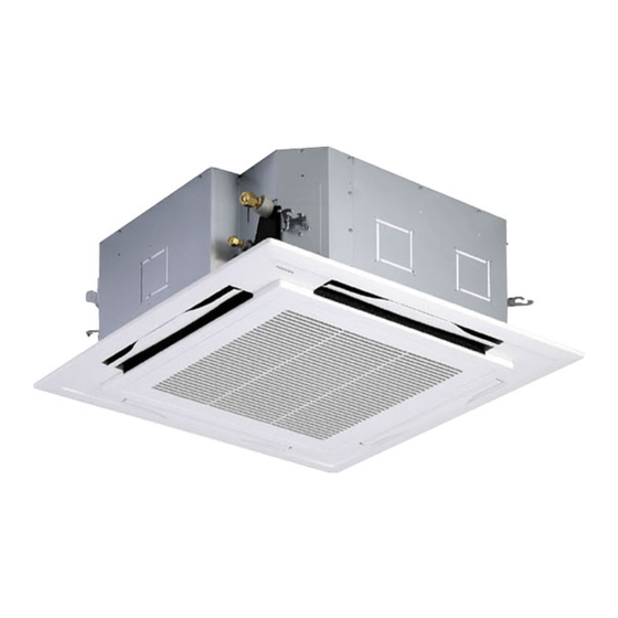
FILE NO. SVM-13010-4 SERVICE MANUAL AIR-CONDITIONER (SPLIT TYPE) INDOOR UNIT <4-way cassette type> RAV-SM564UTP-E (TR) RAV-SM804UTP-E (TR) RAV-SM1104UTP-E (TR) RAV-SM1404UTP-E (TR) RAV-SM1604UTP-E (TR) Revised on Oct. 2013... -
Page 2: Table Of Contents
Address Setup (Manual Setting from Remote Controller) ........86 9-4. Confirmation of Indoor Unit No. Position ........87 10. DETACHMENTS ......89 11. EXPLODED VIEWS AND PARTS LIST ......99 11-1. RAV-SM564UTP-E, SM804UTP-E, SM1104UTP-E, SM1404UTP-E, SM1604UTP-E ......82 11-2. RAV-SM564UTP-TR, SM804UTP-TR, SM1104UTP-TR, SM1404UTP-TR, SM1604UTP-TR ......102 – 2 –... -
Page 3: Safety Caution
The qualified service person is a person who installs, repairs, maintains, relocates and removes the air conditioners made by Toshiba Carrier Corporation. He or she has been trained to install, repair, maintain, relocate and remove the air conditioners made by Toshiba Carrier Corporation... - Page 4 FILE NO. SVM-13010 Definition of Protective Gear When the air conditioner is to be transported, installed, maintained, repaired or removed, wear protective gloves and ‘safety’ work clothing. In addition to such normal protective gear, wear the protective gear described below when undertaking the special work detailed in the table below.
-
Page 5: Warning Indications On The Air Conditioner Unit
FILE NO. SVM-13010 Warning Indications on the Air Conditioner Unit [Confirmation of warning label on the main unit] Confirm that labels are indicated on the specified positions If removing the label during parts replace, stick it as the original. WARNING WARNING ELECTRICAL SHOCK HAZARD ELECTRICAL SHOCK HAZARD... -
Page 6: Precautions For Safety
FILE NO. SVM-13010 PRECAUTIONS FOR SAFETY The manufacturer shall not assume any liability for the damage caused by not observing the description of this manual. DANGER Before carrying out the installation, maintenance, repair or removal work, be sure to set the circuit breaker for both the indoor and outdoor units to the OFF position. - Page 7 FILE NO. SVM-13010 WARNING Before starting to repair the air conditioner, read carefully through the Service Manual, and repair the air conditioner by following its instructions. Only qualified service person (*1) is allowed to repair the air conditioner. Repair of the air conditioner by unqualified person may give rise to a fire, electric shocks, injury, water leaks and / or other problems.
- Page 8 FILE NO. SVM-13010 Do not modify the products. Do not also disassemble or modify the parts. It may cause a fire, electric shock or injury. Prohibition of modification. When any of the electrical parts are to be replaced, ensure that the replacement parts satisfy the specifications given in the Service Manual (or use the parts contained on the parts list in the Service Manual).
- Page 9 FILE NO. SVM-13010 After repair work, surely assemble the disassembled parts, and connect and lead the removed wires as before. Perform the work so that the cabinet or panel does not catch the inner wires. If incorrect assembly or incorrect wire connection was done, a disaster such as a leak or fire is caused Assembly / at user’s side.
- Page 10 FILE NO. SVM-13010 When the service panel of the outdoor unit is to be opened in order for the compressor or the area around this part to be repaired immediately after the air conditioner has been shut down, set the circuit breaker to the OFF position, and then wait at least 10 minutes before opening the service panel.
-
Page 11: Declaration Of Conformity
FILE NO. SVM-13010 Declaration of Conformity Manufacturer: TOSHIBA CARRIER (THAILAND) CO., LTD. 144 / 9 Moo 5, Bangkadi Industrial Park, Tivanon Road, Amphur Muang, Pathumthani 12000, Thailand Authorized Representative / Nick Ball TCF holder: Toshiba EMEA Engineering Director Toshiba Carrier UK Ltd. -
Page 12: Specifications
FILE NO. SVM-13010 Specifications Sound power level (dBA) Weight (kg) Model Main unit (Ceiling panel) Cooling Heating RAV-SM564UTP-E (TR) 20 (4.2) RAV-SM804UTP-E (TR) 20 (4.2) RAV-SM1104UTP-E (TR) 24 (4.2) RAV-SM1404UTP-E (TR) 24 (4.2) RAV-SM1604UTP-E (TR) 24 (4.2) : Under 70 dBA... - Page 13 FILE NO. SVM-13010 • New Refrigerant (R410A) This air conditioner adopts a new HFC type refrigerant (R410A) which does not deplete the ozone layer. 1. Safety Caution Concerned to New Refrigerant The pressure of R410A is high 1.6 times of that of the former refrigerant (R22). Accompanied with change of refrigerant, the refrigerating oil has been also changed.
- Page 14 FILE NO. SVM-13010 4. Tools 1. Required Tools for R410A Mixing of different types of oil may cause a trouble such as generation of sludge, clogging of capillary, etc. Accordingly, the tools to be used are classified into the following three types. 1) Tools exclusive for R410A (Those which cannot be used for conventional refrigerant (R22)) 2) Tools exclusive for R410A, but can be also used for conventional refrigerant (R22) 3) Tools commonly used for R410A and for conventional refrigerant (R22)
-
Page 15: Construction Views (External Views)
FILE NO. SVM-13010 1. CONSTRUCTION VIEWS (EXTERNAL VIEWS) 1-1. Indoor Unit RAV-SM564UTP 1000 or more 860 to 910 Ceiling open dimension An obstacle 1000 or more The space that is necessary for equipping and service Take-in port of wiring Bottom face of ceiling Indoor unit Bottom face of ceiling Refrigerant pipe connecting port... -
Page 16: Rav-Sm804Utp
FILE NO. SVM-13010 RAV-SM804UTP 1000 or more 860 to 910 Ceiling open dimension An obstacle 1000 or more The space that is necessary for equipping and service n i l Indoor unit Bottom face of ceiling Drain upstanding size Refrigerant pipe connecting port Ø9.5 (Liquid side) Drain pipe connecting port... -
Page 17: Rav-Sm1104Utp
FILE NO. SVM-13010 RAV-SM1104UTP , RAV-SM1404UTP , RAV-SM1604UTP 1000 or more 860 to 910 Ceiling open dimension An obstacle 1000 or more The space that is necessary for equipping and service Take-in port of wiring Bottom face of ceiling Indoor unit Bottom face of ceiling Refrigerant pipe connecting port Drain pipe... -
Page 18: Systematic Refrigerating Cycle Diagram
FILE NO. SVM-13010 2. SYSTEMATIC REFRIGERATING CYCLE DIAGRAM 2-1. Indoor Unit • Single type (Combination of 1 indoor unit and 1 outdoor unit) (Indoor unit) Distributor (Strainer incorporated) TCJ sensor Strainer Air heat exchanger TC sensor Heating Cooling Refrigerant pipe Refrigerant pipe at liquid side at gas side... - Page 19 FILE NO. SVM-13010 Triple type (3 indoor units and 1 outdoor unit) Heating mode Cooling mode (Indoor unit A) (Indoor unit B) (Indoor unit C) TCJ sensor TCJ sensor TCJ sensor Distributor Distributor Distributor Strainer Strainer Strainer (with strainer) (with strainer) (with strainer) Heat...
- Page 20 FILE NO. SVM-13010 Double-twin type (4 indoor units and 1 outdoor unit) Heating mode Cooling mode (Indoor unit A) (Indoor unit B) TCJ sensor TCJ sensor Distributor Distributor (with strainer) (with strainer) Strainer Strainer Heat exchanger Heat exchanger TC sensor TC sensor Liquid-side Gas-side...
-
Page 21: Wiring Diagram
FILE NO. SVM-13010 3. WIRING DIAGRAM 3-1. Indoor Unit 3-1-1. 4-Way Cassette Type RAV-SM564UTP , RAV-SM804UTP , RAV-SM1104UTP , RAV-SM1404UTP , RAV-SM1604UTP – 21 –... -
Page 22: Specifications Of Electrical Parts
FILE NO. SVM-13010 4. SPECIFICATIONS OF ELECTRICAL PARTS 4-1. Indoor Unit RAV-SM564UTP , RAV-SM804UTP Parts name Type Specifications Fan motor (for indoor) SWF-230-60-2R Output (Rated) 60 W Thermo. sensor (TA-sensor) 310 mm 10 kΩ at 25°C Heat exchanger sensor (TCJ-sensor) Ø6 mm, 1000 mm 10 kΩ... -
Page 23: Indoor Control Circuit
FILE NO. SVM-13010 5. INDOOR CONTROL CIRCUIT 5-1. Indoor Controller Block Diagram 5-1-1. Connection of Wired (Simple) Remote Controller Wired simple Schedule Display LCD Function setup Display LCD LCD driver Display LED Key switch Function setup Key switch DC5V Remote controller DC5V Power circuit ∗3... - Page 24 FILE NO. SVM-13010 5-1-2. Connection of Wireless Remote Controller Kit Indoor unit #1 (Header) Wireless remote controller kit Receiver P .C. board Display LED Buzzer DC5V Power Remote controller circuit communication circuit (Follower) (Follower) Indoor control P .C. board (MCC-1570) DC20V Remote controller EEPROM...
- Page 25 FILE NO. SVM-13010 5-1-3. Connection of Both Wired (Simple) Remote Controller and Wireless Remote Controller Kit Indoor unit #1 (Header) Wired (simple) master remote controller Wireless remote controller kit (Max. 2 units) Schedule timer Display LED Receiver P.C. board Display Function Display setup...
-
Page 26: Control Specifications
FILE NO. SVM-13010 5-2. Control Specifications Item Outline of specifications Remarks When power 1) Distinction of outdoor unit supply is reset When the power supply is reset, the outdoors are distin- guished and the control is selected according to the distinguished result. - Page 27 FILE NO. SVM-13010 Item Outline of specifications Remarks Room temp. 2) Using the CODE No. 06, the setup temperature in heating Shift of suction control operation can be corrected. temperature in heating (Continued) operation Setup data Setup temp. correction +0°C +2°C +4°C +6°C...
- Page 28 FILE NO. SVM-13010 Item Outline of specifications Remarks Air speed selection 1) Operation with (HH), (H), (L) or [AUTO] mode is carried HH > H+ > H > L+ > out by the command from the remote controller. L > UL 2) When the air speed mode [AUTO] is selected, the air speed varies by the difference between Ta and Ts.
- Page 29 FILE NO. SVM-13010 Item Outline of specifications Remarks Air speed Standard Type 1 Type 3 Type 6 selection CODE No. Selection of high [5d] (Continued): ceiling type SW501 (1)/(2) OFF/OFF ON/OFF OFF/ON ON/ON CODE No.: HEAT COOL HEAT COOL HEAT COOL HEAT COOL [5d] or selection of high ceiling on P .C.
- Page 30 FILE NO. SVM-13010 Item Outline of specifications Remarks Cool air discharge 1) In heating operation, the indoor fan is controlled In D and E zones, the preventive control based on the detected temperature of Tc sensor or priority is given to air Tcj sensor.
- Page 31 FILE NO. SVM-13010 Item Outline of specifications Remarks High-temp. 1) The heating operation is performed as follows based on the release control detected temperature of Tc sensor or Tcj sensor. • When [M] zone is detected, the commanded frequency is However this control is decreased from the real operation frequency.
- Page 32 FILE NO. SVM-13010 Item Outline of specifications Remarks Louver control 1) Louver position setup The louver position at horizontal • When the louver position is changed, the position moves discharge position necessarily to downward discharge position once to return to at under SM80 the set position.
-
Page 33
FILE NO. SVM-13010 Item Outline of specifications Remarks Louver control <
> (Continued) • For the Swing mode, the following three types of modes are SWING/FIX selectable and settable by keeping Swing/Direction button pushed for 4 seconds or more on the remote controller. Standard (4 pieces: same phase) swing →... - Page 34 FILE NO. SVM-13010 Item Outline of specifications Remarks Louver control • If there is the locked louver in the unit, [ ] goes on the For the setting (Continued) remote controller screen. operation, refer to [How to set louver • While the following controls are performed, the louvers lock] of Installation operate even if executing the louver lock.
- Page 35 FILE NO. SVM-13010 Item Outline of specifications Remarks Central control mode 1) Setting at the centerl controller side enables to select the selection contents which can be operated on the remote controller at indoor unit side. 2) Setup contents • 64 line central controller (TCB-SC642TLE2) Display at remote [Individual]: Operated on the remote controller controller side...
- Page 36 FILE NO. SVM-13010 Item Outline of specifications Remarks DC motor 1) When the fan operation has started, positioning of the stator and the rotor are performed. (Moves slightly with tap sound) 2) The motor operates according to the command from the indoor controller.
- Page 37 FILE NO. SVM-13010 Item Outline of specifications Remarks 8°C heating/ 1) This functional is intended for the cold latitudes and performs Frost protective objective heating operation (8°C heating operation). operation 2) This function is valid only for combination with the outdoor In a group connection, units (Super Digital Inverter (SDI) 4-series outdoor units).
-
Page 38: Indoor Print Circuit Board
FILE NO. SVM-13010 5-3. Indoor Print Circuit Board– 38 –... - Page 39 FILE NO. SVM-13010 Optional Connector Specifications of Indoor P.C. Board – 39 –...
-
Page 40: Troubleshooting
FILE NO. SVM-13010 6. TROUBLESHOOTING 6-1. Summary of Troubleshooting1. Before troubleshooting 1) Required tools/instruments – • screwdrivers, spanners, radio cutting pliers, nippers, push pins for reset switch • Tester, thermometer, pressure gauge, etc. 2) Confirmation points before check a) The following operations are normal. -
Page 41
FILE NO. SVM-13010
1. Before troubleshooting 1) Required tools/instruments – • screwdrivers, spanners, radio cutting pliers, nippers, etc. • Tester, thermometer, pressure gauge, etc. 2) Confirmation points before check a) The following operations are normal. 1. Compressor does not operate. •... -
Page 42: Troubleshooting
FILE NO. SVM-13010 6-2. Troubleshooting 6-2-1. Outline of judgment The primary judgment to check whether a trouble occurred in the indoor unit or outdoor unit is carried out with the following method. Method to judge the erroneous position by flashing indication on the display part of the indoor unit (sensors of the receiving part) The indoor unit monitors the operating status of the air conditioner, and the blocked contents of self-diagnosis are displayed restricted to the following cases if a protective circuit works. - Page 43 FILE NO. SVM-13010 Lamp indication Check code Cause of trouble occurrence Operation Timer Ready ⎫ Heat exchanger sensor (TCJ) error ⎪ Heat exchanger sensor (TC) error Indoor unit sensor error ⎬ ⎪ Heat exchanger sensor (TA) error Alternate flash ⎭ Discharge temp.
- Page 44 FILE NO. SVM-13010 6-2-2. Others (Other than Check Code) Lamp indication Check code Cause of trouble occurrence Operation Timer Ready — During test run Simultaneous flash Operation Timer Ready Disagreement of cool/heat — (Automatic cool/heat setting to automatic cool/heat prohibited model, or setting of heating to cooling-only model) Alternate flash –...
- Page 45 FILE NO. SVM-13010 – 45 –...
-
Page 46: Error Mode Detected By Indoor Unit
FILE NO. SVM-13010 Error mode detected by indoor unit Operation of diagnostic function Judgment and measures Check Status of Cause of operation Condition code air conditioner 1. Check cables of remote controller and communication adapters. No communication from remote Stop Displayed when controller (including wireless) and •... -
Page 47: Error Mode Detected By Remote Controller Or Central Controller (Tcc-Link)
FILE NO. SVM-13010 Error mode detected by remote controller or central controller (TCC-LINK) Operation of diagnostic function Judgment and measures Status of Check code Cause of operation Condition air conditioner Power supply error of remote controller, Indoor EEPROM error 1. Check remote controller inter-unit wiring. No communication with master indoor unit 2. - Page 48 FILE NO. SVM-13010 6-2-4. Diagnostic Procedure for Each Check Code (Indoor Unit) Check code [E01 error] Correct inter-unit cable Is inter-unit cable of A and B normal? of remote controller Is there no disconnection or Correct connection of connector. contact error of connector on harness Check circuit wiring.
- Page 49 FILE NO. SVM-13010 [E04 error] Is group address setup of Does outdoor operate? Check CODE No. [14]. remote controller correct? Are wiring in indoor unit and Correct wiring and 1, 2, 3 inter-unit cables correct? inter-unit cables. Correct wiring of connector Are wirings of terminal blocks and terminal blocks.
- Page 50 FILE NO. SVM-13010 [E18 error] Correct inter-unit cable Is inter-unit cable of A and B normal? of remote controller. Is there no disconnection Correct connection of connector. or contact error of connector on harness from terminal block Check circuit wiring. of indoor unit? Is group control operation? Check power...
- Page 51 FILE NO. SVM-13010 [L20 error] Are wiring connections to communication lines Correct wiring connection. U3 and U4 normal? Is not the multiple same central Correct central control system address. control system addresses connected? Check central controller (including network adapter) and indoor P.C.
- Page 52 FILE NO. SVM-13010 [P10 error] Is connection of float switch connector Correct connection (Indoor control board CN34) of connector. normal? Does float switch work? Is circuit wiring normal? Check and correct wiring and wire circuit. Does drain pump work? Are connector pins 1 and 2 Is power of at drain pump unit side shorted drain pump turned on? ∗...
- Page 53 FILE NO. SVM-13010 [P12 error] Turn off the power. Is there no connection error or disconnection on connectors CN333 Correct connection and CN334 of indoor unit P.C. board of connector. (MCC-1570)? CN333 Remove connectors CN333 and CN334 of indoor unit P.C. board (MCC-1570).
- Page 54 FILE NO. SVM-13010 [P19 error] Is operation of 4-way valve normal? Are 1.3 to 1.6kΩ applied to (Check the pipe temp., etc. Replace 4-way valve coil. resistance value of 4-way valve coil ? during cooling/heating operation. Defective Check outdoor P.C. board operation. Check outdoor P.C.
- Page 55 FILE NO. SVM-13010 [F02 error] Is connection of TC sensor connector Correct connection of connector. (CN101 on Indoor P.C. board) correct? Are characteristics of Replace TC sensor. TC sensor resistance value normal? ∗ Refer to Characteristics-2. Check indoor P.C. board (MCC-1570). Defect →...
- Page 56 FILE NO. SVM-13010 [C06 error] (“1:1 model” connection interface) n i l n i l ∗1 Correct connection of connector. Is connection of connector normal? ∗1 TCC-LINK central: CN51 of “1:1 model” connection interface (TCC-LINK adapter) P.C. board (MCC-1440) and CN050 of indoor P.C.
- Page 57 FILE NO. SVM-13010 [E03 error] (Header indoor unit) [E03 error] is detected when the indoor unit cannot receive a signal from the remote controller (also central controller). Check A and B remote controllers and communication lines of the central control system U3 and U4. As communication is impossible, this check code [E03] is not displayed on the remote controller and the central controller.
-
Page 58: Temperature Sensor
FILE NO. SVM-13010 Temperature sensor Temperature – Resistance value characteristic table TA, TC, TCJ, TE, TS, TO sensors TD, TL sensors Representative value Representative value Resistance value (kΩ Ω Ω Ω Ω ) Resistance value (kΩ Ω Ω Ω Ω ) Temperature Temperature (°C) - Page 59 FILE NO. SVM-13010 Winding Resistance of Fan Motor Checking procedure Part name SWF-230-60-2R Measure the resistance value of each winding by using the tester. RAV-SM564UTP RAV-SM804UTP SWF-230-60-2R Position Resistance value 87±8.7 Ω Fan motor inside wiring diagram Black – Red 87±8.7 Ω...
-
Page 60: Replacement Of Service P.c. Board
FILE NO. SVM-13010 7. REPLACEMENT OF SERVICE P.C. BOARD 7-1. Indoort Unit - Page 61 FILE NO. SVM-13010 [1] Setting data read out from EEPROM The setting data modified on the site, other than factory-set value, stored in the EEPROM shall be read out. TEST Step 1 Push button on the remote controller simultaneously for more than 4 seconds. ∗...
- Page 62 FILE NO. SVM-13010 Setting 4-way cassette Indoor Unit model only 1. Using the set temperature buttons, set “ ” to the CODE No. (DN). 2. Using the timer time buttons, set the data. (0001) • Push button. (The setting completes if the setting data are displayed.) Connector (CN504) If the plug for short-circuit is attached on the P.C.
-
Page 63: Change The Code No. (Dn) To
FILE NO. SVM-13010 Step 4 Write the on-site setting data to the EEPROM, such as address setting, etc. Perform the steps 1 and 2 above again. Step 5 Change the CODE No. (DN) to “ ” by pushing buttons for the temperature setting. (this is the setting for the filter sign lighting time.) Step 6 Check the setting data displayed at this time with the setting data put down in [1]. -
Page 64: Type
FILE NO. SVM-13010 Table 1. Setting data (CODE No. table (example)) Item Setting data Factory-set value Filter sign lighting time Depending on Type Filter pollution leve 0000: standard Central control address 0099: Not determined 0002: +2°C Heating suction temperature shift (flooring installation type: 0) Cooling only 0000: Heat pump... -
Page 65: Setup At Local Site And Others
FILE NO. SVM-13010 8. SETUP AT LOCAL SITE AND OTHERS 8-1. Indoor Unit 8-1-1. Test Run Setup on Remote ControllerTEST 1. When pushing button on the remote controller for 4 seconds or more, “TEST” is displayed on LC display. ON / OFF Then push button. - Page 66 FILE NO. SVM-13010 8-1-2. Forced Defrost Setup of Remote Controller (For wired remote controller only) (Preparation in advance) TEST Push buttons simultaneously for 4 seconds or more on the remote controller. (Push buttons while the air conditioner stops.) The first displayed unit No. is the master indoor unit address in the group control. UNIT Every pushing button, the indoor unit No.
-
Page 67
FILE NO. SVM-13010 8-1-4. Function Selection Setup
Perform setting while the air conditioner stops. TEST Push buttons simultaneously for 4 seconds or more. The first displayed unit No. is the master indoor unit address in the group control. In this time, fan and louver of the selected indoor unit operate. UNIT LOUVER Every pushing button (button at left side), the indoor unit No. - Page 68 FILE NO. SVM-13010 Function selection CODE No. (DN) list Item Contents At shipment from factory Filter sign lighting time 0002: 2500H 0003: 5000H According to type 0004: 10000H 0005: Clogging sensor used 0000: Standard Filter stain level 0000: Standard 0001: Heavy stain (Half of standard time) 0001: No.1 unit 0064: No.64 unit Central control address...
- Page 69 FILE NO. SVM-13010 Item Contents At shipment from factory Set when compressor-ON time is 10 to 60 minutes. Self-clean operation time 0002: 1 hour When ON-time is 60 minutes or more, the double of this operation time setting is set. Selection of louver horizontal discharge 0000: Smudging-less setting 0000: Smudging-...
-
Page 70
FILE NO. SVM-13010 8-1-5. Wiring and Setting of Remote Controller Control 2-remote controller control
(Controlled by 2 remote controllers) How to set wired remote controller This control is to operate 1 or multiple indoor units as sub remote controller are operated by 2 remote controllers. -
Page 71
FILE NO. SVM-13010
Remote controller address (A-B selection) setting • When two or more signal receiving units are installed in a room, a unique address can be set for each signal receiving unit to prevent interference. • Address (A-B selection) must be changed on both signal receiving unit and wireless remote controller. - Page 72 FILE NO. SVM-13010 Wireless remote controller (A-B selection) Using 2 wireless remote controllers for the respec- tive air conditioners, when the 2 air conditioners are closely installed. Wireless remote controller B setup 1. Start the air conditioner. 2. Point the wireless remote controller at the indoor unit.
-
Page 73
FILE NO. SVM-13010 8-1-6. Monitor Function of Remote Controller Switch Calling of sensor temperature display
Each data of the remote controller, indoor unit and outdoor unit can be understood by calling the service monitor mode from the remote controller. ... -
Page 74
FILE NO. SVM-13010 Calling of error history
The error contents in the past can be called. TEST Push buttons simultaneously for 4 seconds or more to call the service check mode. Service Check goes on, the CODE No. is displayed, and TEMP. -
Page 75
FILE NO. SVM-13010 Indoor unit power-ON sequence • The unit without power feed waits entirely → Waiting status is released by system start Power ON • Reboot when power is fed on the way
... -
Page 76: Setup At Local Site / Others
FILE NO. SVM-13010 8-2. Setup at Local Site / Others Model name: TCB-PCNT30TLE2 8-2-1. 1:1 Model Connection Interface (TCC-LINK adapter) 1. Function This model is an optional P.C. board to connect the indoor unit to 1:1 model connection interface. 2. Microprocessor block diagram Indoor unit Central controller 1:1 model connection interface... -
Page 77: Wiring Specifications
FILE NO. SVM-13010 4. Wiring Specifications • Use 2-core with no polar wire. No. of wires Size • Match the length of wire to wire length of the central control system. If mixed in the SMMS system, the wire length is Up to 1000m: twisted wire 1.25mm Up to 2000m: twisted wire 2.0mm lengthened with all indoor/outdoor inter-unit wire length at side. -
Page 78: How To Set Up Central Control Address Number
FILE NO. SVM-13010 6. External view of P.C. board assembly Terminator (SW01) 7. Address setup In addition to set up the central control address, it is necessary to change the indoor unit number. (Line/Indoor/Group address). For details, refer to 1:1 model connection interface Installation Manual. 8-3. -
Page 79
FILE NO. SVM-13010 How to confirm the central control address (New function for AMT32E remote controller) How to confirm the central control address (New function for AMT32E remote controller)
It can be confirmed even during operation or stopping. It can be confirmed even during operation or stopping. UNIT LOUVER UNIT LOUVER Push... -
Page 80: How To Set Up Type Of Swing
FILE NO. SVM-13010 ∗ Dual swing 8-4. How to set up type of swing (Recommended for heating operation) SWING/FIX • The adjoined louvers repeat horizontal Push for 4 seconds or more during stop of discharge/Downward discharge alternately the operation. to clear irregularity of the temperature in •... -
Page 81: How To Set Louver Lock (Louver Fix)
FILE NO. SVM-13010 8-5. How to set louver lock (Louver fix) Refrigerant pipe UNIT LOUVER Push (At the right side of the button) for 4 seconds or more during stop of the operation. Electric parts box • flashes. UNIT LOUVER Push (At the left side of the button) and Drain pipe... -
Page 82: Address Setup
FILE NO. SVM-13010 9. ADDRESS SETUP 9-1. Address Setup When an outdoor unit and an indoor unit are connected and they are twin-triple, or when an outdoor unit is connected to each indoor unit respectively in the group operation even if multiple refrigerant lines are provided, the automatic address setup completes with power-ON of the outdoor unit. -
Page 83: Address Setup & Group Control
FILE NO. SVM-13010 9-2. Address Setup & Group ControlIndoor unit No. : N – n = Outdoor unit line address N (Max. 30) – Indoor unit address n (Max. 64) Group address : 0 = Single (Not group control) 1 = Header unit in group control 2 = Follower unit in group control Header unit (= 1) : The representative of multiple indoor units in group operation sends/receives signals to/... - Page 84 FILE NO. SVM-13010 4. Single group operation • Each indoor unit controls the outdoor unit individually. Header/Sub Header/Sub Header/Master Header/Sub Header/Sub 5. Multiple groups operation (Manual address setting) Header/Sub Header/Sub Follower/Sub Header/Master Follower/Sub Follower/Sub • Master unit: The master unit receives the indoor unit data (thermo status) of the sub (Without identical line address &...
- Page 85 FILE NO. SVM-13010 9-2-2. Automatic Address Example from Unset Address (No miswiring) 1. Standard (One outdoor unit) (1-1) (1-2) (1-1) (1-2) (1-3) Individual Header/Master Follower/Sub Header/Sub Follower/Master Follower/Sub (Header/Master) Only turning on source power supply (Automatic completion) 2. Group operation (Multiple outdoor units = Multiple indoor units with serial communication only, without twin) Header/Sub Header/Sub...
-
Page 86: Address Setup (Manual Setting From Remote Controller)
FILE NO. SVM-13010 9-3. Address Setup (Manual Setting from Remote Controller) In case that addresses of the indoor units will be (Example of 2-lines wiring) (Real line: Wiring, Broken line: Refrigerant pipe) determined prior to piping work after wiring work Outdoor Outdoor •... -
Page 87: Confirmation Of Indoor Unit No. Position
FILE NO. SVM-13010 9-4. Confirmation of Indoor Unit No. Position 1. To know the indoor unit addresses though position of the indoor unit body is recognized • In case of individual operation (Wired remote controller : indoor unit = 1 : 1) (Follow to the procedure during operation)... -
Page 88
FILE NO. SVM-13010
Aiming in environmental preservation, it is strictly recommended to clean and maintain the indoor/outdoor units of the operating air conditioning system regularly to secure effective operation of the air conditioner. It is also recommended to maintain the units once a year regularly when operating the air conditioner for a long time. -
Page 89: Detachments
FILE NO. SVM-13010 10. DETACHMENTS 10-1. 4-Way Cassette Type RAV-SM564UTP , RAV-SM804UTP , RAV-SM1104UTP , RAV-SM1404UTP , RAV-SM1604UTP Part name Procedure Remarks Suction grille Suction grille Knobs of the XCAUTIONX suction grille hook Be sure to put on the gloves at disassembling work;... - Page 90 FILE NO. SVM-13010 Part name Procedure Remarks Electric parts cover (Continued) 1. Detachment Adjust corner cap Adjust corner cap 1) Pull knob of the adjust corner cap to the arrow direction, remove strap of the adjust corner cap from pin of the panel and then remove all the 4 corners of the cap.
- Page 91 FILE NO. SVM-13010 Part name Procedure Remarks 1. Detachment Ceiling panel Clamp 1) Carry out works of item 1 of and item 1 of 3 . Louv Louver motor wir Louver motor wiring er motor wiring 2) Remove the flap connector (CN510, White, 20P) connected to the control P .C.
- Page 92 FILE NO. SVM-13010 Part name Procedure Remarks 1. Detachment Control Clamp P .C. board 1) Carry out work of item 1 of 2) Remove connectors which are connected from the control P .C. board to the other parts and then remove wiring from the clamp.
- Page 93 FILE NO. SVM-13010 Part name Procedure Remarks 1. Detachment Drain cap Drain cap (outside) 1) Carry out work of item 1 of 2) Loosen screws (3 positions) fixing the drain cap (outside) and then turn the drain cap to the arrow mark direction to remove it. CLOSE CLOSE CLOSE...
- Page 94 FILE NO. SVM-13010-2 Part name Procedure Remarks 1. Detachment Fan motor Fixing screw A 1) Carry out work of item 1 of 2) Remove connectors which are connected from the control P .C. board to the other parts and then remove each wiring from the clamp.
- Page 95 FILE NO. SVM-13010-2 Part name Procedure Remarks 2. Attachment Fan motor M6 nut (Continued) 2) Fix the fan motor lead, TC sensor and TCJ sensor with the clamp of the bell mouth. 3) Mount the electric parts box with the fixing screws A and B.
- Page 96 FILE NO. SVM-13010 Part name Procedure Remarks 1. Detachment Drain pump Fixing screw A 1) Carry out works of item 1 of and item 1 of 6 . 2) Remove the drain pump connector Drain por Drain port ain port (CN504, White, 2P) connected to the control P .C.
- Page 97 FILE NO. SVM-13010 Part name Procedure Remarks 1. Detachment Float switch assembly 1) Carry out works of item 1 of and works from 1) to 5). Float s Float switch assemb Float switch assembly witch assembly 2) Remove the fixing screw and then remove the float switch assembly.
- Page 98 FILE NO. SVM-13010-2 Part name Procedure Remarks 1. Detachment Heat exchanger 1) Recover the refrigerant gas. 2) Carry out work of item 1 of 3) Remove refrigerant pipe at indoor unit side. 4) Remove the fixing screws and then remove the piping cover. (Ø4 × 10, 3 pcs.) 5) Remove the drain hose from the drain pump and remove the fixing screws to Fixing screws (Ø4 ×10)
-
Page 99: Exploded Views And Parts List
FILE NO. SVM-13010 11. EXPLODED VIEWS AND PARTS LIST 11-1. RAV-SM564UTP-E, SM804UTP-E, SM1104UTP-E, SM1404UTP-E, SM1604UTP-E – 99 –... - Page 100 FILE NO. SVM-13010-4 RAV-SM Ref.No. Part No. Description 564UTP-E 804UTP-E 1104UTP-E 1404UTP-E 1604UTP-E 43T20335 FAN, ASSY TURB 43T20334 FAN, ASSY TURB 43T44493 REFRIGERATION CYCLE ASSY 43T44494 REFRIGERATION CYCLE ASSY 43T44495 REFRIGERATION CYCLE ASSY 43T22322 BELL MOUTH 43T72311 PAN ASSY, DRAIN 43T70315 HOSE, DRAIN 43T83307...
- Page 101 FILE NO. SVM-13010 Electric parts RAV-SM Ref.No. Part No. Description 564UTP-E 804UTP-E 1104UTP-E 1404UTP-E 1604UTP-E SERVICE-SENSOR, ϕ6 43T60432 43T50476 SERVICE-SENSOR, TA 43T60427 SERV-TERMINAL, 3P, 20A 43T60434 TERMINAL BLOCK, 2P 43T6V364 ASM-PCB, MCC-1570 – 101 –...
-
Page 102: Rav-Sm564Utp-Tr, Sm804Utp-Tr, Sm1104Utp-Tr, Sm1404Utp-Tr, Sm1604Utp-Tr
FILE NO. SVM-13010 11-2. RAV- SM564UTP-TR, SM804UTP-TR, SM1104UTP-TR, SM1404UTP-TR, SM1604UTP-TR – 102 –... - Page 103 FILE NO. SVM-13010-4 RAV-SM Ref.No. Part No. Description 564UTP-TR 804UTP-TR 1104UTP-TR 1404UTP-TR 1604UTP-TR 43T20335 FAN, ASSY TURB 43T20334 FAN, ASSY TURB 43T44493 REFRIGERATION CYCLE ASSY 43T44494 REFRIGERATION CYCLE ASSY 43T44495 REFRIGERATION CYCLE ASSY 43T22322 BELL MOUTH 43T72311 PAN ASSY, DRAIN 43T70315 HOSE, DRAIN 43T83307 BAND, HOSE 43T63348 CLAMP, DOWN...
- Page 104 FILE NO. SVM-13010 Electric parts RAV-SM Ref.No. Part No. Description 564UTP-TR 804UTP-TR 1104UTP-TR 1404UTP-TR 1604UTP-TR 43T60432 SERVICE-SENSOR, ϕ6 43T50476 SERVICE-SENSOR, TA 43T60427 SERV-TERMINAL, 3P, 20A 43T60434 TERMINAL BLOCK, 2P 43T6V364 ASM-PCB, MCC-1570 – 104 –...
- Page 105 FILE NO. SVM-13010 RBC-U31PG (W, WS)-E, RBC-U31PGS (W, WS)-E 308, 309 306, 307, 323, 324 310, 311 Model Name RBC- Location Part No. Description U31PG (W)-E U31PG (WS)-E U31PGS (W)-E U31PGS (WS)-E 43409207 Grille, Air Inlet 43480017 Air Filter, ABS + PPNET 4302D003 Motor, Louver, MP24Z3N 43407145...
- Page 106 FILE NO. SVM-13010 WARNINGS ON REFRIGERANT LEAKAGE Check of Concentration Limit The room in which the air conditioner is to be installed requires a design that in the event of refrigerant gas leaking out, its concentration will not exceed a set limit. The refrigerant R410A which is used in the air conditioner is safe, without the toxicity or combustibility of ammonia, and is not restricted by laws to be imposed which protect the ozone layer.
- Page 107 TOSHIBA CARRIER (THAILAND) CO.,LTD. 144/9 MOO 5, BANGKADI INDUSTRIAL PARK, TIVANON ROAD, TAMBOL BANGKADI, AMPHUR MUANG, PATHUMTHANI 12000, THAILAND.