Table of Contents
SERVICE MANUAL
TECHNICAL INFORMATION
FOR SERVICE PERSONNEL ONLY
RAK-18NH6AS
RAK-18NH6A
RAK-25NH6A
RAK-35NH6A
RAK-50NH6A
NOTE:
This manual describes only points that differ from
RAF-25, 35NH5, RAD-25, 35NH5, RAI-25, 35NH5 and
RAM-55QH5 (PM No. 0312E) for items not described
in this manual.
SPECIFICATIONS
TYPE
MODEL
POWER SOURCE
TOTAL INPUT
TOTAL AMPERES
COOLING
CAPACITY
TOTAL INPUT
TOTAL AMPERES
HEATING
CAPACITY
DIMENSIONS
(mm)
NET WEIGHT
SPECIFICATIONS AND PARTS ARE SUBJECT TO CHANGE FOR IMPROVEMENT
ROOM AIR CONDITIONER
APRIL 2011
RAK-18NH6AS
(W)
(A)
(kW)
(B.T.U./h)
(W)
(A)
(kW)
(B.T.U./h)
W
H
D
(kg)
9.0
INDOOR UNIT
Refrigeration & Air-Conditioning Division
PM
RAK-18NH6AS
RAK-18NH6A
RAK-25NH6A
RAK-35NH6A
RAK-50NH6A
REFER TO THE FOUNDATION MANUAL
SPECIFICATIONS ------------------------------------------------------ 5
HOW TO USE ---------------------------------------------------------11
CONSTRUCTION AND DIMENSIONAL DIAGRAM ---------33
MAIN PARTS COMPONENT --------------------------------------34
WIRING DIAGRAM ---------------------------------------------------35
CIRCUIT DIAGRAM --------------------------------------------------37
PRINTED WIRING BOARD LOCATION DIAGRAM --------39
BLOCK DIAGRAM ----------------------------------------------------43
BASIC MODE ----------------------------------------------------------45
REFRIGERATING CYCLE DIAGRAM---------------------------59
AUTO SWING FUNCTION -----------------------------------------61
DESCRIPTION OF MAIN CIRCUIT OPERATION -----------62
SERVICE CALL Q & A ----------------------------------------------67
PARTS LIST AND DIAGRAM --------------------------------------77
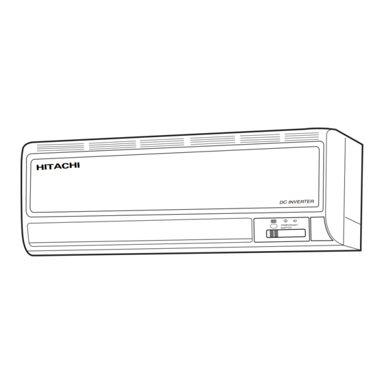
DC INVERTER (WALL TYPE)
INDOOR UNIT
RAK-18NH6A
RAK-25NH6A
1ø 50/60Hz, 220-240V
REFER TO THE SPECIFICATION (OUTDOOR)
780
280
220
9.0
9.5
NO. 0489E
CONTENTS
RAK-35NH6A
RAK-50NH6A
9.5
9.5
Table of Contents

Related Manuals for Hitachi RAK-18NH6AS


Summary of Contents for Hitachi RAK-18NH6AS
-
Page 1: Table Of Contents
NO. 0489E RAK-18NH6AS RAK-18NH6A SERVICE MANUAL RAK-25NH6A RAK-35NH6A TECHNICAL INFORMATION RAK-50NH6A FOR SERVICE PERSONNEL ONLY REFER TO THE FOUNDATION MANUAL CONTENTS SPECIFICATIONS ------------------------------------------------------ 5 HOW TO USE ---------------------------------------------------------11 CONSTRUCTION AND DIMENSIONAL DIAGRAM ---------33 MAIN PARTS COMPONENT --------------------------------------34 RAK-18NH6AS WIRING DIAGRAM ---------------------------------------------------35... - Page 2 SAFETY DURING REPAIR WORK 1. In order to disassemble and repair the unit in question, be sure to disconnect the power cord plug from the power outlet before starting the work. 2. If it is necessary to replace any parts, they should be replaced with respective genuine parts for the unit, and the replacement must be ef- fected in correct manner according to the instructions in the Service Manual of the unit.
- Page 3 WORKING STANDARDS FOR PREVENTING BREAKAGE OF SEMICONDUCTORS 1. Scope The standards provide for items to be generally observed in carrying and handling semiconductors in rela- tive manufacturers during maintenance and handling thereof. (They apply the same to handling of abnormal goods such as rejected goods being returned).
- Page 4 (6) Use a three wire type soldering iron including a grounding wire. Metal plate (of aluminium, stainless steel, etc.) Working table Resistor of 1 M (1/2W) Staple Earth wire Bare copper wire (for body earth) Fig. 3. Grounding of the working table Soldering iron Grounding wire...
- Page 5 CAUTION In quiet operation or stopping the running, slight fl owing noise of refrigerant in the refrigerating cycle is heard occasionally, but this noise is not abnormal for the operation. When it thunders near by, it is recommend to stop the operation and to disconnect the power cord plug from the power outlet for safety.
-
Page 6: Specifications
SPECIFICATIONS RAK-18NH6AS, RAK-18NH6A, RAK-25NH6A, RAK-35NH6A, RAK-50NH6A MODEL FAN MOTOR FAN MOTOR CAPACITOR FAN MOTOR PROTECTOR – COMPRESSOR COMPRESSOR MOTOR CAPACITOR OVERLOAD PROTECTOR OVERHEAT PROTECTOR FUSE (for MICROPROCESSOR) POWER RELAY POWER SWITCH TEMPORARY SWITCH SERVICE SWITCH TRANSFORMER VARISTOR NOISE SUPPRESSOR YES(IC) - Page 7 – 6 –...
- Page 8 – 7 –...
- Page 9 – 8 –...
- Page 10 – 9 –...
- Page 11 SWITCH SETTING TO SELECT 1.8 kW OR 1.2 kW CAPACITY CAUTION Before setting the switch, make sure to turn OFF power supply and then set the position of the switch otherwise will cause damage to the Main PCB. SWITCH POSITION CAPACITY SELECTION 1.2kW 1.8kW...
- Page 12 For maximum performance, it is recommended to replace it every 1 year depending on application requirements. MODEL NAME AND DIMENSIONS MODEL WIDTH (mm) HEIGHT (mm) DEPTH (mm) RAK-18NH6AS/RAK-18NH6A/RAK-25NH6A/ RAK-35NH6A/RAK-50NH6A – 11 –...
- Page 13 INDOOR UNIT INDICATORS FILTER LAMP When the device is operated for a total of about 200 hours, the FILTER lamp lights to indicate that it is time to clean the lter. OPERATION LAMP This lamp lights during operation. TEMPORARY The OPERATION LAMP ...
- Page 14 Note Avoid to use the room air conditioner for cooling operation when the outside temperature is below 21°C (70°F). The recommended maximum and minimum operating temperatures of the hot and cold sides should be as below: Cooling Heating Minimum Maximum Minimum Maximum Dry bulb °C...
-
Page 15: Safety Precaution
SAFETY PRECAUTION Please read the “Safety Precaution” carefully before operating the unit to ensure correct usage of the unit. Pay special attention to signs of “ Warning” and “ Caution”. The “Warning” section contains matters which, if not observed strictly, may cause death or serious injury. The “Caution” section contains matters which may result in serious consequences if not observed properly. - Page 16 PRECAUTIONS DURING OPERATION The product shall be operated under the manufacturer specification and not for any other intended use. Do not attempt to operate the unit with wet hands, this could cause fatal accident. When operating the unit with burning equipments, regularly ventilate the room to avoid oxygen insufficiency.
-
Page 17: Names And Functions Of Remote Control Unit
NAMES AND FUNCTIONS OF REMOTE CONTROL UNIT REMOTE CONTROLLER This controls the operation of the indoor unit. The range of control is about 7 meters. If indoor lighting is controlled electronically, the range of control may be shorter. This unit can be fixed on a wall using the fixture provided. Before fixing it, make sure the indoor unit can be controlled from the remote controller. Handle the remote controller with care. -
Page 18: Automatic Operation
VARIOUS FUNCTIONS n Auto Restart Control If there is a power failure, operation will be automatically restarted when the power is resumed with previous operation mode and airflow direction. (As the operation is not stopped by remote controller.) If you intend not to continue the operation when the power is resumed, switch off the power supply. When you switch on the circuit breaker, the operation will be automatically restarted with previous operation mode and airflow direction. -
Page 19: Heating Operation
HEATING OPERATION Use the device for heating when the outdoor temperature is under 21°C. When it is too warm (over 21°C), the heating function may not work in order to protect the device. In order to keep reliability of the device, please use this device above -15°C of the outdoor temperature. -
Page 20: Dehumidifying Operation
DEHUMIDIFYING OPERATION Use the device for dehumidifying when the room temperature is over 16°C. When it is under 15°C, the dehumidifying function will not work. Press the FUNCTION selector so that the display indicates (DEHUMIDIFY). The FAN SPEED is set at LOW or SILENT. Set the desired room temperature with the TEMPERATURE button (the display indicates the setting). -
Page 21: Cooling Operation
COOLING OPERATION Use the device for cooling when the outdoor temperature is –21°C~ 43°C. If in doors humidity is very high (80%), some dew may form on the air outlet grille of the indoor unit. Press the FUNCTION selector so that the display indicates (COOL). -
Page 22: Fan Operation
FAN OPERATION You can use the device simply as an air circulator. Use this function to dry the interior of the indoor unit at the end of summer. Press the FUNCTION selector so that the display indicates (FAN). Press the (FAN SPEED) button. (HI) : The strongest air blow. -
Page 23: How To Set The Timer
HOW TO SET THE TIMER Time Set the (TIME) button. After you change the batteries; TIME OFF TIMER ON TIMER OFF-Timer Press the (OFF-TIMER) button. The (OFF) mark blinks on the display. - Page 24 Set the current time with the Press the (TIME) button again. Press the TIMER control button. The time indication starts lighting instead of flashing. (TIME) button. The time indication will disappear automatically in 10 second. To check the current time setting, press the (TIME) button twice.
-
Page 25: How To Set The Sleep Timer
HOW TO SET THE SLEEP TIMER Set the current time at first if it is not set before (see the pages for setting the current time). Press the (SLEEP) button, and the display changes as shown below. Mode Indication 1 hour 2 hours 3 hours 7 hours Sleep timer Sleep timer off Sleep Timer: The device will continue working for the designated... -
Page 26: Circuit Breaker
HOW TO EXCHANGE THE BATTERIES IN THE REMOTE CONTROLLER Remove the cover as shown in the fi gure and take out the old batteries. Install the new batteries. The direction of the batteries should match the marks in the case. CAUTION 1. - Page 27 THE IDEAL WAYS OF OPERATION Suitable Room Temperature Install curtain or blinds Warning It is possible Freezing temperature to reduce heat is bad for health and entering the a waste of electric room through power. windows. Ventilation Effective Usage Of Timer At night, please use the “OFF or ON timer Caution operation mode”, together with your wake up...
- Page 28 FOR USER’S INFORMATION The Air Conditioner And The Heat Source In The Room Caution If the amount of heat in the room is above the cooling capability of the air conditioner (for example: more people entering the room, using heating equipments and etc.), the preset room temperature cannot be achieved.
-
Page 29: Attaching The Air Cleansing Filters
ATTACHING THE AIR CLEANSING FILTERS CAUTION Cleaning and maintenance must be carried out only by qualifi ed service personal. Before cleaning, stop operation and switch off the power supply. Open the front panel. ● Pull up the front panel by holding it at both sides with both hands. - Page 30 MAINTENANCE CAUTION Cleaning and maintenance must be carried out only by qualifi ed service personal. Before cleaning, stop operation and switch off the power supply. AIR FILTER Clean the air fi lter, as it removes dust inside the room. In case the air fi lter is full of dust, the air fl ow will decrease and the cooling capacity will be reduced.
- Page 31 Washable Front Panel ● Remove the front panel and wash with clean water. Wash it with a soft sponge. After using neutral detergent, wash thoroughly with clean water. ● When front panel is not removed, wipe it with a soft dry cloth. Wipe the remote controller thoroughly with a soft dry cloth.
- Page 32 CAUTION Cleaning and maintenance must be carried out only by qualifi ed service personal. Before cleaning, stop operation and switch off the power supply. MAINTENANCE AT BEGINNING OF LONG OFF PERIOD Running the unit setting the operation mode to ● (FAN) and the fan speed to HI for about half a day on a fi...
- Page 33 AFTER SALE SERVICE AND WARRANTY WHEN ASKING FOR SERVICE, CHECK THE FOLLOWING POINTS. CONDITION CHECK THE FOLLOWING POINTS If the remote controller is ● Do the batteries need replacement? not transmitting a signal. ● Is the polarity of the inserted batteries correct? Remote controller dis- play is dim or blank.) ●...
- Page 34 – 33 –...
-
Page 35: Main Parts Component
MAIN PARTS COMPONENT THERMOSTAT Thermostat Specifi cations MODEL RAK-18NH6AS, RAK-18NH6A, RAK-25NH6A, RAK-35NH6A, RAK-50NH6A THERMOSTAT MODEL OPERATION MODE COOL HEAT 16.7 (62.1) 20.0 (68.0) INDICATION 16.0 (60.8) 20.7 (69.3) TEMPERATURE 24.7 (76.5) 28.0 (82.4) INDICATION °C (°F) 24.0 (75.2) 28.7 (83.7) 32.7 (90.9) -
Page 36: Wiring Diagram
WIRING DIAGRAM MODEL RAK-18NH6AS, RAK-18NH6A, RAK-25NH6A, RAK-35NH6A, RAK-50NH6A INDOOR UNIT – 35 –... -
Page 37: Circuit Diagram
CIRCUIT DIAGRAM Remote Control WIRELESS Output TRANSMITION Input OUTPUT Door open Off timer On timer Reservation Cancel Door shut Sleep – – – Door open Start/stop Time setting Hour up Hour down Door shut Start/stop Fan speed selection Temperature up Temperature down Door open Operation mode select... -
Page 38: Printed Wiring Board Location Diagram
PRINTED WIRING BOARD LOCATION DIAGRAM MODEL RAK-18NH6AS, RAK-18NH6A – 39 –... - Page 39 CIRCUIT DIAGRAM MODEL RAK-18NH6A, RAK-25NH6A, RAK-35NH6A, RAK-50NH6A – 41 –...
- Page 40 – 43 –...
- Page 41 Notes: Combination of operations: 1. Refer to the PWRITE-ZU data for the constants expressed by capital alphabet letters in When operation mode is selected: During automatic operation: One unit Other unit the drawing. You cannot operate the indoor units in the following combinations. When heating operation is automatically selected for the fi...
- Page 42 MODEL RAK-25NH6A RAK-35NH6A RAK-50NH6A RAK-18NH6AS RAK-18NH6A PROM REQUIRED VALUE REQUIRED VALUE REQUIRED VALUE REQUIRED VALUE REQUIRED VALUE LABEL NAME OF UNIT SIDE OF UNIT SIDE OF UNIT SIDE OF UNIT SIDE OF UNIT SIDE RTOTSA 0°C 0°C 0°C 0°C WMAX_M...
- Page 43 – 49 –...
- Page 44 – 51 –...
- Page 45 Dehumidifying Dehumidifying Sleep Operation – 53 –...
- Page 46 – 55 –...
- Page 47 – 57 –...
- Page 48 – 59 –...
- Page 49 – 60 –...
- Page 50 – 61 –...
- Page 51 – 62 –...
- Page 52 – 63 –...
- Page 53 – 64 –...
- Page 54 – 65 –...
- Page 55 8. Initial Setting Circuit (IC401) – For RAK-18NH6AS only When power is supplied, the microcomputer reads the data in IC401 and IC402 (E PROM) and sets the ● preheating activation value and the rating and maximum speed of the compressor, etc. to their initial values.
- Page 56 MODEL RAK-18NH6AS, RAK-18NH6A, RAK-25NH6A, RAK-35NH6A, RAK-50NH6A – 67 –...
- Page 57 – 68 –...
- Page 58 – 69 –...
- Page 59 RAK-18NH6AS, RAK-18NH6A, RAK-25NH6A, RAK-35NH6A, RAK-50NH6A RAK-18NH6AS, RAK-18NH6A, RAK-25NH6A, RAK-35NH6A, RAK-50NH6A 2 sec. 2 sec. 2 sec. 2 sec. 2 sec. 2 sec. 2 sec. 0.35 0.35 connecting cable – 70 –...
- Page 60 – 71 –...
- Page 61 – 72 –...
- Page 62 – 73 –...
- Page 63 – 74 –...
- Page 64 RAK-18NH6AS, RAK-18NH6A, RAK-25NH6A, RAK-35NH6A, RAK-50NH6A – 75 –...
- Page 65 – 76 –...
-
Page 66: Parts List And Diagram
PARTS LIST AND DIAGRAM INDOOR UNIT MODEL: RAK-18NH6AS, RAK-18NH6A, RAK-25NH6A, RAK-35NH6A, RAK-50NH6A – 77 –... - Page 67 MODEL RAK-18NH6AS PART N0. Q’TY / UNIT PARTS NAME RAK-18NH6AS PMRAS-07GH4 CABINET PMRAS-25YH4 FAN MOTOR PMRAS-260GA TANGENTIAL AIR FLOW FAN PMRAS-25YH4 FAN SUPPORT ASSEMBLY PMRAS-25YH4 FAN COVER PMRAS-25YH4 FAN MOTOR SUPPORT PMRAS-07GH4 CYCLE ASSY PMRAK-25NH6 PIPE SUPPORT PMRAS-25YH4 SPRING PMRAS-25YH4...
- Page 68 MODEL RAK-18NH6A PART N0. Q’TY / UNIT PARTS NAME RAK-18NH6A PMRAS-07GH4 CABINET PMRAS-25YH4 FAN MOTOR PMRAS-260GA TANGENTIAL AIR FLOW FAN PMRAS-25YH4 FAN SUPPORT ASSEMBLY PMRAS-25YH4 FAN COVER PMRAS-25YH4 FAN MOTOR SUPPORT PMRAS-07GH4 CYCLE ASSY PMRAK-25NH6 PIPE SUPPORT PMRAS-25YH4 SPRING PMRAS-25YH4 TERMINAL BOARD (2P) PMRAS-260GHA THERMISTOR ASSEMBLY...
- Page 69 MODEL RAK-25NH6A PART N0. Q’TY / UNIT PARTS NAME RAK-25NH6A PMRAS-07GH4 CABINET PMRAS-25YH4 FAN MOTOR PMRAS-260GA TANGENTIAL AIR FLOW FAN PMRAS-25YH4 FAN SUPPORT ASSEMBLY PMRAS-25YH4 FAN COVER PMRAS-25YH4 FAN MOTOR SUPPORT PMRAK-25NH5 CYCLE ASSY PMRAK-25NH6 PIPE SUPPORT PMRAS-25YH4 SPRING PMRAS-25YH4 TERMINAL BOARD (2P) PMRAS-260GHA THERMISTOR ASSEMBLY...
- Page 70 MODEL RAK-35NH6A PART N0. Q’TY / UNIT PARTS NAME RAK-35NH6A PMRAS-07GH4 CABINET PMRAS-25YH4 FAN MOTOR PMRAS-260GA TANGENTIAL AIR FLOW FAN PMRAS-25YH4 FAN SUPPORT ASSEMBLY PMRAS-25YH4 FAN COVER PMRAS-25YH4 FAN MOTOR SUPPORT PMRAK-25NH5 CYCLE ASSY PMRAK-25NH6 PIPE SUPPORT PMRAS-25YH4 SPRING PMRAS-25YH4 TERMINAL BOARD (2P) PMRAS-260GHA THERMISTOR ASSEMBLY...
- Page 71 MODEL RAK-50NH6A PART N0. Q’TY / UNIT PARTS NAME RAK-50NH6A PMRAS-07GH4 CABINET PMRAS-25YH4 FAN MOTOR PMRAS-260GA TANGENTIAL AIR FLOW FAN PMRAS-25YH4 FAN SUPPORT ASSEMBLY PMRAS-25YH4 FAN COVER PMRAS-25YH4 FAN MOTOR SUPPORT PMRAS-19SH4 CYCLE ASSY PMRAK-25NH6 PIPE SUPPORT PMRAS-25YH4 SPRING PMRAS-25YH4 TERMINAL BOARD (2P) PMRAS-260GHA THERMISTOR ASSEMBLY...
- Page 72 HITACHI RAK-18NH6AS RAK-18NH6A RAK-25NH6A PM NO. 0489E RAK-35NH6A RAK-50NH6A Printed in Malaysia...