Cisco TelePresence MX700 Installation Manual
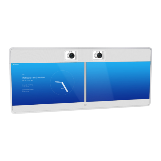
Dual camera mounted on the wall
Hide thumbs
Also See for TelePresence MX700:
- Reference manual (241 pages) ,
- Administrator's manual (141 pages) ,
- Installation manual (32 pages)
Table of Contents
Quick Links
See also:
Administrator's Manual, Installation Manual
Table of Contents

Related Manuals for Cisco TelePresence MX700


Summary of Contents for Cisco TelePresence MX700
-
Page 1: Installation Guide
Installation guide for Cisco TelePresence MX700 Dual Camera mounted on the wall 78-100279-01 B0 | 2014 JUNE | © 2014 Cisco Systems, Inc. All rights reserved. http://www.cisco.com/go/mx-docs... - Page 2 WARNING: This is a class A product. In a domestic environment this product may cause radio interference in which case the user may be required to take adequate measures. 78-100279-01 B0 | 2014 JUNE | © 2014 Cisco Systems, Inc. All rights reserved. Page 2...
- Page 3 Lift off box L/M. Lay box A flat on the floor M6x90 and remove the lid. M6x35 M6x12 Pan, Allen key, 4 mm M6x12 Pan, Allen key, 2.5 mm M4x8 Pan, Torx T20 PT4x10 78-100279-01 B0 | 2014 JUNE | © 2014 Cisco Systems, Inc. All rights reserved. Page 3...
- Page 4 Installation guide for Cisco TelePresence MX700 Dual camera - Wall mount Assemble lower frame A, B Six screws from the back and two from the top. 8 × M6x12 (countersunk) 78-100279-01 B0 | 2014 JUNE | © 2014 Cisco Systems, Inc. All rights reserved. Page 4...
- Page 5 Installation guide for Cisco TelePresence MX700 Dual camera - Wall mount Fasten center bracket 2 × M6x12 (pan) 78-100279-01 B0 | 2014 JUNE | © 2014 Cisco Systems, Inc. All rights reserved. Page 5...
- Page 6 (screws/mounting hardware not provided; not shown in illustration). The lower edge of the picture on screen will be at this height. 78-100279-01 B0 | 2014 JUNE | © 2014 Cisco Systems, Inc. All rights reserved. Page 6...
- Page 7 You may use the lower frame to check that the two brackets are level. Follow the mounting instructions in the same way as you did for the left wall bracket. 78-100279-01 B0 | 2014 JUNE | © 2014 Cisco Systems, Inc. All rights reserved. Page 7...
- Page 8 Mount spacers onto the wall brackets. Fasten each spacer with two screws (not provided; not shown in illustration). 78-100279-01 B0 | 2014 JUNE | © 2014 Cisco Systems, Inc. All rights reserved. Page 8...
- Page 9 Installation guide for Cisco TelePresence MX700 Dual camera - Wall mount Fasten lower frame 4 × M6x12 (pan) 78-100279-01 B0 | 2014 JUNE | © 2014 Cisco Systems, Inc. All rights reserved. Page 9...
- Page 10 Loosen the four pre-mounted screws on the clamp, slide the clamp in place, and tighten the screws. 78-100279-01 B0 | 2014 JUNE | © 2014 Cisco Systems, Inc. All rights reserved. Page 10...
- Page 11 Use lifting handles! To avoid trapping your fingers, use the lifting handles at the bottom of the monitor. 78-100279-01 B0 | 2014 JUNE | © 2014 Cisco Systems, Inc. All rights reserved. Page 11...
- Page 12 Tighten the wing nuts on both sides. They are accessed from the sides of the monitor. 78-100279-01 B0 | 2014 JUNE | © 2014 Cisco Systems, Inc. All rights reserved. Page 12...
- Page 13 It will be connected to the right monitor in step 12. 4 × M6x35 (countersunk) Enter four screws from front and four screws from underneath. Then, tighten all screws. 78-100279-01 B0 | 2014 JUNE | © 2014 Cisco Systems, Inc. All rights reserved. Page 13...
- Page 14 Do not let go of the monitor before it is securely placed on the lower frame. 78-100279-01 B0 | 2014 JUNE | © 2014 Cisco Systems, Inc. All rights reserved. Page 14...
- Page 15 The socket must be reached from below. Make sure the power switch next to the socket is in its ON position. 78-100279-01 B0 | 2014 JUNE | © 2014 Cisco Systems, Inc. All rights reserved. Page 15...
- Page 16 Unscrew the screws (4 × M4x8) Unscrew the screws (2 × M4x8) and remove the support handles. and remove the brackets that the support handles were fastened to. 78-100279-01 B0 | 2014 JUNE | © 2014 Cisco Systems, Inc. All rights reserved. Page 16...
- Page 17 Place the joining bracket in the channel. Make sure it aligns with the channel at top. Push down the lever to 7 × M6x12 (pan) horizontal position. 78-100279-01 B0 | 2014 JUNE | © 2014 Cisco Systems, Inc. All rights reserved. Page 17...
- Page 18 Hold the cover in place while you fasten it with a screw. Repeat this step for the other side. 2 × M6x12 (pan) 78-100279-01 B0 | 2014 JUNE | © 2014 Cisco Systems, Inc. All rights reserved. Page 18...
- Page 19 Installation guide for Cisco TelePresence MX700 Dual camera - Wall mount Fasten cable bridge 2 × M6x12 (pan) 78-100279-01 B0 | 2014 JUNE | © 2014 Cisco Systems, Inc. All rights reserved. Page 19...
- Page 20 Rear view Lower the back cover toward the system. The (for illustration purpose, cover snaps to magnets. mount from front) 78-100279-01 B0 | 2014 JUNE | © 2014 Cisco Systems, Inc. All rights reserved. Page 20...
- Page 21 Monitor Loudspeaker PoE injector cables 3-4 cables cable cable 5 cable cables cables 1-3, 5 cable × 2 × 4 Left Right monitor monitor 78-100279-01 B0 | 2014 JUNE | © 2014 Cisco Systems, Inc. All rights reserved. Page 21...
- Page 22 Connect cables to right monitor and PoE injector SWITCH Ethernet Power over Ethernet injector COLOR HDMI DO NOT CALIBRATION REMOVE HDMI USB (type B) Right monitor connector panel 78-100279-01 B0 | 2014 JUNE | © 2014 Cisco Systems, Inc. All rights reserved. Page 22...
- Page 23 Check that no cables are pinched when the camera module is inserted. Fasten each stud to the top profile with two screws from underneath. 78-100279-01 B0 | 2014 JUNE | © 2014 Cisco Systems, Inc. All rights reserved. Page 23...
- Page 24 The cover snaps to 1 × Speaker clip magnets. Fasten the speaker clip for the center loudspeaker. 78-100279-01 B0 | 2014 JUNE | © 2014 Cisco Systems, Inc. All rights reserved. Page 24...
- Page 25 Installation guide for Cisco TelePresence MX700 Dual camera - Wall mount Connect camera cables Ethernet Power Camera connector panel (left) DAISY VISCA CHAIN HDMI Camera connector panel (center and right) 78-100279-01 B0 | 2014 JUNE | © 2014 Cisco Systems, Inc. All rights reserved. Page 25...
- Page 26 Enter the loudspeaker onto the speaker clip. Fasten with one screw. 7 × PT4x10 Make sure the cable is not pinched. (one for each loudspeaker) 78-100279-01 B0 | 2014 JUNE | © 2014 Cisco Systems, Inc. All rights reserved. Page 26...
- Page 27 Codec connector panel CAT 5e, shielded Ethernet cable, 5 m. Two presentation cables are provided: HDMI ↔ HDMI; and DVI/Euroblock ↔ VGA/mini jack. 78-100279-01 B0 | 2014 JUNE | © 2014 Cisco Systems, Inc. All rights reserved. Page 27...
- Page 28 Touch 10 The Ethernet socket is behind the lid at the rear of Touch 10. The cable is rated for PoE use, 12.5 m, flat. 78-100279-01 B0 | 2014 JUNE | © 2014 Cisco Systems, Inc. All rights reserved. Page 28...
- Page 29 This is described in the Getting Started Guide, which can be found on the Cisco web site. 78-100279-01 B0 | 2014 JUNE | © 2014 Cisco Systems, Inc. All rights reserved. Page 29...
- Page 30 Use the provided gloves when handling the textile grilles. The top and bottom covers are fastened by clips. The side covers and grilles snaps to magnets. 78-100279-01 B0 | 2014 JUNE | © 2014 Cisco Systems, Inc. All rights reserved. Page 30...
- Page 31 Installation guide for Cisco TelePresence MX700 Dual camera - Wall mount Cisco has more than 200 offices worldwide. Find an overview of the offices on the Cisco web site at http://www.cisco.com/go/offices Cisco and the Cisco logo are trademarks or registered trademarks of Cisco and/or its affiliates in the U.S. and other countries.