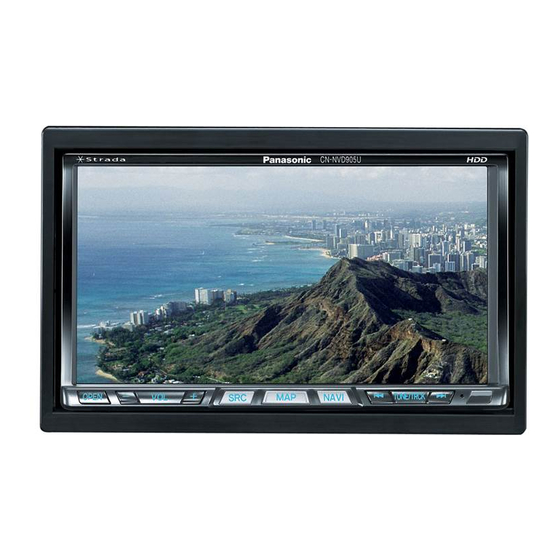
Panasonic Strada CN-NVD905U Installation Instructions Manual
Dual din in-dash hdd mobile navigation system with 7" widescreen color lcd monitor/dvd receiver
Hide thumbs
Also See for Strada CN-NVD905U:
- Operating instructions manual (118 pages) ,
- Instrucciones de operación (116 pages) ,
- Service manual (116 pages)
Dual DIN in-dash HDD Mobile Navigation System with 7 Widescreen Color
LCD Monitor/DVD Receiver
Système de navigation embarqué à disque dur de format 2-DIN
avec récepteur DVD/moniteur couleur ACL grand écran de 7 po
Sistema de navegación portátil de doble DIN para tablero de mandos, con
disco duro y monitor LCD panorámico de 7 en color y receptor con DVD
Read the "Safety information" presented in the Operating Instructions before
mounting or connecting this product.
Avant le montage ou le branchement du présent produit, veuillez lire les
« informations sur la sécurité » décrites dans le manuel d'instructions.
Lea la "Información de seguridad" que aparece en las Instrucciones de
funcionamiento antes de montar o conectar este producto.
CN-NVD905U
Installation Instructions
Instructions d'installation
Instrucciones de instalación

Summary of Contents for Panasonic Strada CN-NVD905U
- Page 1 DVD/moniteur couleur ACL grand écran de 7 po Sistema de navegación portátil de doble DIN para tablero de mandos, con disco duro y monitor LCD panorámico de 7 en color y receptor con DVD CN-NVD905U Installation Instructions Instructions d’installation Instrucciones de instalación...
-
Page 2: Installation Hardware
Installation hardware For installation Trim plate Mounting collar Mounting spring Rear support strap YEFC041589B YEFG013081A YEFX0052513 YEFG04019 Qty: 1 Qty: 1 Qty: 4 Qty: 1 Mounting Tapping Hex. nut Round head ... -
Page 3: Table Of Contents
Contents English Français Español Installation hardware ...........2 Contents ..............3 Installation guide ...........4 Mounting and removing the unit ......6 Mounting the GPS antenna ........8 Electrical connections ........10 External unit connections .........12 Note: The number in parentheses underneath each accessory part name is the part number for maintenance and service. -
Page 4: Installation Guide
Installation guide Transportation bracket removal Identify all leads Be sure to remove the transportation brackets before The fi rst step in installation is to identify all the car wires use (installation). Use round head screws (5 mm you will use when hooking up this unit. - Page 5 Final installation scraping sound in a speaker if you are holding a speaker lead. Lead connections If not, keep testing different lead combinations until you Connect all wires, making sure that each connection is have located all the speaker leads. When you label them, insulated and secure.
-
Page 6: Mounting And Removing The Unit
Mounting and removing the unit Mounting procedures (A) (When using Mounting collar ) IMPORTANT When this unit is installed in a dashboard, ensure that there is suffi cient air fl ow around the unit to prevent damage from overheating. Do not block any ventilation holes on the unit. Insert the Mounting collar ... - Page 7 Removing procedures Insert two fl athead screwdrivers between the unit and the mounting collar, then detach the four hooks. Establish the rear connection of the unit. Hook After fi xing Power connector , fi x the rear of the unit to the car body by either method (a) or (b).
-
Page 8: Mounting The Gps Antenna
Mounting the GPS antenna Preparation: Wipe all dirt (oil, dust, etc.) off the mounting surface, and dry any moisture. If the air temperature is low, use a hair drier, etc. to warm the mounting surface. To avoid interference, mount the GPS antenna at least 10 cm away from any other antenna. External mounting (recommended) Mount the GPS antenna on a fl... - Page 9 Mounting on the dashboard or rear tray Mount the antenna horizontally, in the center of the dashboard and close to the windscreen. Do not use the tip of a screwdriver or similar pointed implement to push the cord, as that could damage the cord or cause a malfunction.
-
Page 10: Electrical Connections
Electrical connections Warning This product is designed for operation with a negative grounded 12 V DC battery system. Never operate this product with other battery systems, especially a 24 V DC battery system. If it is used in the wrong type of car, it may cause a fi re or an accident. ... - Page 11 To the REMOTE IN connector of a TV tuner CN-NVD905U (Rear) Fuse (15 A) Refer fuse replacement to your nearest authorized Panasonic Servicenter. Do not attempt fuse replacement by yourself. Radio antenna connector (RADIO ANT IN) Power connector Rear view camera...
-
Page 12: External Unit Connections
External unit connections Also refer to the operating instructions for the connected devices. Connecting to the System-up connector The devices below can be connected. Use an Expansion module (CY-EM100U, option) if you need to connect two or more devices. iPod ®... - Page 13 CN-NVD905U (Rear) TV tuner (CY-TUN153U) RCA cord (supplied with CY-TUN153U) REMOTE OUT (Black) REMOTE-OUT Rear view camera connector R (Red) AV-IN L (White) Video input terminal Rear view camera – (AV-IN) RCA conversion cable Video (Yellow) TV Tuner (CY-TUN153U, option)
- Page 14 If multiple devices of the same type are connected at the same time, this unit will only recognize one of them. (For example, if three iPods are connected, only one will be recognized.) System-up connector CN-NVD905U (Rear) Head unit/Expansion module connecting cable...
- Page 16 Panasonic Consumer Panasonic Puerto Rico, Inc. Panasonic Canada Inc. Electronics Company, Ave. 65 de Infanteria, Km. 9.5 5770 Ambler Drive, San Gabriel Industrial Park, Mississauga, Ontario Division of Panasonic Carolina, Puerto Rico 00985 L4W 2T3 Corporation of North America http://www.panasonic.com http://www.panasonic.ca...


