Honeywell Thor VM2 User Manual
Vehicle mount computer microsoft windows embedded standard operating systems
Hide thumbs
Also See for Thor VM2:
- User manual (398 pages) ,
- Reference manual (196 pages) ,
- Quick start manual (12 pages)
Table of Contents
Quick Links
See also:
Reference Manual, User Manual
Table of Contents

Related Manuals for Honeywell Thor VM2


Summary of Contents for Honeywell Thor VM2
- Page 1 Thor™ VM2 Vehicle-Mount Computer Microsoft® Windows® Embedded Standard Operating System User's Guide...
-
Page 2: Limited Warranty
Disclaimer Honeywell International Inc. (“HII”) reserves the right to make changes in specifications and other information contained in this document without prior notice, and the reader should in all cases consult HII to determine whether any such changes have been made. The information in this publication does not represent a commitment on the part of HII. -
Page 3: Table Of Contents
Blue Key Orange Key 95-Key External Keyboard Keyboard Backlight USB Keyboard / Mouse Chapter 2 - Set Up A New Thor VM2 Hardware Setup Software Setup Quick Mount Smart Dock Preparing the Dock Place the Thor VM2 in the Dock... - Page 4 Setup Terminal Emulation Parameters 2-17 Cleaning the Touch Screen 2-18 Startup Help 2-19 Chapter 3 - Connecting Cables to the Thor VM2 Connect External Keyboard Connect Cable - USB Host Connect Cable - Serial Connect a Tethered Scanner Connecting an AC/DC Power Supply...
- Page 5 Screen Blanking with Switch 3-18 Fuse 3-19 Chapter 4 - Product Agency Compliance - Thor VM2 Lithium Battery Safety Statement Vehicle Power Supply Connection Safety Statement Chapter 5 - Technical Assistance...
-
Page 7: Chapter 1 - Introduction
The Thor VM2 contains a UPS battery which, when fully charged, can power the Thor VM2 for a minimum of 30 minutes. This can be when the Thor VM2 is not attached to a Quick Mount Smart Dock or when the Thor VM2 is attached to a dock but the vehicle power is interrupted, such as when the vehicle battery is being changed. -
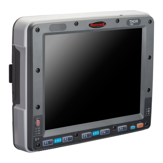
Page 8: Components
Components Front View 1. Power Button 2. Speakers 3. Microphone... -
Page 9: Back View Quick Mount Smart Dock
Back View Quick Mount Smart Dock 1. Antenna Connectors (on Thor VM2) 2. SIM card Access Panel (on Thor VM2) 3. COM1 Connector (on Dock) 4. COM2 Connector (on Dock) 5. USB Connector (on Dock) 6. CAN/Audio Connector (on Dock) 7. -
Page 10: Keyboard Options
Keyboard Options The Thor VM2 has an integrated keypad with five programmable keys and an available external keyboard. Integrated Keypad The integrated keypad contains five progammable keys, a blue modifier key and an orange modifier key. Press Orange plus P1-P5 to access P6-P10. The default programmable key functions are described below. Default functions may be overridden by custom settings. -
Page 11: Orange Key
Orange Key When the Orange LED is illuminated, the programmable keys provide the secondary function. Orange + P1 = P6 Orange + P2 = P7, etc. When the Orange modifier key is active, the LED located next to the key is illuminated. The modifier key remains active until: The Orange modifier key is pressed again, or A non-modifier key is pressed (i.e.: P1-P5), or The Blue modifier key is pressed. -
Page 12: 95-Key External Keyboard
95-Key External Keyboard The Thor VM2 uses an optional rugged QWERTY 95 key keyboard, designed for ease of use with the Windows CE operating system. The keyboard connects directly to the D9 USB connector on the Thor VM2 Quick Mount Smart Dock. -
Page 13: Chapter 2 - Set Up A New Thor Vm2
Chapter 2 - Set Up A New Thor VM2 This page lists a quick outline of the steps you might take when setting up a new Thor VM2. More instruction for each step is listed later in this guide. Please refer to the Thor VM2 Reference Guide for additional information and instruction. -
Page 14: Quick Mount Smart Dock
The Thor VM2 assembly consists of two parts, the Thor VM2 computer and the Quick Mount Smart Dock. The Thor VM2 contains an internal UPS battery that, once fully charged, powers the Thor VM2 for a minimum of 30 minutes when the unit is not mounted in the dock. -
Page 15: Preparing The Dock
Preparing the Dock 1. Attach RAM mount to vehicle (see Thor VM2 Vehicle Mounting Reference Guide). Attach accessories to dock. 3. Attach power cable, 10-60VDC or 72-144VDC. 4. If the tethered I/O port cover is in place, lift the cover to expose the I/O port on the dock. The tether allows the cover to... -
Page 16: Place The Thor Vm2 In The Dock
1. Locate the notch on the upper rear of the Thor VM2 (item A above). 2. Slide this notch over the top lip (C) of the Dock. Slide the Thor VM2 from side to side on the Dock to make sure it fully engages on the lip of the Dock. -
Page 17: Backlights And Indicators
Power Management The display backlight is controlled by power management. When the user activity timer expires, the display backlight is turned off. Different timeouts can be set for when the Thor VM2 is operating in the following power management schemes: AC/DC... -
Page 18: Led Functions
LED Functions System LEDs Connection LEDs Blue LED Orange LED Programmable LED... -
Page 19: System Leds
System LEDs 1. SYS (System Status) LED 2. UPS (Uninterruptible Power Supply) LED 3. SSD (Solid State Drive) LED SYS (System Status) LED LED Behavior System State Solid Green On but Display Off Green blinking very slowly External power present Standby (1/2 sec. -
Page 20: Ups Status Led
UPS Status LED The color of the UPS LED identifies the charge level and the behavior of the LED identifies the charging state. Charge Level LED Color Status Green Fully charged (>90%) Less than fully charged, but more than 2 minutes runtime remaining, Out of charging temperature range, Amber... -
Page 21: Connection Leds
Connection LEDs 1. WWAN LED 2. WiFi LED 3. Bluetooth LED WWAN LED LED Behavior Status Solid Green Indicates a WWAN connection to a network. Indicates no WWAN connection. WiFi LED LED Behavior Status Solid Green Indicates a connection with an IP address to an Access Point Indicates no connection to an Access Point. -
Page 22: Keyboard Leds
Keyboard LEDs The keyboard LEDs are located near the specified key. Blue LED LED Behavior Status Indicates the Blue modifier key is active. Blue modifier mode is invoked for the next keypress. Pressing the Blue key a second time exits this modifier mode and turns off the LED. -
Page 23: Power Up
After external power has been connected and the Thor VM2 has been mounted in the Dock, press the side of the power switch with the raised bump to pass power from the Dock to the Thor VM2. Generally, once the Dock is powered On, there is no need to power if Off. -
Page 24: Tapping The Touch Screen With A Stylus
Tapping the Touch Screen with a Stylus Note: Always use the point of the stylus for tapping or making strokes on the touch screen. Never use an actual pen, pencil, or sharp/abrasive object to write on the touch screen. Hold the stylus as if it were a pen or pencil. Touch an element on the screen with the tip of the stylus then remove the stylus from the screen. -
Page 25: Thor Vm2 Configuration Options
Thor VM2 Configuration Options Many configuration options are available via the Microsoft Windows Control panel. Refer to the Thor VM2 Reference Guide or For Help and Support on the Start menu for configuration details. Date and Time Use the Windows interface to set date, time and time zone. -
Page 26: Restart/Shutdown
Restart/Shutdown Use the Windows interface to restart or shut down the Thor VM2. Tap Start > Shut Down > Restart Tap Start > Shut Down > Shut down Calibrate Touch Screen To calibrate the touch screen, access the touch screen software. Select: Tap Start >... -
Page 27: Touch Screen
Touch Screen Apply the Touch Screen Protective Film The Thor VM2 touch screen protective film is shipped in packs of 10. The protective film is flexible and treated with an anti- glare coating on the outer surface. The protective film is slightly larger than the Thor VM2 touch screen, however the notches on the edge of the protective film (indicated by arrows 1 - 4 above) correspond to the display size of the Thor VM2. -
Page 28: Removal
2. Lift up on the edge of the protective film so it does not slide between the touch screen and display housing when the protective film is slid back to the center. 3. Repeat until all edges are free and remove the protective film. Contact Technical Assistance about protective film packs designed specifically for your Thor VM2 touch screen. 2-16... -
Page 29: Setup Terminal Emulation Parameters
Setup Terminal Emulation Parameters Before you make a host connection, you will, at a minimum, need to know: the alias name or IP address (Host Address) and the port number (Telnet Port) of the host system to properly set up your host session. 1. -
Page 30: Cleaning The Touch Screen
Cleaning the Touch Screen Note: These instructions are for components made of glass. If there is a removable protective film sheet on the display, remove the film sheet before cleaning the screen. Keep fingers and rough or sharp objects away from the bar code reader scanning aperture and the mobile device touch screen. If the glass becomes soiled or smudged, clean only with a standard household cleaner such as Windex®... -
Page 31: Startup Help
There may be slight delays while the wireless client connects to the network, authorization Thor VM2 seems to lockup as for voice-enabled applications complete, and Bluetooth relationships establish or re-estab- soon as it is rebooted. lish. When an application begins, the Thor VM2 is ready for use. 2-19... - Page 32 2-20...
-
Page 33: Chapter 3 - Connecting Cables To The Thor Vm2
A USB Client connection is not used on Thor VM2 with a Windows Embedded Standard operating system. Connect External Keyboard The Thor VM2 supports an optional external 95-key USB keyboard. The external keyboard has a D9 connector to connect to the USB port on the Thor VM2 Quick Mount Smart Dock. -
Page 34: Connect Cable - Usb Host
Connect Cable - USB Host Note: A USB Client connection is not used on Thor VM2 with a Windows Embedded Standard operating system. 1. D9 Connector 2. USB Client Connector (not used) 3. USB Host Connector (for connecting to a USB device) 1. -
Page 35: Connect Cable - Serial
1. The scanner cable is attached to either the COM1 or COM2 port on the Quick Mount Smart Dock. 2. Connect the serial cable for the scanner as directed above. 3. When the Thor VM2 is powered on, it provides power to the serial scanner. -
Page 36: Connecting An Ac/Dc Power Supply
15 Amp overcurrent protection (10 Amp for 230V circuits). 1. Turn the Thor VM2 off. 2. Connect the detachable cordset provided by Honeywell (US only, all others must provide their own cable) to the external power supply (IEC 320 connector). -
Page 37: Connecting The Headset Cable
2. Tighten the thumbscrews in a clockwise direction. Do not over tighten. 3. Slide the cable ends together until they click shut. Do not twist or bend the connectors. The Thor VM2 internal microphone and speakers are automatically disabled when the headset is connected. -
Page 38: Adjust Headset / Microphone And Secure Cable
The headset consists of an earpiece, a microphone, a clothing clip and a cable. The headset attaches to the audio cable end of the voice cable which attaches to the Thor VM2. Align the audio connector and the headset quick connect cable end. Firmly push the cable ends together until they click and lock in place. -
Page 39: Connecting Vehicle Power
Correct electrical polarity is required for safe and proper installation. See the figures below for additional wire color- coding specifics. The Thor VM2 DC input wires (Red DC+ and Black DC-) and the Blue ignition input wire are galvanically isolated. The Green ground input is used for electrostatic discharge (ESD) protection. -
Page 40: Connect Vehicle 10-60Vdc
Connect Vehicle 10-60VDC 1. The Thor VM2 must not be mounted in the Quick Mount Smart Dock. The power switch on the Dock must be turned Off. The power cable must be UNPLUGGED from the Dock. 2. While observing the fuse requirements specified above, connect the power cable as close as possible to the actual battery terminals of the vehicle (if using unswitched power). -
Page 41: Ignition Control
Thor VM2 ignition signal wire can be connected (less than 1mA over input voltage range) to the switched circuit to allow the Thor VM2 to power on when the vehicle is switched on. When the vehicle is switched off, more aggressive power management settings are enabled to preserve the vehicle battery charge. -
Page 42: Auto-On Control
On position. The Ignition wire is not used and should be left disconnected. 1. Existing Circuitry on Vehicle 2. Forklift Battery 9. Thor VM2 Computer in Quick Mount Smart Dock 3. Main Switch 10. COM1 or COM2 Connector on Dock 4. -
Page 43: Manual Control
1. Existing Circuitry on Vehicle 8. Blue Wire (not connected) 2. Forklift Battery 9. Thor VM2 Computer in Quick Mount Smart Dock 3. Main Switch 10. COM1 or COM2 Connector on Dock 4. 10A Slow blow Fuse close to power source 11. -
Page 44: Vx6 / Vx7 Adapter Cable
VX6 / VX7 Adapter Cable An adapter cable is available to attach the Thor VM2 to a vehicle previously equipped with a VX6/VX7 DC power cable. The adapter cable has a 5-pin connector to match with the VX6/VX7 power supply cable on one end and a 6-pin connector to match to the Thor VM2 on the other. -
Page 45: Vehicle 72-144Vdc Power Connection
Vehicle 72-144VDC Power Connection This option requires DC/DC external power supply Part no. VX89303PWRSPLY. Caution: For installation by trained service personnel only. Caution: For proper and safe installation, the input power cable must be connected to a fused circuit on the vehicle. This fused circuit requires a 10 Amp maximum time delay (slow blow) high interrupting rating fuse. -
Page 46: Connect Vehicle 72-144Vdc
(ESD) protection. Connect Vehicle 72-144VDC 1. The Thor VM2 must not be mounted in the Quick Mount Smart Dock. The power switch on the Dock must be turned Off. The power cable must be UNPLUGGED from the Dock. -
Page 47: Wiring Diagram
5. Connect the DC power cable to the input connector on the back of the Dock. 6. Flip the power switch on the back of the Dock to On. 7. The Thor VM2 can be installed in the Dock. 8. If using the optional screen blanking feature, install the screen blanking box or switch. -
Page 48: Thor Vm2 Screen Blanking
Thor VM2 Screen Blanking Note: Before this process begins, the steps outlined in Power Cable Connection need to be performed for either the 60VDC Connection or the 72-144VDC Connection. Caution: For installation by trained service personnel only. Caution: For proper and safe installation, the input power lead to the Screen Blanking Box requires a 3 Amp maximum time delay (slow blow) high interrupting rating fuse. -
Page 49: Screen Blanking Box
Screen Blanking Box Screen Blanking Box Connection Terminal Input from vehicle motion sensing circuitry. 12-xxV Please refer to label on Screen Blanking Box for allowable voltage input range. DC - These two terminals are for a user provided serial cable. The cable must be constructed so that Pin 7 (RTS) connects to switched side of the connection and Pin 8 (CTS) connects to the other terminal. -
Page 50: Screen Blanking With Switch
Screen Blanking with Switch In applications where it is impractical to use the screen blanking box due to vehicle voltage or lack of a motion sensing signal, screen blanking can be controlled via a user supplied switch or relay that provides an electrical conductive connection on vehicle motion. -
Page 51: Fuse
Fuse The Thor VM2 uses an 8A time delay (slow blow), fuse that is externally accessible and user replaceable. The fuse is located on the back of the Quick Mount Smart Dock. The fuse is accessed by unscrewing the cap as indicated below. - Page 52 3-20...
-
Page 53: Chapter 4 - Product Agency Compliance - Thor Vm2
Connect the equipment into an outlet on a circuit different from that to which the receiver is connected. Consult the dealer or an experienced radio/TV technician for help. Notice Changes or modifications made to this equipment not expressly approved by Honeywell may void the FCC authorization to operate this equipment. EMC Directive Requirements This is a Class B product. - Page 54 Li-Ion Battery When disposing of the Thor VM2 UPS battery, the following precautions should be observed: The battery should be disposed of properly. The battery should not be disassembled or crushed. The battery should not be heated above 212°F (100°C) or incinerated.
- Page 55 Waste Electrical and Electronic Equipment (WEEE) Important: This symbol is placed on the product to remind users to dispose of Waste Electrical and Electronic Equipment (WEEE) appropriately, per Directive 2002-96-EC. In most areas, this product can be recycled, reclaimed and re- used when properly discarded.
- Page 56 R&TTE Directive Requirements This device bearing the CE marking is in compliance with the essential requirements and other relevant provisions of Directive 1999/5/EC. This device complies with the following harmonized European Standards: Health: EN63211:2008 Safety: EN60950-1:2006 + A1:2010 + A11:2009 + A12:2011 EMC: EN301 489-1 V1.9.2:2011, EN301 489-17 V2.1.1:2009 Radio: EN300 328 V1.7.1:2006 The following CE marking is valid for EU harmonized telecommunications products.
-
Page 57: Lithium Battery Safety Statement
Lithium Battery Safety Statement Caution: Lithium battery inside. Danger of explosion if battery is incorrectly replaced. Replace only with same or equivalent type recommended by battery manufacturer. (US) Attention: Contient une pile de lithium. Risque d’explosion dans le cas où la pile ne serait pas correctement remplacée. Remplacer uniquement avec une pile semblable ou equivalente au type de pile recommandé... - Page 58 Lithium Battery Safety Statement, continued Legend: Chinese – CN; Danish – DK; Dutch – NL; English – US; Finnish – FI; French- - FR; German – DE; Greek – GR; Italian – IT; Japanese – JP; Korean – KR; Norwegian – NO; Portuguese – PT; Spanish – ES; Swedish – SE; Turkish – TR.
-
Page 59: Vehicle Power Supply Connection Safety Statement
Vehicle Power Supply Connection Safety Statement Vehicle Power Supply Connection: If the supply connection is made directly to the battery, a 10A slow-blow fuse should be installed in the positive lead within 5 inches (12.7 cm.) of the battery positive (+) terminal. (US) Raccordement de l’alimentation du véhicule Si l’alimentation est raccordée directement à... -
Page 61: Chapter 5 - Technical Assistance
Limited Warranty Honeywell International Inc. ("HII") warrants its products to be free from defects in materials and workmanship and to conform to HII’s published specifications applicable to the products purchased at the time of shipment. This warranty does not cover any HII product which is (i) improperly installed or used;... - Page 62 The duration of the limited warranty for the Thor VM2 is 1 year. The duration of the limited warranty for the Thor VM2 Quick Mount Smart Dock is 1 year. The duration of the limited warranty for the Thor VM2 Vehicle Mount Assembly is 1 year.
- Page 64 Honeywell Scanning & Mobility 9680 Old Bailes Road Fort Mill, SC 29707 www.honeywellaidc.com E-EQ-VM2WESOGWW Rev A 1/13...