Siemens SINAMICS S120 Manual
Chassis power units
Hide thumbs
Also See for SINAMICS S120:
- Function manual (1094 pages) ,
- Diagnostic manual (947 pages) ,
- Manual (848 pages)
Table of Contents
Quick Links
Table of Contents

Related Manuals for Siemens SINAMICS S120


Summary of Contents for Siemens SINAMICS S120
- Page 1 SINAMICS S120 Chassis Power Units Manual 01/2013 SINAMICS...
- Page 3 ___________________ Chassis power units Preface ___________________ System overview ___________________ Line-side power components SINAMICS ___________________ Line Modules S120 ___________________ Chassis power units Motor Modules ___________________ DC link components Manual Motor-side power ___________________ components ___________________ Cabinet design and EMC ___________________ Maintenance and Servicing ___________________ Appendix (GH3), 01/2013...
- Page 4 Note the following: WARNING Siemens products may only be used for the applications described in the catalog and in the relevant technical documentation. If products and components from other manufacturers are used, these must be recommended or approved by Siemens. Proper transport, storage, installation, assembly, commissioning, operation and maintenance are required to ensure that the products operate safely and without any problems.
-
Page 5: Preface
Siemens' content, and adapt it for your own machine documentation: http://www.siemens.com/mdm Training Using the following link, you can find information on SITRAIN - training from Siemens for products, systems and drive technology solutions: http://www.siemens.com/sitrain FAQs You can find Frequently Asked Questions in the Service&Support pages under Product Support: http://support.automation.siemens.com... - Page 6 SIZER engineering tool • Configuration manuals, motors • Decision making/ordering SINAMICS S Catalogs Configuring/installation SINAMICS S120 Manual for Control Units and Additional System • Components SINAMICS S120 Manual for Booksize Power Units • SINAMICS S120 Manual for Chassis Power Units •...
-
Page 7: Technical Support
EC declarations of conformity The EC Declaration of Conformity for the EMC Directive and for the Low-Voltage Directive can be found/obtained from the relevant regional office of the I DT MC and I DT LD Business Units of Siemens AG. Note Low-voltage directive When operated in dry operating areas, SINAMICS equipment with AC motors conforms to Low-Voltage Directive 2006/95/EC. - Page 8 The Safety Integrated functions of SINAMICS components are generally certified by independent institutes. An up-to-date list of certified components is available on request from your local Siemens office. If you have any questions relating to certifications that have not been completed, please ask your Siemens contact.
- Page 9 Preface ESD information CAUTION Electrostatic sensitive devices Electrostatic sensitive devices (ESD) are single components, integrated circuits or devices that can be damaged by electrostatic fields or electrostatic discharges. Regulations for handling ESD components: • During the handling of electronic components, pay attention to the grounding of the person, workplace and packaging! •...
- Page 10 Preface Safety information DANGER Qualified personnel SINAMICS S equipment must only be commissioned by suitably qualified personnel. The personnel must take into account the information provided in the technical customer documentation for the product, and be familiar with and follow the specified danger and warning notices.
- Page 11 Preface Note Installation of a UL-approved system For a UL-approved system use 60/75° C copper conductors only. NOTICE Malfunctions caused by mobile telephones Operating the equipment in the immediate vicinity (< 1.8 m) of mobile telephones with a transmitting power of > 1 W may cause the devices to malfunction. Chassis power units Manual, (GH3), 01/2013, 6SL3097-4AE00-0BP3...
- Page 12 Preface Residual risks of power drive systems The control and drive components of a power drive system (PDS) are approved for industrial and commercial use in industrial line supplies. Their use in public electrical networks requires a different configuration and/or additional measures. These components may only be operated in closed housings or in higher-level control cabinets with protective covers that are closed, and when all of the protective devices are used.
- Page 13 Preface 4. Electrical, magnetic and electromagnetic fields generated in operation that can pose a risk to people with a pacemaker, implants or metal replacement joints, etc. if they are too close. 5. Release of environmental pollutants or emissions as a result of improper operation of the system and/or failure to dispose of components safely and correctly.
- Page 14 Preface Electromagnetic fields WARNING Electromagnetic fields "electro smog" Electromagnetic fields are generated by the operation of electrical power engineering installations such as transformers, converters or motors. Electromagnetic fields can interfere with electronic devices, which could cause them to malfunction. For example, the operation of heart pacemakers can be impaired, potentially leading to damage to a person's health or even death.
-
Page 15: Table Of Contents
Basic structure of a drive system with SINAMICS S120 .............33 1.6.1 Structure of a drive system with SINAMICS S120 and regulated infeed........33 1.6.2 Structure of a drive system with SINAMICS S120 and unregulated infeed / regenerative feedback............................34 1.6.3 Structure of a drive system with SINAMICS S120 and unregulated infeed.........35 Line-side power components ........................ - Page 16 Table of contents 2.6.3.3 Line/load connection ........................70 2.6.3.4 DRIVE-CLiQ interface X500......................70 2.6.3.5 X530 neutral point grounding ...................... 71 2.6.3.6 X609 terminal strip ........................72 2.6.3.7 Meaning of the LED on the Voltage Sensing Module (VSM) in the Active Interface Module ..73 2.6.4 Dimension drawing........................
- Page 17 Table of contents 3.4.3.6 X42 terminal strip ........................159 3.4.3.7 DRIVE-CLiQ interfaces X400, X401, X402................160 3.4.3.8 Meaning of the LEDs on the Control Interface Module in the Active Line Module ....161 3.4.4 Dimension drawing ........................162 3.4.5 Electrical connection ........................166 3.4.6 Technical specifications ......................168 Motor Modules............................
- Page 18 Table of contents 5.1.4.4 Installing the Braking Module in a Smart Line Module / Active Line Module / Motor Module, frame size JX....................... 234 5.1.4.5 Installing the Braking Module in a Basic Line Module, frame size FB ........235 5.1.4.6 Installing the Braking Module in a Basic Line Module, frame size GB, GD ......
- Page 19 Table of contents Maintenance and Servicing........................319 Chapter content .........................319 Maintenance..........................319 Maintenance..........................320 8.3.1 Installation device ........................322 8.3.2 Using crane lifting lugs to transport power blocks ..............323 Replacing components ......................326 8.4.1 Safety information ........................326 8.4.2 Replacing the power block, Active Line Module, and Motor Module, frame size FX....327 8.4.3 Replacing the power block, Smart Line Module, Active Line Module, and Motor Module, frame size GX ..........................330...
- Page 20 Table of contents Chassis power units Manual, (GH3), 01/2013, 6SL3097-4AE00-0BP3...
-
Page 21: System Overview
The SINAMICS range of drives Field of application SINAMICS is the family of drives from Siemens designed for machine and plant engineering applications. SINAMICS offers solutions for all drive tasks: ● Simple pump and fan applications in the process industry ●... - Page 22 The different SINAMICS versions can be easily combined with each other. SINAMICS is part of the Siemens "Totally Integrated Automation" concept. Integrated SINAMICS systems covering engineering, data management and communication at the automation level, result in extremely cost-effective solutions based on SIMOTION, SINUMERIK and SIMATIC control systems.
- Page 23 System overview 1.1 The SINAMICS range of drives Figure 1-2 SINAMICS as part of the Siemens modular automation system Quality management according to DIN EN ISO 9001 SINAMICS is able to meet the highest requirements in terms of quality. Comprehensive quality assurance measures in all development and production processes ensure a consistently high level of quality.
-
Page 24: Sinamics S120 Drive System
SIZER, a high-performance engineering tool, makes it easier to choose and determine the optimum drive configuration. SINAMICS S120 is enhanced by a wide range of motors. Whether synchronous or induction, all motor types are supported by SINAMICS S120. - Page 25 SINAMICS S120 takes a different approach. A central Control Unit controls the drive for all connected axes and also establishes the technological links between the drives and/or axes.
- Page 26 1.2 SINAMICS S120 drive system DRIVE-CLiQ – the digital interface between all components All SINAMICS S120 components, including the motors and encoders, are interconnected by a shared serial interface called DRIVE-CLiQ. The standardized cables and connectors reduce the variety of different parts and cut storage costs.
- Page 27 System overview 1.2 SINAMICS S120 drive system SINAMICS S120 components were developed for installation in cabinets. They have the following features and characteristics: ● Easy to handle, simple installation and wiring ● Practical connection system, cable routing according to EMC requirements ●...
-
Page 28: Technical Specifications
System overview 1.3 Technical specifications Technical specifications Technical data Unless specified otherwise, the following technical data is valid for all the following components of the SINAMICS S120 drive system. Table 1- 1 General technical data Electrical data Line supply voltage 3 AC 380 V -10% (-15% <... - Page 29 System overview 1.3 Technical specifications Ambient conditions Degree of protection IP00 or IP20 according to EN 60529 Protection class Class I (with protective conductor system) and class III (PELV) according to EN 61800-5-1 Shock protection EN 50274 and BGV A 3 when used as intended Permissible ambient and coolant 0 ...
- Page 30 System overview 1.3 Technical specifications Installation altitude > 2000 m above sea level without derating • > 2000 ... 4000 m above sea level, see derating characteristics • Certificates Conformity CE (Low Voltage and EMC Directives), Machinery Directive Standards EN 61800-5-1, EN 60204-1, EN 61800-3, EN 60146-1-1 Approvals (only up to 3 AC 600 V) cULus (File Nos.: E192450, E214113 and E253831) In transport packaging...
-
Page 31: Derating Factors As A Function Of Installation Altitude And Ambient Temperature
System overview 1.4 Derating factors as a function of installation altitude and ambient temperature Derating factors as a function of installation altitude and ambient temperature Chassis units and the associated system components are rated for an ambient temperature of 40° C and installation altitudes up to 2000 m above sea level. At ambient temperatures >... -
Page 32: Standards
System overview 1.5 Standards Standards Note Information on the listed standards The standards listed in the table below are non-binding and do not in any way claim to be complete. The standards listed do not represent a guaranteed property of the product. Only the statements made in the Declaration of Conformity shall be deemed binding. - Page 33 System overview 1.5 Standards Standards* Title IEC 60287-1 to -3 Cables - Calculation of the current carrying capacity Part 1: Current carrying capacity equations (100 % load factor) and calculating the losses Part 2: Thermal resistance - Part 3: Main sections for operating conditions HD 60364-x-x Erection of power installations with nominal voltages up to 1000 V;...
- Page 34 System overview 1.5 Standards Standards* Title EN 61800-5-x Adjustable-speed electrical power drive systems; IEC 61800-5-x Part 5: Safety requirements; DIN EN 61800-5-x Main section 1: Electrical, thermal and energy requirements VDE 0160-105-x Main section 2: Functional safety requirements EN 62061 Safety of machinery;...
-
Page 35: Basic Structure Of A Drive System With Sinamics S120
Basic structure of a drive system with SINAMICS S120 1.6.1 Structure of a drive system with SINAMICS S120 and regulated infeed Figure 1-4 Basic structure of a drive system with SINAMICS S120 and regulated infeed Chassis power units Manual, (GH3), 01/2013, 6SL3097-4AE00-0BP3... -
Page 36: Structure Of A Drive System With Sinamics S120 And Unregulated Infeed / Regenerative Feedback
1.6 Basic structure of a drive system with SINAMICS S120 1.6.2 Structure of a drive system with SINAMICS S120 and unregulated infeed / regenerative feedback Figure 1-5 Basic structure of a drive system with SINAMICS S120 and unregulated infeed / regenerative feedback Chassis power units Manual, (GH3), 01/2013, 6SL3097-4AE00-0BP3... -
Page 37: Structure Of A Drive System With Sinamics S120 And Unregulated Infeed
1.6 Basic structure of a drive system with SINAMICS S120 1.6.3 Structure of a drive system with SINAMICS S120 and unregulated infeed Figure 1-6 Basic structure of a drive system with SINAMICS S120 and unregulated infeed Chassis power units Manual, (GH3), 01/2013, 6SL3097-4AE00-0BP3... - Page 38 System overview 1.6 Basic structure of a drive system with SINAMICS S120 Chassis power units Manual, (GH3), 01/2013, 6SL3097-4AE00-0BP3...
-
Page 39: Line-Side Power Components
Line-side power components General Line-side power components are used to protect the connected components against transient or continuous overvoltages and ensure that prescribed limit values are adhered to. Line filters for Basic Line Modules 2.2.1 Description The line filters limit the conducted interference emitted by the Power Modules to permissible values. - Page 40 (Page 102) "Electrical connection". NOTICE Use only approved line filters Using line filters not approved by SIEMENS for SINAMICS can lead to line-side harmonics that can interfere with or damage other loads powered from the network. Chassis power units...
-
Page 41: Dimension Drawing
Line-side power components 2.2 Line filters for Basic Line Modules 2.2.3 Dimension drawing Figure 2-1 Dimension drawing of line filters for Basic Line Modules Chassis power units Manual, (GH3), 01/2013, 6SL3097-4AE00-0BP3... - Page 42 Line-side power components 2.2 Line filters for Basic Line Modules Table 2- 1 Dimensions of line filters for Basic Line Modules (all data in mm) 6SL3000- 0BE34-4AA0 0BE36-0AA0 0BE41-2AA0 0BE41-6AA0 0BG34-4AA0 0BG36-0AA0 0BG41-2AA0 0BG41-6AA0 – – – 78.2 127.5 127.5 Lengths n1 and n2 correspond to the distance between holes Chassis power units Manual, (GH3), 01/2013, 6SL3097-4AE00-0BP3...
-
Page 43: Technical Data
Line-side power components 2.2 Line filters for Basic Line Modules 2.2.4 Technical data Table 2- 2 Technical data of line filters for Basic Line Modules, 3 AC 380 ... 480 V, Part 1 Order number 6SL3000- 0BE34-4AA0 0BE36-0AA0 0BE41-2AA0 0BE41-2AA0 Suitable for 6SL3330- 1TE34-2AAx... - Page 44 Line-side power components 2.2 Line filters for Basic Line Modules Table 2- 4 Technical data of line filters for Basic Line Modules, 3 AC 500 ... 690 V, Part 1 Order number 6SL3000- 0BG34-4AA0 0BG34-4AA0 0BG36-0AA0 0BG41-2AA0 Suitable for 6SL3330- 1TG33-3AAx 1TG34-3AAx 1TG36-8AAx...
-
Page 45: Line Filters For Smart Line Modules And Active Line Modules
Line-side power components 2.3 Line filters for Smart Line Modules and Active Line Modules Line filters for Smart Line Modules and Active Line Modules 2.3.1 Description The line filters limit the conducted interference emitted by the Power Modules to permissible values. - Page 46 Interface Module. NOTICE Use only approved line filters Using line filters not approved by SIEMENS for SINAMICS can lead to line-side harmonics that can interfere with or damage other loads powered from the network. Chassis power units Manual, (GH3), 01/2013, 6SL3097-4AE00-0BP3...
-
Page 47: Dimension Drawing
Line-side power components 2.3 Line filters for Smart Line Modules and Active Line Modules 2.3.3 Dimension drawing Figure 2-2 Dimension drawing for Line filters for Smart Line Modules and Active Line Modules Chassis power units Manual, (GH3), 01/2013, 6SL3097-4AE00-0BP3... - Page 48 Line-side power components 2.3 Line filters for Smart Line Modules and Active Line Modules Table 2- 6 Dimensions of the line filters for Smart Line Modules and Active Line Modules, 380 V ... 480 V 3 AC (all specifications in mm) 6SL3000- 6SL3000- 6SL3760-...
- Page 49 Line-side power components 2.3 Line filters for Smart Line Modules and Active Line Modules Table 2- 7 Dimensions of the line filters for Smart Line Modules and Active Line Modules, 500 V ... 690 V 3 AC (all specifications in mm) 6SL3760- 6SL3760- 6SL3760-...
-
Page 50: Technical Data
Line-side power components 2.3 Line filters for Smart Line Modules and Active Line Modules 2.3.4 Technical data Table 2- 8 Technical data of the line filters for the Smart Line Modules and Active Line Modules, 3 AC 380 V ... 480 V Order number 6SL3000- 6SL3000-... -
Page 51: Line Reactors For Basic Line Modules
The connecting cables to the Line Module must be kept as short as possible (max. 5 m). NOTICE Use only approved line reactors When using line reactors that have not been approved by SIEMENS for SINAMICS, the following can occur: • The Basic Line Modules may become damaged/faulty. -
Page 52: Dimension Drawing
Line-side power components 2.4 Line reactors for Basic Line Modules 2.4.3 Dimension drawing Figure 2-3 Dimension drawing of line reactors for Basic Line Modules Chassis power units Manual, (GH3), 01/2013, 6SL3097-4AE00-0BP3... - Page 53 Line-side power components 2.4 Line reactors for Basic Line Modules Table 2- 10 Dimensions of line reactors for Basic Line Modules, 3 AC 380 V ... 480 V (all values in mm) 6SL3000- 0CE35-1AA0 0CE37-7AA0 0CE41-0AA0 0CE41-5AA0 0CE41-6AA0 152.5 152.5 212.5 212.5 211.5...
-
Page 54: Technical Data
Line-side power components 2.4 Line reactors for Basic Line Modules 2.4.4 Technical data Table 2- 12 Technical data of line reactors for Basic Line Modules, 3 AC 380 ... 480 V, Part 1 Order number 6SL3000- 0CE35-1AA0 0CE35-1AA0 0CE37-7AA0 0CE41-0AA0 Suitable for 6SL3330- 1TE34-2AAx... - Page 55 Line-side power components 2.4 Line reactors for Basic Line Modules Table 2- 14 Technical data of line reactors for Basic Line Modules, 3 AC 500 ... 690 V, Part 1 Order number 6SL3000- 0CH32-7AA0 0CH34-8AA0 0CH36-0AA0 0CH41-2AA0 Suitable for 6SL3330- 1TG33-0AAx 1TG34-3AAx 1TG36-8AAx...
-
Page 56: Line Reactors For Smart Line Modules
The connecting cables to the Line Module must be kept as short as possible (max. 5 m). NOTICE Use only approved line reactors When using line reactors that have not been approved by SIEMENS for SINAMICS, the following can occur: • The Smart Line Modules may become damaged/faulty. -
Page 57: Dimension Drawing
Line-side power components 2.5 Line reactors for Smart Line Modules 2.5.3 Dimension drawing Line reactor 6SL3000-0EE36-2AA0 Figure 2-4 Dimension drawing of line reactor 6SL3000-0EE36-2AA0 Table 2- 16 Dimensions (all dimensions in mm) – – Lengths D and E correspond to the distance between holes Chassis power units Manual, (GH3), 01/2013, 6SL3097-4AE00-0BP3... - Page 58 Line-side power components 2.5 Line reactors for Smart Line Modules Line reactor 6SL3000-0EE38-8AA0 Figure 2-5 Dimension drawing of line reactor 6SL3000-0EE38-8AA0, all dimensions in mm Chassis power units Manual, (GH3), 01/2013, 6SL3097-4AE00-0BP3...
- Page 59 Line-side power components 2.5 Line reactors for Smart Line Modules Line reactor 6SL3000-0EE41-4AA0 Figure 2-6 Dimension drawing of line reactor 6SL3000-0EE41-4AA0 Table 2- 17 Dimensions (all dimensions in mm) 80.5 130.5 Lengths D and E correspond to the distance between holes Note Remove the crane lifting eyes The crane lifting eyes can be removed after installation.
- Page 60 Line-side power components 2.5 Line reactors for Smart Line Modules Line reactor 6SL3000-0EH34-7AA0 Figure 2-7 Dimension drawing of line reactor 6SL3000-0EH34-7AA0 Table 2- 18 Dimensions (all dimensions in mm) 16.5 – – Lengths D and E correspond to the distance between holes Chassis power units Manual, (GH3), 01/2013, 6SL3097-4AE00-0BP3...
- Page 61 Line-side power components 2.5 Line reactors for Smart Line Modules Line reactor 6SL3000-0EH37-6AA0 Figure 2-8 Dimension drawing of line reactor 6SL3000-0EE37-6AA0, all dimensions in mm Note Remove the crane lifting eyes The crane lifting eyes can be removed after installation. Chassis power units Manual, (GH3), 01/2013, 6SL3097-4AE00-0BP3...
- Page 62 Line-side power components 2.5 Line reactors for Smart Line Modules Line reactor 6SL3000-0EE41-4AA0 Figure 2-9 Dimension drawing of line reactor 6SL3000-0EH41-4AA0 Table 2- 19 Dimensions (all dimensions in mm) 88.5 79.5 236.5 139.5 149.5 108.5 Lengths D and E correspond to the distance between holes Note Remove the crane lifting eyes The crane lifting eyes can be removed after installation.
-
Page 63: Technical Data
Line-side power components 2.5 Line reactors for Smart Line Modules 2.5.4 Technical data Table 2- 20 Technical data, line reactors for Smart Line Modules, 3 AC 380 ... 480 V Order number 6SL3000- 0EE36-2AA0 0EE36-2AA0 0EE38-8AA0 0EE41-4AA0 0EE41-4AA0 Suitable for 6SL3330- 6TE35-5AAx 6TE37-3AAx... -
Page 64: Active Interface Modules
Line-side power components 2.6 Active Interface Modules Active Interface Modules 2.6.1 Description Active Interface Modules are used in conjunction with the Active Line Modules in chassis format. The Active Interface Modules contain a Clean Power Filter with basic RI suppression, the precharging circuit for the Active Line Module, the line voltage sensing circuit and monitoring sensors. -
Page 65: Safety Information
Line-side power components 2.6 Active Interface Modules 2.6.2 Safety information CAUTION Danger notice in the local language The DC-link discharge time hazard warning must be affixed to the component in the relevant local language. Note Maintain ventilation clearances The ventilation clearances above, below, and in front of the component, which are specified in the dimension drawings, must be observed. -
Page 66: Interface Description
Line-side power components 2.6 Active Interface Modules 2.6.3 Interface description 2.6.3.1 Overview Figure 2-10 Interface overview in the Active Interface Module, frame size FI Chassis power units Manual, (GH3), 01/2013, 6SL3097-4AE00-0BP3... - Page 67 Line-side power components 2.6 Active Interface Modules Figure 2-11 Interface overview in the Active Interface Module, frame size GI Chassis power units Manual, (GH3), 01/2013, 6SL3097-4AE00-0BP3...
- Page 68 Line-side power components 2.6 Active Interface Modules Figure 2-12 Interface overview in the Active Interface Module, frame size HI Chassis power units Manual, (GH3), 01/2013, 6SL3097-4AE00-0BP3...
- Page 69 Line-side power components 2.6 Active Interface Modules Figure 2-13 Interface overview in the Active Interface Module, frame size JI Chassis power units Manual, (GH3), 01/2013, 6SL3097-4AE00-0BP3...
-
Page 70: Connection Example
Line-side power components 2.6 Active Interface Modules 2.6.3.2 Connection example Figure 2-14 Connection example Active Interface Module, frame sizes FI / GI CAUTION Same phase sequence in the precharging and main circuits It is absolutely imperative that the precharging and main circuits have the same phase sequence. - Page 71 Line-side power components 2.6 Active Interface Modules Figure 2-15 Connection example Active Interface Module, frame sizes HI / JI CAUTION Same phase sequence in the precharging and main circuits It is absolutely imperative that the precharging and main circuits have the same phase sequence.
-
Page 72: Line/Load Connection
Line-side power components 2.6 Active Interface Modules 2.6.3.3 Line/load connection Table 2- 23 Connections for the Active Interface Module Terminals Designations X1: L1, L2, L3 Voltage: X2: U2, V2, W2 3 AC 380 V -10 % (-15 % < 1 min) ... 3 AC 480 V +10 % •... -
Page 73: X530 Neutral Point Grounding
Line-side power components 2.6 Active Interface Modules 2.6.3.5 X530 neutral point grounding Table 2- 25 Neutral point grounding X530 Terminal Designation Technical data Neutral point of the voltage Jumper inserted: Grounded sensing measurement Jumper not inserted: isolated Ground potential measurement The Voltage Sensing Module is supplied with inserted jumper. -
Page 74: X609 Terminal Strip
Line-side power components 2.6 Active Interface Modules 2.6.3.6 X609 terminal strip Table 2- 26 X609 terminal strip Termina Designation Technical specifications Voltage: 24 VDC (20.4 ... 28.5 V) Current consumption: Max. 0.25 A Voltage: 230 VAC (195.5 ... 264.5 V) Current consumption: Max. -
Page 75: Meaning Of The Led On The Voltage Sensing Module (Vsm) In The Active Interface Module
Line-side power components 2.6 Active Interface Modules 2.6.3.7 Meaning of the LED on the Voltage Sensing Module (VSM) in the Active Interface Module Table 2- 27 Description of the LED on the Voltage Sensing Module (VSM) in the Active Interface Module Color State Description... -
Page 76: Dimension Drawing
Line-side power components 2.6 Active Interface Modules 2.6.4 Dimension drawing Dimension drawing, frame size FI The mandatory cooling clearances are indicated by the dotted line. Figure 2-17 Dimension drawing for Active Interface Module, frame size FI Side view, front view Chassis power units Manual, (GH3), 01/2013, 6SL3097-4AE00-0BP3... - Page 77 Line-side power components 2.6 Active Interface Modules Dimension drawing, frame size GI The mandatory cooling clearances are indicated by the dotted line. Figure 2-18 Dimension drawing for Active Interface Module, frame size GI Side view, front view Chassis power units Manual, (GH3), 01/2013, 6SL3097-4AE00-0BP3...
- Page 78 Line-side power components 2.6 Active Interface Modules Dimension drawing, frame size HI The mandatory cooling clearances are indicated by the dotted line. Figure 2-19 Dimension drawing for Active Interface Module, frame size HI Side view, rear view Chassis power units Manual, (GH3), 01/2013, 6SL3097-4AE00-0BP3...
- Page 79 Line-side power components 2.6 Active Interface Modules Dimension drawing, frame size JI The mandatory cooling clearances are indicated by the dotted line. Figure 2-20 Dimension drawing for Active Interface Module, frame size JI Side view, rear view Chassis power units Manual, (GH3), 01/2013, 6SL3097-4AE00-0BP3...
-
Page 80: Electrical Connection
Line-side power components 2.6 Active Interface Modules 2.6.5 Electrical connection The Active Interface Module is electrically connected in accordance with the connection examples shown in section "Interface description". Operating an Active Interface Module on an ungrounded line supply (IT system) When the device is operated on an ungrounded line supply (IT system), the integrated basic interference suppression modules must be deactivated by screwing out a connection clip. - Page 81 Line-side power components 2.6 Active Interface Modules Figure 2-22 Removing the connection clip to the basic interference suppression module in the Active Interface Module for frame size FI Chassis power units Manual, (GH3), 01/2013, 6SL3097-4AE00-0BP3...
- Page 82 Line-side power components 2.6 Active Interface Modules Figure 2-23 Removing the connection clip to the basic interference suppression module in the Active Interface Module for frame size GI Chassis power units Manual, (GH3), 01/2013, 6SL3097-4AE00-0BP3...
- Page 83 Line-side power components 2.6 Active Interface Modules Figure 2-24 Removing the connection clip to the basic interference suppression module in the Active Interface Module for frame size HI Chassis power units Manual, (GH3), 01/2013, 6SL3097-4AE00-0BP3...
- Page 84 Line-side power components 2.6 Active Interface Modules Figure 2-25 Removing the connection clip to the basic interference suppression module in the Active Interface Module for frame size JI Chassis power units Manual, (GH3), 01/2013, 6SL3097-4AE00-0BP3...
- Page 85 Line-side power components 2.6 Active Interface Modules WARNING Removing the connection clip on an ungrounded power network Failure to remove the connection clip to the basic interference suppression module on an ungrounded line supply (IT system) can cause significant damage to the device. Removing the connector jumper on the VSM10 Voltage Sensing Module When operating the Active Interface Module on an ungrounded line supply (IT system), at the Voltage Sensing Module (VSM10), remove the connector jumper in terminal X530 at the...
-
Page 86: Technical Data
Line-side power components 2.6 Active Interface Modules 2.6.6 Technical data Table 2- 28 Technical data for Active Interface Modules, 3 AC 380 V ... 480 V, Part 1 Order number 6SL3300– 7TE32–6AA0 7TE32–6AA0 7TE33–8AA0 7TE35–0AA0 Suitable for Active Line Module 6SL3330- 7TE32-1AAx 7TE32-6AAx... - Page 87 Line-side power components 2.6 Active Interface Modules Table 2- 29 Technical data for Active Interface Modules, 3 AC 380 V ... 480 V, Part 2 Order number 6SL3300– 7TE38–4AA0 7TE38–4AA0 7TE41–4AA0 7TE41–4AA0 Suitable for Active Line Module 6SL3330- 7TE36-1AAx 7TE37-5AAx 7TE41-0AAx 7TE41-2AAx 7TE38-4AAx...
- Page 88 Line-side power components 2.6 Active Interface Modules Table 2- 30 Technical data for Active Interface Modules, 3 AC 500 V ... 690 V Order number 6SL3300– 7TG35–8AA0 7TG37–4AA0 7TG41–3AA0 7TG41–3AA0 Suitable for Active Line Module 6SL3330- 7TG35-8AAx 7TG37-4AAx 7TG41-0AAx 7TG41-3AAx Rated power of 1100 1400...
-
Page 89: Line Modules
Line Modules Line Modules Introduction The drive line-up is connected to the power supply network via the Line Modules. Line Infeeds comprise a Line Module and the associated line connection and generate a DC voltage from the connected line voltage that is used to power the connected Motor Modules. The Line Modules and Interface Modules are suitable for direct operation on TN, IT and TT systems. -
Page 90: Basic Line Modules
Line Modules 3.2 Basic Line Modules Basic Line Modules 3.2.1 Description Basic Line Modules are used for the power infeed into the DC link. They are suitable for applications in which no regenerative energy is produced, or in which the energy exchange takes place between the motor- and the generator-driven axes in the DC link. - Page 91 Line Modules 3.2 Basic Line Modules Components of the Basic Infeed A Basic Infeed comprises a Basic Line Module and an external line connection, which comprises a line filter and a line reactor. Operating principle One or more Motor Modules can be connected to the power supply network via the Basic Line Module.
-
Page 92: Safety Information
Line Modules 3.2 Basic Line Modules 3.2.2 Safety information WARNING Dangerous electrical voltage A hazardous voltage will be present in the component for a further 5 minutes after all voltage supplies have been disconnected. Work cannot be carried out until this time has elapsed. -
Page 93: Interface Description
Line Modules 3.2 Basic Line Modules 3.2.3 Interface description 3.2.3.1 Overview Figure 3-1 Basic Line Module, frame size FB Chassis power units Manual, (GH3), 01/2013, 6SL3097-4AE00-0BP3... - Page 94 Line Modules 3.2 Basic Line Modules Figure 3-2 Basic Line Module, frame sizes GB, GD Chassis power units Manual, (GH3), 01/2013, 6SL3097-4AE00-0BP3...
-
Page 95: Connection Example
Line Modules 3.2 Basic Line Modules 3.2.3.2 Connection example Basic Line Module Figure 3-3 Connection example for Basic Line Module, frame sizes FB, GB, Chassis power units Manual, (GH3), 01/2013, 6SL3097-4AE00-0BP3... - Page 96 Line Modules 3.2 Basic Line Modules Basic Line Module Figure 3-4 Connection example, Basic Line Module, frame size GD CAUTION Same phase sequence in the precharging and main circuits It is absolutely imperative that the precharging and main circuits have the same phase sequence.
-
Page 97: Line/Load Connection
Line Modules 3.2 Basic Line Modules 3.2.3.3 Line/load connection Table 3- 2 Line/load connection of the Basic Line Module Terminals Technical specifications U1, V1, W1 Voltage: 3 AC power input 3 AC 380 V -10% (-15% < 1 min) ... 3 AC 480 V +10% •... -
Page 98: X41 Ep Terminal / Temperature Sensor Connection
Line Modules 3.2 Basic Line Modules Table 3- 4 Terminal strip X9 for Basic Line Modules, frame size GD Terminal Signal name Technical specifications P24V Voltage: 24 VDC (20.4 ... 28.8 V) Current consumption: Max. 1.1 A Line contactor control 240 VAC: Max. -
Page 99: X42 Terminal Strip
Line Modules 3.2 Basic Line Modules DANGER Electrical shock hazard Only temperature sensors that meet the safety isolation specifications stipulated in EN 61800-5-1 may be connected to terminals "+Temp" and "-Temp". If safe electrical separation cannot be guaranteed (for linear motors or third-party motors, for example), a Sensor Module External (SME120 or SME125) must be used. -
Page 100: Drive-Cliq Interfaces X400, X401, X402
Line Modules 3.2 Basic Line Modules 3.2.3.7 DRIVE-CLiQ interfaces X400, X401, X402 Table 3- 7 DRIVE-CLiQ interfaces X400, X401, X402 Signal name Technical specifications Transmit data + Transmit data - Receive data + Reserved, do not use Reserved, do not use Receive data - Reserved, do not use Reserved, do not use... -
Page 101: Meaning Of The Leds On The Control Interface Module In The Basic Line Module
Flashing There is a fault. If the LED continues to flash after you have performed a light POWER ON, please contact your Siemens service center. WARNING Hazardous DC-link voltage Irrespective of the state of the LED "DC LINK", hazardous DC-link voltages can always be present. -
Page 102: Dimension Drawing
Line Modules 3.2 Basic Line Modules 3.2.4 Dimension drawing Dimension drawing, frame size FB The mandatory ventilation clearances are indicated by the dotted line. Figure 3-5 Dimension drawing, Basic Line Module, frame sizes FB, side view, front view Chassis power units Manual, (GH3), 01/2013, 6SL3097-4AE00-0BP3... - Page 103 Line Modules 3.2 Basic Line Modules Dimension drawing, frame sizes GB, GD The mandatory ventilation clearances are indicated by the dotted line. Figure 3-6 Dimension drawing, Basic Line Module, frame sizes GB, GD. Side view, rear view Chassis power units Manual, (GH3), 01/2013, 6SL3097-4AE00-0BP3...
-
Page 104: Electrical Connection
Line Modules 3.2 Basic Line Modules 3.2.5 Electrical connection Operating a Basic Line Module on a non-grounded line supply (IT system) When the Basic Line Module is operated on an ungrounded line supply (IT system), the integrated basic interference suppression modules must be deactivated by screwing out a connection clip. - Page 105 Line Modules 3.2 Basic Line Modules Figure 3-8 Removing the connection clip to the basic interference suppression module in the Basic Line Module, frame size FB Chassis power units Manual, (GH3), 01/2013, 6SL3097-4AE00-0BP3...
- Page 106 Line Modules 3.2 Basic Line Modules Figure 3-9 Removing the connection clip to the basic interference suppression module in the Basic Line Module, frame sizes GB, GD WARNING Removing the connection clip on an ungrounded power network Failure to remove the connection clip to the basic interference suppression module on an ungrounded line supply (IT system) can cause significant damage to the device.
-
Page 107: Adjusting Fan Voltage
Line Modules 3.2 Basic Line Modules Adjusting the fan voltage (-T10) The power supply for the device fans (1 AC 230 V) in the Basic Line Module (-T10) is taken from the line supply using transformers. The installation position of the transformers is indicated in the interface descriptions. -
Page 108: Precharging Circuit For The Basic Line Modules, Frame Size Gd
Line Modules 3.2 Basic Line Modules Table 3- 11 Line voltage assignment for the setting at the fan transformer (3 AC 500 ... 690 V) Line voltage Tap at the fan transformer (-T10) 500 V ± 10% 500 V 525 V ± 10% 525 V 575 V ±... - Page 109 Line Modules 3.2 Basic Line Modules Basic Line Module Figure 3-11 Connection example, Basic Line Module, frame size GD Precharging contactor The precharging contactor must be able to conduct the maximum precharging current for approx. 1 second (see the technical data). To protect against overvoltage when opening, the contactor should be equipped with a varistor, corresponding to the manufacturer's recommendations.
- Page 110 Line Modules 3.2 Basic Line Modules In a version with two precharging resistors connected in parallel for each phase, a contactor of the Sirius 3RT1044 series is recommended. Precharging resistors The precharging resistors are used to limit the current while precharging. Table 3- 12 Technical data for the precharging resistors Category...
-
Page 111: Technical Data
Line Modules 3.2 Basic Line Modules 3.2.7 Technical data Table 3- 13 Technical data for Basic Line Modules, 3 AC 380 V ... 480 V, Part 1 Order number 6SL3330– 1TE34–2AA3 1TE35–3AA3 1TE38–2AA3 1TE41–2AA3 Rated output - For I (50 Hz, 400 V) n_DC - For I (50 Hz, 400 V) - Page 112 Line Modules 3.2 Basic Line Modules Order number 6SL3330– 1TE34–2AA3 1TE35–3AA3 1TE38–2AA3 1TE41–2AA3 Degree of protection IP00 IP00 IP00 IP00 Dimensions - Width - Height 1164 1164 1164 1653 - Depth Frame size Weight Recommended fuse 3NE1333-2 3NE1334-2 3NE1438-2 3NE1435-2 - Number (connected in parallel) - Rated current - Frame size acc.
- Page 113 Line Modules 3.2 Basic Line Modules Table 3- 14 Technical data for Basic Line Modules, 3 AC 380 V ... 480 V, Part 2 Order number 6SL3330– 1TE41–5AA3 1TE41–8AA3 Rated output - For I (50 Hz, 400 V) n_DC - For I (50 Hz, 400 V) H_DC - For I...
- Page 114 Line Modules 3.2 Basic Line Modules Order number 6SL3330– 1TE41–5AA3 1TE41–8AA3 Dimensions - Width - Height 1653 1653 - Depth Frame size Weight Recommended fuse 3NE1437-2 3NE1435-2 - Number (connected in parallel) - Rated current - Frame size acc. to IEC 60269 Minimum short-circuit current 18400 18600...
- Page 115 Line Modules 3.2 Basic Line Modules Table 3- 15 Technical data for Basic Line Modules, 500 V ... 690 V 3 AC, Part 1 Order number 6SL3330– 1TG33–0AA3 1TG34–3AA3 1TG36–8AA3 1TG41–1AA3 Rated power - For I (50 Hz, 690 V) n_DC - For I (50 Hz, 690 V)
- Page 116 Line Modules 3.2 Basic Line Modules Order number 6SL3330– 1TG33–0AA3 1TG34–3AA3 1TG36–8AA3 1TG41–1AA3 Dimensions - Width - Height 1164 1164 1164 1653 - Depth Frame size Weight Recommended fuse 3NE1230-2 3NE1333-2 3NE1436-2 3NE1334-2 - Number (connected in parallel) - Rated current - Frame size acc.
- Page 117 Line Modules 3.2 Basic Line Modules Table 3- 16 Technical data for Basic Line Modules, 500 V ... 690 V 3 AC, Part 2 Order number 6SL3330– 1TG41–4AA3 1TG41–8AA3 Rated power - For I (50 Hz, 690 V) 1100 1500 n_DC - For I (50 Hz, 690 V)
- Page 118 Line Modules 3.2 Basic Line Modules Order number 6SL3330– 1TG41–4AA3 1TG41–8AA3 Degree of protection IP00 IP00 Dimensions - Width - Height 1653 1653 - Depth Frame size Weight Recommended fuse 3NE1436-2 3NE1435-2 - Number (connected in parallel) - Rated current - Frame size acc.
- Page 119 Line Modules 3.2 Basic Line Modules Overload capability The Basic Line Modules have an overload reserve. The criterion for overload is that the Basic Line Module is operated with its base load current before and after the overload occurs (a load duration of 300 s is used as a basis here). High overload The base load current for a high overload I is based on a duty cycle of 150% for 60 s;...
-
Page 120: Smart Line Modules
Line Modules 3.3 Smart Line Modules Smart Line Modules 3.3.1 Description Smart Line Modules are infeed/regenerative feedback units. Like the Basic Line Module, they supply energy to the connected Motor Modules, but unlike the Basic Line Module, they can feed back regenerative energy. The infeed occurs over a diode jumper, while stable, line-commutated regenerative feedback takes place via IGBTs with 100% continuous energy regeneration. - Page 121 Line Modules 3.3 Smart Line Modules Components of the Smart Infeed A Smart Infeed comprises a Smart Line Module and an external line connection, which comprises bypass contactor, precharging input circuit, fuse, and line reactor. Figure 3-13 Overview of Smart Infeed Operating principle One or more Motor Modules can be connected to the power supply network via the Smart Line Module.
- Page 122 Line Modules 3.3 Smart Line Modules Parallel connection of Smart Line Modules to increase power rating Up to four Smart Line Modules with the same power rating can be connected in parallel in order to increase power. The following rules must be observed when connecting Smart Line Modules in parallel: ●...
-
Page 123: Safety Information
Line Modules 3.3 Smart Line Modules 3.3.2 Safety information WARNING Dangerous electrical voltage A hazardous voltage will be present in the component for a further 5 minutes after all voltage supplies have been disconnected. Work cannot be carried out until this time has elapsed. - Page 124 Line Modules 3.3 Smart Line Modules DANGER High leakage current Smart Line Modules discharge a high leakage current to the protective ground conductor. Due to the high leakage current associated with Smart Line Modules, they or the relevant control cabinet must be permanently connected to PE. According to EN 61800-5-1, Section 6.3.6.7, the minimum cross-section of the protective ground conductor must conform to the local safety regulations for protective ground conductors for equipment with a high leakage current.
-
Page 125: Interface Description
Line Modules 3.3 Smart Line Modules 3.3.3 Interface description 3.3.3.1 Overview Figure 3-14 Smart Line Module, frame size GX Chassis power units Manual, (GH3), 01/2013, 6SL3097-4AE00-0BP3... - Page 126 Line Modules 3.3 Smart Line Modules Figure 3-15 Smart Line Module, frame size HX Chassis power units Manual, (GH3), 01/2013, 6SL3097-4AE00-0BP3...
- Page 127 Line Modules 3.3 Smart Line Modules Figure 3-16 Smart Line Module, frame size JX Chassis power units Manual, (GH3), 01/2013, 6SL3097-4AE00-0BP3...
-
Page 128: Connection Example
Line Modules 3.3 Smart Line Modules 3.3.3.2 Connection example Smart Line Module Figure 3-17 Smart Line Module wiring diagram Chassis power units Manual, (GH3), 01/2013, 6SL3097-4AE00-0BP3... -
Page 129: Line/Load Connection
Line Modules 3.3 Smart Line Modules CAUTION Same phase sequence in the precharging and main circuits It is absolutely imperative that the precharging and main circuits have the same phase sequence. If this is not the case, during the brief overlap period, where both contactors are simultaneously closed, the precharging resistors will be overloaded and could be destroyed. -
Page 130: X9 Terminal Strip
Line Modules 3.3 Smart Line Modules 3.3.3.4 X9 terminal strip Table 3- 19 Terminal strip X9 Terminal Signal name Technical specifications P24V Voltage: 24 V DC (20.4 ... 28.8 V) Current consumption: max. 1.7 A Bypass contactor control 240 V AC: 8 A max. 24 V DC: max. -
Page 131: X42 Terminal Strip
Line Modules 3.3 Smart Line Modules DANGER Electrical shock hazard Only temperature sensors that meet the safety isolation specifications stipulated in EN 61800-5-1 may be connected to terminals "+Temp" and "-Temp". If safe electrical separation cannot be guaranteed (for linear motors or third-party motors, for example), a Sensor Module External (SME120 or SME125) must be used. -
Page 132: Drive-Cliq Interfaces X400, X401, X402
Line Modules 3.3 Smart Line Modules 3.3.3.7 DRIVE-CLiQ interfaces X400, X401, X402 Table 3- 22 DRIVE-CLiQ interfaces X400, X401, X402 Signal name Technical specifications Transmit data + Transmit data - Receive data + Reserved, do not use Reserved, do not use Receive data - Reserved, do not use Reserved, do not use... -
Page 133: Meaning Of The Leds On The Control Interface Module In The Smart Line Module
Flashing There is a fault. If the LED continues to flash after you have performed a light POWER ON, please contact your Siemens service center. WARNING Hazardous DC-link voltage Irrespective of the state of the LED "DC LINK", hazardous DC-link voltages can always be present. -
Page 134: Dimension Drawing
Line Modules 3.3 Smart Line Modules 3.3.4 Dimension drawing Dimension drawing, frame size GX The mandatory cooling clearances are indicated by the dotted line. Figure 3-18 Dimension drawing Smart Line Module, frame size GX Front view, side view Chassis power units Manual, (GH3), 01/2013, 6SL3097-4AE00-0BP3... - Page 135 Line Modules 3.3 Smart Line Modules Dimension drawing, frame size HX The mandatory cooling clearances are indicated by the dotted line. Figure 3-19 Dimension drawing Smart Line Module, frame size HX Side view, rear view Chassis power units Manual, (GH3), 01/2013, 6SL3097-4AE00-0BP3...
- Page 136 Line Modules 3.3 Smart Line Modules Dimension drawing, frame size JX The mandatory cooling clearances are indicated by the dotted line. Figure 3-20 Dimension drawing Smart Line Module, frame size JX Side view, rear view Chassis power units Manual, (GH3), 01/2013, 6SL3097-4AE00-0BP3...
-
Page 137: Electrical Connection
Line Modules 3.3 Smart Line Modules 3.3.5 Electrical connection Operating a Smart Line Module on a non-grounded line supply (IT system) When the device is operated on an ungrounded line supply (IT system), the integrated basic interference suppression modules must be deactivated by screwing out a connection clip. Note Warning label on the connection clip A yellow warning label is attached to each connection clip so that it is easier to find. - Page 138 Line Modules 3.3 Smart Line Modules Figure 3-22 Removing the connection clip to the basic interference suppression module in the Smart Line Module for frame size GX Chassis power units Manual, (GH3), 01/2013, 6SL3097-4AE00-0BP3...
- Page 139 Line Modules 3.3 Smart Line Modules Figure 3-23 Removing the connection clip to the basic interference suppression module in the Smart Line Module for frame size HX Chassis power units Manual, (GH3), 01/2013, 6SL3097-4AE00-0BP3...
- Page 140 Line Modules 3.3 Smart Line Modules Figure 3-24 Removing the connection clip to the basic interference suppression module in the Smart Line Module for frame size JX WARNING Removing the connection clip on an ungrounded power network Failure to remove the connection clip to the basic interference suppression module on an ungrounded line supply (IT system) can cause significant damage to the device.
- Page 141 Line Modules 3.3 Smart Line Modules Removing the connector jumper on the VSM10 Voltage Sensing Module When operating the Smart Line Module on an ungrounded line supply (IT system), at the Voltage Sensing Module (VSM10), remove the connector jumper in terminal X530 at the lower side of the component.
- Page 142 Line Modules 3.3 Smart Line Modules Figure 3-25 Setting terminals for the fan transformers (3 AC 380 to 480 V / 3 AC 500 to 690 V The supply voltage assignments for making the appropriate setting on the fan transformer are indicated in the following tables (factory presetting: 480 V / 0 V or 690 V / 0 V).
-
Page 143: Technical Data
Line Modules 3.3 Smart Line Modules 3.3.6 Technical data Table 3- 27 Technical data for Smart Line Modules, 3 AC 380 V ... 480 V, Part 1 Order number 6SL3330– 6TE35–5AA3 6TE37–3AA3 6TE41–1AA3 6TE41–3AA3 Rated output - For I (50 Hz, 400 V) n_DC - For I (50 Hz, 400 V) - Page 144 Line Modules 3.3 Smart Line Modules Order number 6SL3330– 6TE35–5AA3 6TE37–3AA3 6TE41–1AA3 6TE41–3AA3 Degree of protection IP00 IP00 IP00 IP00 Dimensions - Width - Height 1420 1420 1475 1480 - Depth Frame size Weight, approx. Recommended fuse 3NE1435-2 3NE1437-2 3NE1334-2 3NE1436-2 - Number (connected in parallel) - Rated current...
- Page 145 Line Modules 3.3 Smart Line Modules Table 3- 28 Technical data for Smart Line Modules, 3 AC 380 V ... 480 V, Part 2 Order number 6SL3330– 6TE41–7AA3 Rated output - For I (50 Hz, 400 V) n_DC - For I (50 Hz, 400 V) H_DC - For I...
- Page 146 Line Modules 3.3 Smart Line Modules Order number 6SL3330– 6TE41–7AA3 Dimensions - Width - Height 1480 - Depth Frame size Weight, approx. Recommended fuse 3NE1448-2 - Number (connected in parallel) - Rated current - Frame size acc. to IEC 60269 Minimum short-circuit current 21000 The specified power loss is the maximum value at 100% capacity utilization.
- Page 147 Line Modules 3.3 Smart Line Modules Table 3- 29 Technical data for Smart Line Modules, 3 AC 500 to 690 V Order number 6SL3330– 6TG35–5AA3 6TG38–8AA3 6TG41–2AA3 6TG41–7AA3 Rated power - For I (50 Hz, 690 V) 1000 1400 n_DC - For I (50 Hz, 690 V) 1255...
-
Page 148: Overload Capability
Line Modules 3.3 Smart Line Modules Order number 6SL3330– 6TG35–5AA3 6TG38–8AA3 6TG41–2AA3 6TG41–7AA3 Dimensions - Width - Height 1420 1475 1480 1480 - Depth Frame size Weight, approx. Recommended fuse 3NE1435-2 3NE1448-2 3NE1435-2 3NE1448-2 - Number (connected in parallel) - Rated current - Frame size acc. - Page 149 Line Modules 3.3 Smart Line Modules High overload The base load current for a high overload I is based on a duty cycle of 150% for 60 s; the H_DC max. current I can flow for 5 s. max_DC Figure 3-26 High overload Chassis power units Manual, (GH3), 01/2013, 6SL3097-4AE00-0BP3...
-
Page 150: Active Line Modules
Line Modules 3.4 Active Line Modules Active Line Modules 3.4.1 Description The self-commutating infeed / regenerative feedback units act as step-up converters and generate a stabilized DC-link voltage that is 1.5x greater than the rated line supply voltage. In this way, the connected Motor Modules are isolated from the line voltage. This improves the dynamic response and control quality because line tolerances and fluctuations do not affect the motor voltage. -
Page 151: Operating Principle
Line Modules 3.4 Active Line Modules Figure 3-27 Overview of Active Infeed (frame sizes FI/FX and GI/GX) In the case of an Active Infeed with an Active Line Module of frame sizes HX or JX, the bypass contactor is not included in the associated Active Interface Module, but must be provided separately. - Page 152 Line Modules 3.4 Active Line Modules Parallel connection of Active Line Modules to increase power rating Up to four Active Line Modules with the same power rating can be connected in parallel in order to increase power. The following rules must be observed when connecting Active Line Modules in parallel: ●...
-
Page 153: Safety Information
Line Modules 3.4 Active Line Modules 3.4.2 Safety information WARNING Dangerous electrical voltage A hazardous voltage will be present in the component for a further 5 minutes after all voltage supplies have been disconnected. Work cannot be carried out until this time has elapsed. -
Page 154: Interface Description
Line Modules 3.4 Active Line Modules 3.4.3 Interface description 3.4.3.1 Overview Figure 3-29 Active Line Module, frame size FX Chassis power units Manual, (GH3), 01/2013, 6SL3097-4AE00-0BP3... - Page 155 Line Modules 3.4 Active Line Modules Figure 3-30 Active Line Module, frame size GX Chassis power units Manual, (GH3), 01/2013, 6SL3097-4AE00-0BP3...
- Page 156 Line Modules 3.4 Active Line Modules Figure 3-31 Active Line Module, frame size HX Chassis power units Manual, (GH3), 01/2013, 6SL3097-4AE00-0BP3...
- Page 157 Line Modules 3.4 Active Line Modules Figure 3-32 Active Line Module, frame size JX Chassis power units Manual, (GH3), 01/2013, 6SL3097-4AE00-0BP3...
-
Page 158: Connection Example
Line Modules 3.4 Active Line Modules 3.4.3.2 Connection example Active Line Module Figure 3-33 Active Line Module wiring diagram Chassis power units Manual, (GH3), 01/2013, 6SL3097-4AE00-0BP3... -
Page 159: Line/Load Connection
Line Modules 3.4 Active Line Modules 3.4.3.3 Line/load connection Table 3- 31 Line/load connection of the Active Line Module Terminals Technical specifications U1, V1, W1 Voltage: 3 AC power input 3 AC 380 V -10 % (-15 % < 1 min) ... 3 AC 480 V +10 % •... -
Page 160: X9 Terminal Strip
Line Modules 3.4 Active Line Modules 3.4.3.4 X9 terminal strip Table 3- 32 Terminal strip X9 Terminal Signal name Technical specifications P24V Voltage: 24 V DC (20.4 ... 28.8 V) Current consumption: max. 1.7 A Bypass contactor control for Active Interface Module, X609:11 for Active Interface Module, X609:12 Pre-charge contactor control for Active Interface Module, X609:9... -
Page 161: X42 Terminal Strip
Line Modules 3.4 Active Line Modules DANGER Electrical shock hazard Only temperature sensors that meet the safety isolation specifications stipulated in EN 61800-5-1 may be connected to terminals "+Temp" and "-Temp". If safe electrical separation cannot be guaranteed (for linear motors or third-party motors, for example), a Sensor Module External (SME120 or SME125) must be used. -
Page 162: Drive-Cliq Interfaces X400, X401, X402
Line Modules 3.4 Active Line Modules 3.4.3.7 DRIVE-CLiQ interfaces X400, X401, X402 Table 3- 35 DRIVE-CLiQ interfaces X400, X401, X402 Signal name Technical specifications Transmit data + Transmit data - Receive data + Reserved, do not use Reserved, do not use Receive data - Reserved, do not use Reserved, do not use... -
Page 163: Meaning Of The Leds On The Control Interface Module In The Active Line Module
Flashing There is a fault. If the LED continues to flash after you have performed a light POWER ON, please contact your Siemens service center. WARNING Hazardous DC-link voltage Irrespective of the state of the LED "DC LINK", hazardous DC-link voltages can always be present. -
Page 164: Dimension Drawing
Line Modules 3.4 Active Line Modules 3.4.4 Dimension drawing Dimension drawing, frame size FX The mandatory cooling clearances are indicated by the dotted line. Figure 3-34 Dimension drawing Active Line Module, frame size FX Front view, side view Chassis power units Manual, (GH3), 01/2013, 6SL3097-4AE00-0BP3... - Page 165 Line Modules 3.4 Active Line Modules Dimension drawing, frame size GX The mandatory cooling clearances are indicated by the dotted line. Figure 3-35 Dimension drawing Active Line Module, frame size GX Front view, side view Chassis power units Manual, (GH3), 01/2013, 6SL3097-4AE00-0BP3...
- Page 166 Line Modules 3.4 Active Line Modules Dimension drawing, frame size HX The mandatory cooling clearances are indicated by the dotted line. Figure 3-36 Dimension drawing Active Line Module, frame size HX Side view, rear view Chassis power units Manual, (GH3), 01/2013, 6SL3097-4AE00-0BP3...
- Page 167 Line Modules 3.4 Active Line Modules Dimension drawing, frame size JX The mandatory cooling clearances are indicated by the dotted line. Figure 3-37 Dimension drawing Active Line Module, frame size JX Side view, rear view Chassis power units Manual, (GH3), 01/2013, 6SL3097-4AE00-0BP3...
-
Page 168: Electrical Connection
Line Modules 3.4 Active Line Modules 3.4.5 Electrical connection Adjusting the fan voltage (-T10) The power supply for the device fans (1 AC 230 V) in the Active Line Module (-T10) is taken from the line supply using transformers. The locations of the transformers are indicated in the interface descriptions. - Page 169 Line Modules 3.4 Active Line Modules Table 3- 38 Line voltage assignment for the setting at the fan transformer (3 AC 380 ... 480 V) Line voltage Tap at the fan transformer (-T10) 380 V ± 10% 380 V 400 V ± 10% 400 V 440 V ±...
-
Page 170: Technical Specifications
Line Modules 3.4 Active Line Modules 3.4.6 Technical specifications Table 3- 40 Technical data for Active Line Modules, 3 AC 380 V ... 480 V, Part 1 Order number 6SL3330– 7TE32–1AA3 7TE32–6AA3 7TE33–8AA3 7TE35–0AA3 Rated output - For I (50 Hz, 400 V) n_DC - For I (50 Hz, 400 V) - Page 171 Line Modules 3.4 Active Line Modules Order number 6SL3330– 7TE32–1AA3 7TE32–6AA3 7TE33–8AA3 7TE35–0AA3 Dimensions - Width - Height 1400 1400 1533 1533 - Depth Frame size Weight Recommended fuse 3NE1230-2 3NE1331-2 3NE1334-2 3NE1436-2 - Number (connected in parallel) - Rated current - Frame size acc.
- Page 172 Line Modules 3.4 Active Line Modules Table 3- 41 Technical data for Active Line Modules, 3 AC 380 V ... 480 V, Part 2 Order number 6SL3330– 7TE36–1AA3 7TE37–5AA3 7TE38–4AA3 7TE41–0AA3 Rated output - For I (50 Hz, 400 V) n_DC - For I (50 Hz, 400 V)
- Page 173 Line Modules 3.4 Active Line Modules Order number 6SL3330– 7TE36–1AA3 7TE37–5AA3 7TE38–4AA3 7TE41–0AA3 Dimensions - Width - Height 1475 1475 1475 1480 - Depth Frame size Weight Recommended fuse 3NE1438-2 3NE1333-2 3NE1334-2 3NE1436-2 - Number (connected in parallel) - Rated current - Frame size acc.
- Page 174 Line Modules 3.4 Active Line Modules Table 3- 42 Technical data for Active Line Modules, 3 AC 380 V ... 480 V, Part 3 Order number 6SL3330– 7TE41–2AA3 7TE41–4AA3 Rated output - For I (50 Hz, 400 V) n_DC - For I (50 Hz, 400 V) H_DC - For I...
- Page 175 Line Modules 3.4 Active Line Modules Order number 6SL3330– 7TE41–2AA3 7TE41–4AA3 Dimensions - Width - Height 1480 1480 - Depth Frame size Weight Recommended fuse 3NE1448-2 3NE1448-2 - Number (connected in parallel) - Rated current - Frame size acc. to IEC 60269 Minimum short-circuit current 21000 21000...
- Page 176 Line Modules 3.4 Active Line Modules Table 3- 43 Technical data for Active Line Modules, 3 AC 500 V ... 690 V Order number 6SL3330– 7TG35–8AA3 7TG37–4AA3 7TG41–0AA3 7TG41–3AA3 Rated power - For I (50 Hz, 690 V) 1100 1400 n_DC - For I (50 Hz, 690 V)
- Page 177 Line Modules 3.4 Active Line Modules Order number 6SL3330– 7TG35–8AA3 7TG37–4AA3 7TG41–0AA3 7TG41–3AA3 Dimensions - Width - Height 1475 1480 1480 1480 - Depth Frame size Weight Recommended fuse 3NE1447-2 3NE1448-2 3NE1436-2 3NE1438-2 - Number (connected in parallel) - Rated current - Frame size acc.
- Page 178 Line Modules 3.4 Active Line Modules Overload capability The Active Line Modules have an overload reserve. The criterion for overload is that the Active Line Module is operated with its base load current before and after the overload occurs (a load duration of 300 s is used as a basis here). High overload The base load current for a high overload I is based on a duty cycle of 150% for 60 s;...
-
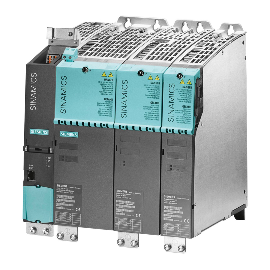
Page 179: Motor Modules
Motor Modules Description A Motor Module is a power unit (DC-AC inverter) that provides the power supply for the motor connected to it. Power is supplied by means of the DC link of the drive unit. A Motor Module must be connected to a Control Unit via DRIVE-CLiQ. The open-loop and closed-loop control functions are stored in the Control Unit. - Page 180 Motor Modules 4.1 Description Operating principle Motor Modules are designed for multi-axis drive systems and are controlled by either a CU320-2 or a SIMOTION D Control Unit. Motor Modules are interconnected by means of a shared DC busbar. One or more Motor Modules are supplied with energy for the motors via the DC link. Both synchronous and induction motors can be operated.
-
Page 181: Safety Information
Motor Modules 4.2 Safety information Safety information WARNING Dangerous electrical voltage After disconnecting all the supply voltages, a hazardous voltage will be present in all components for another 5 minutes. Work cannot be carried out until this time has elapsed. Before starting work, you should also measure the voltage after the 5 minutes have elapsed. -
Page 182: Interface Description
Motor Modules 4.3 Interface description Interface description 4.3.1 Overview Figure 4-1 Motor Module, frame size FX Chassis power units Manual, (GH3), 01/2013, 6SL3097-4AE00-0BP3... - Page 183 Motor Modules 4.3 Interface description Figure 4-2 Motor Module, frame size GX Chassis power units Manual, (GH3), 01/2013, 6SL3097-4AE00-0BP3...
- Page 184 Motor Modules 4.3 Interface description Figure 4-3 Motor Module, frame size HX Chassis power units Manual, (GH3), 01/2013, 6SL3097-4AE00-0BP3...
- Page 185 Motor Modules 4.3 Interface description Figure 4-4 Motor Module, frame size JX Chassis power units Manual, (GH3), 01/2013, 6SL3097-4AE00-0BP3...
-
Page 186: Connection Example
Motor Modules 4.3 Interface description 4.3.2 Connection example Figure 4-5 Connection example Motor Modules Chassis power units Manual, (GH3), 01/2013, 6SL3097-4AE00-0BP3... -
Page 187: Dc Link/Motor Connection
Motor Modules 4.3 Interface description 4.3.3 DC link/motor connection Table 4- 2 DC link/motor connection of the Motor Module Terminals Technical specifications DCP, DCN Voltage: DC power input 510 ... 750 V DC • 675 ... 1080 V DC • Connections: Frame sizes FX / GX: Thread M10 / 25 Nm for cable lugs in accordance with DIN 46234 / •... -
Page 188: X9 Terminal Strip
Motor Modules 4.3 Interface description 4.3.4 X9 terminal strip Table 4- 3 Terminal strip X9 Terminal Signal name Technical specifications P24V Voltage: 24 V DC (20.4 ... 28.8 V) Current consumption: max. 1.4 A 240 V AC: 8 A max. 24 V DC: max. -
Page 189: X41 Ep Terminal / Temperature Sensor Connection
Motor Modules 4.3 Interface description 4.3.6 X41 EP terminal / temperature sensor connection Table 4- 5 Terminal strip X41 Terminal Function Technical specifications EP M1 (Enable Pulses) Supply voltage: 24 VDC (20.4 ... 28.8 V) Current consumption: 10 mA EP +24 V (Enable Pulses) Signal propagation delay times: L →... -
Page 190: X42 Terminal Strip
Motor Modules 4.3 Interface description Note EP terminals only for Safety Integrated Basic Functions The function of the EP terminals is only available when Safety Integrated Basic Functions are enabled. 4.3.7 X42 terminal strip Table 4- 6 Terminal strip X42 voltage supply for Control Unit, Sensor Module and Terminal Module Terminal Function Technical specifications... -
Page 191: Drive-Cliq Interfaces X400, X401, X402
Motor Modules 4.3 Interface description 4.3.9 DRIVE-CLiQ interfaces X400, X401, X402 Table 4- 8 DRIVE-CLiQ interfaces X400, X401, X402 Signal name Technical specifications Transmit data + Transmit data - Receive data + Reserved, do not use Reserved, do not use Receive data - Reserved, do not use Reserved, do not use... -
Page 192: Meaning Of The Leds On The Control Interface Module In The Motor Module
Flashing There is a fault. If the LED continues to flash after you have performed a light POWER ON, please contact your Siemens service center. WARNING Hazardous DC-link voltage Irrespective of the state of the LED "DC LINK", hazardous DC-link voltages can always be present. -
Page 193: Dimension Drawing
Motor Modules 4.4 Dimension drawing Dimension drawing Dimension drawing, frame size FX The mandatory cooling clearances are indicated by the dotted line. Figure 4-6 Dimension drawing Motor Module, frame size FX Front view, side view Chassis power units Manual, (GH3), 01/2013, 6SL3097-4AE00-0BP3... - Page 194 Motor Modules 4.4 Dimension drawing Dimension drawing, frame size GX The mandatory cooling clearances are indicated by the dotted line. Figure 4-7 Dimension drawing Motor Module, frame size GX Front view, side view Chassis power units Manual, (GH3), 01/2013, 6SL3097-4AE00-0BP3...
- Page 195 Motor Modules 4.4 Dimension drawing Dimension drawing, frame size HX The mandatory cooling clearances are indicated by the dotted line. Figure 4-8 Dimension drawing Motor Module, frame size HX Side view, rear view Chassis power units Manual, (GH3), 01/2013, 6SL3097-4AE00-0BP3...
- Page 196 Motor Modules 4.4 Dimension drawing Dimension drawing, frame size JX The mandatory cooling clearances are indicated by the dotted line. Figure 4-9 Dimension drawing Motor Module, frame size JX Side view, rear view Chassis power units Manual, (GH3), 01/2013, 6SL3097-4AE00-0BP3...
-
Page 197: Electrical Connection
Motor Modules 4.5 Electrical connection Electrical connection Adjusting the fan voltage (-T10) The power supply for the device fans (1 AC 230 V) in the Motor Module (-T10) is taken from the line supply using transformers. The installation position of the transformers is indicated in the interface descriptions. - Page 198 Motor Modules 4.5 Electrical connection Table 4- 11 Line voltage assignment for the setting at the fan transformer (3 AC 380 ... 480 V) Line voltage Tap at the fan transformer (-T10) 380 V ± 10% 380 V 400 V ± 10% 400 V 440 V ±...
-
Page 199: Technical Specifications
Motor Modules 4.6 Technical specifications Technical specifications 4.6.1 510 V DC – 750 V DC Motor Modules Table 4- 13 Technical data for Motor Modules, 510 ... 750 VDC, Part 1 Order number 6SL3320– 1TE32–1AA3 1TE32–6AA3 1TE33–1AA3 1TE33–8AA3 Output current - Rated current I - Base load current I - Base load current I... - Page 200 Motor Modules 4.6 Technical specifications Order number 6SL3320– 1TE32–1AA3 1TE32–6AA3 1TE33–1AA3 1TE33–8AA3 Connections - DC-link connection - Motor connection - PE connection PE1 - PE connection PE2 Max. conductor cross-sections - DC-link connection (DCP, DCN) mm² 2 x 185 2 x 185 2 x 240 2 x 240 - Motor connection (U2, V2, W2)
- Page 201 Motor Modules 4.6 Technical specifications Table 4- 14 Technical data for Motor Modules, 510 ... 750 VDC, Part 2 Order number 6SL3320– 1TE35–0AA3 1TE36–1AA3 1TE37–5AA3 1TE38–4AA3 Output current - Rated current I - Base load current I - Base load current I - For S6 operation (40%) I - Max.
- Page 202 Motor Modules 4.6 Technical specifications Order number 6SL3320– 1TE35–0AA3 1TE36–1AA3 1TE37–5AA3 1TE38–4AA3 Max. conductor cross-sections - DC-link connection (DCP, DCN) mm² 2 x 240 Busbar Busbar Busbar - Motor connection (U2, V2, W2) mm² 2 x 240 4 x 240 4 x 240 4 x 240 - PE connection PE1...
- Page 203 Motor Modules 4.6 Technical specifications Table 4- 15 Technical data for Motor Modules, 510 ... 750 VDC, Part 3 Order number 6SL3320– 1TE41–0AA3 1TE41–2AA3 1TE41–4AA3 Output current - Rated current I 1260 1405 - Base load current I 1230 1370 - Base load current I 1127 1257...
- Page 204 Motor Modules 4.6 Technical specifications Order number 6SL3320– 1TE41–0AA3 1TE41–2AA3 1TE41–4AA3 Max. conductor cross-sections - DC-link connection (DCP, DCN) mm² Busbar Busbar Busbar - Motor connection (U2, V2, W2) mm² 6 x 240 6 x 240 6 x 240 - PE connection PE1 mm²...
-
Page 205: Dc - 1080 V Dc Motor Modules
Motor Modules 4.6 Technical specifications 4.6.2 675 V DC – 1080 V DC Motor Modules Table 4- 16 Technical data for Motor Modules, 675 ... 1080 VDC, Part 1 Order number 6SL3320– 1TG28–5AA3 1TG31–0AA3 1TG31–2AA3 1TG31–5AA3 Output current - Rated current I - Base load current I - Base load current I - Max. - Page 206 Motor Modules 4.6 Technical specifications Order number 6SL3320– 1TG28–5AA3 1TG31–0AA3 1TG31–2AA3 1TG31–5AA3 Connections - DC-link connection - Motor connection - PE connection PE1 - PE connection PE2 Max. conductor cross-sections - DC-link connection (DCP, DCN) mm² 2 x 185 2 x 185 2 x 185 2 x 185 - Motor connection (U2, V2, W2)
- Page 207 Motor Modules 4.6 Technical specifications Table 4- 17 Technical data for Motor Modules, 675 ... 1080 VDC, Part 2 Order number 6SL3320– 1TG31–8AA3 1TG32–2AA3 1TG32–6AA3 1TG33–3AA3 Output current - Rated current I - Base load current I - Base load current I - Max.
- Page 208 Motor Modules 4.6 Technical specifications Order number 6SL3320– 1TG31–8AA3 1TG32–2AA3 1TG32–6AA3 1TG33–3AA3 Max. conductor cross-sections - DC-link connection (DCP, DCN) mm² 2 x 240 2 x 240 2 x 240 2 x 240 - Motor connection (U2, V2, W2) mm² 2 x 240 2 x 240 2 x 240...
- Page 209 Motor Modules 4.6 Technical specifications Table 4- 18 Technical data for Motor Modules, 675 ... 1080 VDC, Part 3 Order number 6SL3320– 1TG34–1AA3 1TG34–7AA3 1TG35–8AA3 1TG37–4AA3 Output current - Rated current I - Base load current I - Base load current I - Max.
- Page 210 Motor Modules 4.6 Technical specifications Order number 6SL3320– 1TG34–1AA3 1TG34–7AA3 1TG35–8AA3 1TG37–4AA3 Max. conductor cross-sections - DC-link connection (DCP, DCN) mm² Busbar Busbar Busbar Busbar - Motor connection (U2, V2, W2) mm² 4 x 240 4 x 240 4 x 240 6 x 240 - PE connection PE1 mm²...
- Page 211 Motor Modules 4.6 Technical specifications Table 4- 19 Technical data for Motor Modules, 675 ... 1080 VDC, Part 4 Order number 6SL3320– 1TG38–1AA3 1TG38–8AA3 1TG41–0AA3 1TG41–3AA3 Output current - Rated current I 1025 1270 - Base load current I 1000 1230 - Base load current I 1136...
-
Page 212: Specifications
Motor Modules 4.6 Technical specifications Order number 6SL3320– 1TG38–1AA3 1TG38–8AA3 1TG41–0AA3 1TG41–3AA3 Max. conductor cross-sections - DC-link connection (DCP, DCN) mm² Busbar Busbar Busbar Busbar - Motor connection (U2, V2, W2) mm² 6 x 240 6 x 240 6 x 240 6 x 240 - PE connection PE1 mm²... -
Page 213: Low Overload
Motor Modules 4.6 Technical specifications Low overload The base load current for low overload (I ) is based on a load duty cycle of 110% for 60 s or 150% for 10 s. Figure 4-11 Low overload High overload The base load current for a high overload I is based on a duty cycle of 150% for 60 s or 160% for 10 s. -
Page 214: Current De-Rating Depending On The Pulse Frequency
Motor Modules 4.6 Technical specifications 4.6.4 Current de-rating depending on the pulse frequency When the pulse frequency is increased, the derating factor of the output current must be taken into account. This derating factor must be applied to the currents specified in the technical data for Motor Modules. - Page 215 Motor Modules 4.6 Technical specifications Note Derating factors for pulse frequencies in the range between two fixed values For pulse frequencies in the range between the specified fixed values, the relevant derating factors can be determined by linear interpolation. Maximum output frequencies achieved by increasing the pulse frequency By multiplying the rated pulse frequency with a multiple integer, the following output frequencies can be achieved taking into account the derating factors: Table 4- 22...
-
Page 216: Parallel Connection Of Motor Modules
Motor Modules 4.6 Technical specifications 4.6.5 Parallel connection of Motor Modules The following rules must be observed when connecting Motor Modules in parallel: ● Up to four identical Motor Modules can be connected in parallel. ● A common Control Unit is required whenever the modules are connected in parallel. ●... - Page 217 Motor Modules 4.6 Technical specifications Table 4- 24 Motor Modules, 510 to 750 VDC Order number Type rating Output current Minimum cable length [kW] 6SL3320-1TE32-1AAx 6SL3320-1TE32-6AAx 6SL3320-1TE33-1AAx 6SL3320-1TE33-8AAx 6SL3320-1TE35-0AAx 6SL3320-1TE36-1AAx 6SL3320-1TE37-5AAx 6SL3320-1TE38-4AAx 6SL3320-1TE41-0AAx 6SL3320-1TE41-2AAx 1260 6SL3320-1TE41-4AAx 1405 Table 4- 25 Motor Modules, 675 to 1080 VDC Order number Type rating...
- Page 218 Motor Modules 4.6 Technical specifications Chassis power units Manual, (GH3), 01/2013, 6SL3097-4AE00-0BP3...
-
Page 219: Dc Link Components
DC link components Braking Module 5.1.1 Description A Braking Module and an external braking resistor are required to bring drives to a controlled standstill in the event of a power failure (e.g. emergency retraction or EMERGENCY STOP category 1) or limit the DC-link voltage if the generator is operated for a short period of time, for example because there is no regenerative feedback capability into the supply network when a Basic Line Module is used. - Page 220 DC link components 5.1 Braking Module Layout The Braking Module in chassis format is inserted in a mounting location inside the Basic Line Modules, Smart Line Modules, Active Line Modules, or Motor Modules, the fan of which ensures forced cooling. The supply voltage for the electronics is drawn from the DC link. The Braking Module is connected to the DC link by means of the busbar sets and flexible cables, which are supplied as standard.
-
Page 221: Safety Information
• Route the cables in separate cable ducts or pipes. Note Use only released braking resistors If braking resistors are used that have not been released by SIEMENS for SINAMICS, then the braking resistors could be destroyed. Chassis power units... -
Page 222: Interface Description
DC link components 5.1 Braking Module 5.1.3 Interface description 5.1.3.1 Braking Module for frame sizes FX, FB Figure 5-2 Braking Module for Active Line Module / Motor Module, frame size FX and for Basic Line Module, frame size FB Note Common connection for the R1 and DCPA With this Braking Module, the R1 and DCPA interfaces use the same connection. -
Page 223: Braking Module For Frame Sizes Gx, Gb, Gd
DC link components 5.1 Braking Module 5.1.3.2 Braking Module for frame sizes GX, GB, GD Figure 5-3 Braking Module for Smart Line Module / Active Line Module / Motor Module, frame size GX and for Basic Line Module, frame size GB, GD Note Common connection for the R1 and DCPA With this Braking Module, the R1 and DCPA interfaces use the same connection. -
Page 224: Braking Module For Frame Sizes Hx, Jx
DC link components 5.1 Braking Module 5.1.3.3 Braking Module for frame sizes HX, JX Figure 5-4 Braking Module for Smart Line Module / Active Line Module / Motor Module, frame sizes HX / JX Chassis power units Manual, (GH3), 01/2013, 6SL3097-4AE00-0BP3... -
Page 225: Connection Example
DC link components 5.1 Braking Module 5.1.3.4 Connection example Figure 5-5 Connection example for Braking Module 5.1.3.5 Braking resistor connection Table 5- 1 Braking resistor connection Terminal Designation Braking resistor connection R+ Braking resistor connection R- Recommended conductor cross-sections: for 25/125 kW: 35 mm , for 50/250 kW: 50 mm Chassis power units Manual, (GH3), 01/2013, 6SL3097-4AE00-0BP3... -
Page 226: X21 Digital Inputs/Outputs
Applying a high signal to terminal X21.3 inhibits the Braking Module. On a falling edge, pending error signals are acknowledged. Note Notes on setting You will find setting instructions for wiring the signals in the SINAMICS S120 Function Manual. Chassis power units Manual, (GH3), 01/2013, 6SL3097-4AE00-0BP3... -
Page 227: S1 Threshold Switch
DC link components 5.1 Braking Module 5.1.3.7 S1 Threshold switch The response threshold at which the Braking Module is activated and the DC-link voltage generated during braking are specified in the following table. WARNING Actuate threshold switch only when device is turned off The threshold switch must only be used when the Basic Line, Smart Line, Active Line, or Motor Module are switched off and the DC-link capacitors are discharged. - Page 228 DC link components 5.1 Braking Module Note Positions of the threshold switches The switch positions of the threshold switches of the Braking Modules are positioned on the panel as follows: • Braking Modules for frame sizes FX, FB, GX, GB, GD: Position "1" is at the top; position "2"...
-
Page 229: Installation
DC link components 5.1 Braking Module 5.1.4 Installation 5.1.4.1 Installing the Braking Module in an Active Line Module / Motor Module, frame size FX Figure 5-6 Installing the Braking Module in an Active Line Module / Motor Module, frame size FX – steps 1 - 3 Chassis power units Manual, (GH3), 01/2013, 6SL3097-4AE00-0BP3... - Page 230 DC link components 5.1 Braking Module Figure 5-7 Installing the Braking Module in an Active Line Module / Motor Module, frame size FX – steps 4 - 7 Installing the Braking Module The steps for the installation procedure are numbered in accordance with the diagrams in front of them.
- Page 231 DC link components 5.1 Braking Module 4. Unscrew the three screws of the blanking plate. Remove the plate. 5. Insert the Braking Module where the cover used to be and secure it using the three screws (from step 4). 6. Attach the adapter bar to the DCNA using a nut, so that the busbar cannot be twisted. For this purpose, a small bolt is attached to the adapter bar, which must be located on the lower side of the DCNA connection.
-
Page 232: Installing The Braking Module In A Smart Line Module / Active Line Module / Motor Module, Frame Size Gx
DC link components 5.1 Braking Module 5.1.4.2 Installing the Braking Module in a Smart Line Module / Active Line Module / Motor Module, frame size GX Figure 5-8 Installing the Braking Module in a Smart Line Module / Active Line Module / Motor Module, frame size GX –... - Page 233 DC link components 5.1 Braking Module Figure 5-9 Installing the Braking Module in a Smart Line Module / Active Line Module / Motor Module, frame size GX – steps 4 - 6 Installing the Braking Module The steps for the installation procedure are numbered in accordance with the diagrams in front of them.
- Page 234 DC link components 5.1 Braking Module 4. Unscrew the three screws of the blanking plate. Remove the plate. 5. Insert the Braking Module where the cover used to be and secure it using the three screws (from step 4). 6. Secure the connecting cable to the DC link with two screws (Braking Module connection) and two nuts (DC-link connection).
-
Page 235: Installing The Braking Module In A Smart Line Module / Active Line Module / Motor Module, Frame Size Hx
DC link components 5.1 Braking Module 5.1.4.3 Installing the Braking Module in a Smart Line Module / Active Line Module / Motor Module, frame size HX Figure 5-10 Installing the Braking Module in a Smart Line Module / Active Line Module / Motor Module, frame size HX Installing the Braking Module The steps for the installation procedure are numbered in accordance with the diagram. -
Page 236: Installing The Braking Module In A Smart Line Module / Active Line Module / Motor Module, Frame Size Jx
DC link components 5.1 Braking Module 5.1.4.4 Installing the Braking Module in a Smart Line Module / Active Line Module / Motor Module, frame size JX Figure 5-11 Installing the Braking Module in a Smart Line Module / Active Line Module / Motor Module, frame size JX Installing the Braking Module The steps for the installation procedure are numbered in accordance with the diagram. -
Page 237: Installing The Braking Module In A Basic Line Module, Frame Size Fb
DC link components 5.1 Braking Module 5.1.4.5 Installing the Braking Module in a Basic Line Module, frame size FB Figure 5-12 Installing the Braking Module in a Basic Line Module, frame size FB Chassis power units Manual, (GH3), 01/2013, 6SL3097-4AE00-0BP3... - Page 238 DC link components 5.1 Braking Module Installing the Braking Module The steps for the installation procedure are numbered in accordance with the diagram. 1. Unscrew the three screws of the blanking plate. Remove the plate. 2. Insert the Braking Module where the cover used to be and secure it using the three screws (from step 1).
-
Page 239: Installing The Braking Module In A Basic Line Module, Frame Size Gb, Gd
DC link components 5.1 Braking Module 5.1.4.6 Installing the Braking Module in a Basic Line Module, frame size GB, GD Figure 5-13 Installing the Braking Module in a Basic Line Module, frame size GB, GD Chassis power units Manual, (GH3), 01/2013, 6SL3097-4AE00-0BP3... - Page 240 DC link components 5.1 Braking Module Installing the Braking Module Note To install a frame size GX Braking Module in a frame size GB or GD Basic Line Module a cable harness set is required, which is available under order number 6SL3366-2NG00-0AA0. The steps for the installation procedure are numbered in accordance with the diagram.
-
Page 241: Technical Specifications
DC link components 5.1 Braking Module 5.1.5 Technical specifications Table 5- 4 Technical data, Braking Modules, 3 AC 380 V ... 480 V Braking Module 6SL3300- 1AE31-3AA0 1AE32-5AA0 1AE32-5BA0 Suitable for installation in: Smart Line Module / Active Line Module / Motor Module, frame size HX / JX Basic Line Module, frame size... - Page 242 DC link components 5.1 Braking Module Table 5- 5 Technical data, Braking Modules, 3 AC 500 V ... 600 V Braking Module 6SL3300- 1AF31-3AA0 1AF32-5AA0 1AF32-5BA0 Suitable for installation in: Smart Line Module / Active Line Module / Motor Module, frame size HX / JX Basic Line Module, frame size GB, GD...
- Page 243 DC link components 5.1 Braking Module Table 5- 6 Technical data, Braking Modules, 3 AC 660 V ... 690 V Braking Module 6SL3300- 1AH31-3AA0 1AH32-5AA0 1AH32-5BA0 Suitable for installation in: Smart Line Module / Active Line Module / Motor Module, frame size HX / JX Basic Line Module, frame size GB, GD...
-
Page 244: Braking Resistors
DC link components 5.2 Braking resistors Braking resistors 5.2.1 Description The excess energy of the DC link is dissipated via the braking resistor. The braking resistor is connected to a Braking Module. The braking resistor is positioned outside the cabinet unit or switchgear room. This enables the resulting heat loss around the Basic Line Modules, Smart Line Modules, Active Line Modules, or Motor Modules to be dissipated. -
Page 245: Safety Information
DC link components 5.2 Braking resistors 5.2.2 Safety information NOTICE Maintain ventilation clearances A ventilation clearance of 200 m must be maintained on all sides of the component (with ventilation meshes). WARNING Risk of fire and damage to equipment due to short-circuit / ground fault The cables to the braking resistor must be routed so that a ground fault or short-circuit can be ruled out. -
Page 246: Dimension Drawing
DC link components 5.2 Braking resistors 5.2.3 Dimension drawing Figure 5-14 Dimension drawing braking resistor 25 kW/125 kW Figure 5-15 Dimension drawing braking resistor 50 kW/250 kW Chassis power units Manual, (GH3), 01/2013, 6SL3097-4AE00-0BP3... -
Page 247: Electrical Connection
DC link components 5.2 Braking resistors 5.2.4 Electrical connection WARNING Connect only when the device is switched off The Braking Module must only be connected when the Line Module or Motor Module has been disconnected from the power supply and the DC-link capacitors have been discharged. -
Page 248: Technical Data
DC link components 5.2 Braking resistors 5.2.5 Technical data Table 5- 8 Technical data, braking resistors, 380 V ... 480 V 3 AC Order number Unit 6SL3000-1BE31-3AA0 6SL3000-1BE32-5AA0 (rated power) (peak power) Max. current Resistance Ω 4.4 (± 7,5 %) 2.2 (±... - Page 249 DC link components 5.2 Braking resistors Duty cycle Figure 5-16 Duty cycle for braking resistors Chassis power units Manual, (GH3), 01/2013, 6SL3097-4AE00-0BP3...
- Page 250 DC link components 5.2 Braking resistors Chassis power units Manual, (GH3), 01/2013, 6SL3097-4AE00-0BP3...
-
Page 251: Motor-Side Power Components
Motor-side power components Sine-wave filter 6.1.1 Description If a sine-wave filter is connected to the output of the Motor Module, the voltage between the motor terminals is virtually sinusoidal. This reduces the voltage load on the motor windings and prevents motor noise that would be induced by the pulse frequency. Sine-wave filters are available up to a converter type power rating of 250 kW (without consideration for derating). -
Page 252: Safety Information
• Outgoing cable to the load 1U2, 1V2, 1W2. Non-observance may damage the sine-wave filter. NOTICE Use only approved sine-wave filters If sine-wave filters are used that have not been approved for SINAMICS by SIEMENS, the Motor Modules may be damaged or may malfunction. CAUTION Hot surfaces The surface temperature of the sine-wave filters can exceed 80°... -
Page 253: Dimension Drawing
Motor-side power components 6.1 Sine-wave filter 6.1.3 Dimension drawing Mounting holes Figure 6-2 Dimension drawing, sine-wave filter Chassis power units Manual, (GH3), 01/2013, 6SL3097-4AE00-0BP3... -
Page 254: Technical Data
Motor-side power components 6.1 Sine-wave filter Table 6- 1 Dimensions of the sine-wave filter (all values in mm) 6SL3000- 2CE32-3AA0 2CE32-8AA0 2CE33-3AA0 2CE34-1AA0 The lengths n1, n2 and n3 correspond to the drill hole spacing 6.1.4 Technical data Table 6- 2 Technical data of sine-wave filters 380 V ... -
Page 255: Motor Reactors
The connecting cables to the Motor Module must be kept as short as possible (max. 5 m). NOTICE Use only released motor reactors Using motor reactors not approved by SIEMENS for SINAMICS can result in thermal damage to the reactor. CAUTION Hot surfaces The surface temperature of the motor reactors can exceed 80°... - Page 256 Motor-side power components 6.2 Motor reactors NOTICE Maximum pulse frequency The maximum permissible pulse frequency when motor reactors are used is 2.5 Hz or 4 kHz. Chassis power units Manual, (GH3), 01/2013, 6SL3097-4AE00-0BP3...
-
Page 257: Dimension Drawing
Motor-side power components 6.2 Motor reactors 6.2.3 Dimension drawing Figure 6-3 Dimension drawing, motor reactor Chassis power units Manual, (GH3), 01/2013, 6SL3097-4AE00-0BP3... - Page 258 Motor-side power components 6.2 Motor reactors Table 6- 3 Dimensions of motor reactors, 3 AC 380 V ... 480 V, Part 1 (all specifications in mm) 6SL3000- 2BE32-1AA0 2BE32-6AA0 2BE33-2AA0 2BE33-8AA0 2BE35-0AA0 Connection type Type 1 Type 1 Type 1 Type 1 Type 2 12.5...
- Page 259 Motor-side power components 6.2 Motor reactors Table 6- 5 Dimensions of motor reactors, 3 AC 500 V ... 690 V, Part 1 (all specifications in mm) 6SL3000- 2AH31-0AA0 2AH31-5AA0 2AH31-8AA0 2AH32-4AA0 2AH32-6AA0 Connection type Type 1 Type 1 Type 1 Type 1 Type 1 12.5...
- Page 260 Motor-side power components 6.2 Motor reactors Table 6- 7 Dimensions of motor reactors, 3 AC 500 V ... 690 V, Part 3 (all specifications in mm) 6SL3000- 2AH41-0AA0 2AH41-1AA0 2AH41-3AA0 Connection type Type 1 Type 1 Type 1 79.5 94.5 94.5 Lengths n1 and n2 correspond to the distance between holes Chassis power units...
-
Page 261: Technical Data
Motor-side power components 6.2 Motor reactors 6.2.4 Technical data Table 6- 8 Technical data of motor reactors, 3 AC 380 V ... 480 V, Part 1 Order number 6SL3000- 2BE32-1AA0 2BE32-6AA0 2BE33-2AA0 2BE33-8AA0 Suitable for Motor Module 6SL3320- 1TE32-1AAx 1TE32-6AAx 1TE33-1AAx 1TE33-8AAx Type rating of the Motor Module... - Page 262 Motor-side power components 6.2 Motor reactors Table 6- 10 Technical data of motor reactors, 3 AC 380 ... 480 V, Part 3 Order number 6SL3000- 2AE41-0AA0 2AE41-4AA0 2AE41-4AA0 Suitable for Motor Module 6SL3320- 1TE41-0AAx 1TE41-2AAx 1TE41-4AAx Type rating of the Motor Module Rated current 1405 1405...
- Page 263 Motor-side power components 6.2 Motor reactors Table 6- 12 Technical data of motor reactors, 3 AC 500 ... 690 V, Part 2 Order number 6SL3000- 2AH31-8AA0 2AH32-4AA0 2AH32-6AA0 2AH33-6AA0 Suitable for Motor Module 6SL3320- 1TG31-8AAx 1TG32-2AAx 1TG32-6AAx 1TG33-3AAx Type rating of the Motor Module Rated current Power loss - At 50 Hz...
- Page 264 Motor-side power components 6.2 Motor reactors Table 6- 14 Technical data of motor reactors, 3 AC 500 ... 690 V, Part 4 Order number 6SL3000- 2AH38-1AA0 2AH41-0AA0 2AH41-1AA0 2AH41-3AA0 Suitable for Motor Module 6SL3320- 1TG38-1AAx 1TG38-8AAx 1TG41-0AAx 1TG41-3AAx Type rating of the Motor Module 1000 1200 Rated current...
-
Page 265: Dv/Dt Filter Plus Voltage Peak Limiter
Motor-side power components 6.3 dv/dt filter plus Voltage Peak Limiter dv/dt filter plus Voltage Peak Limiter 6.3.1 Description The dV/dt filter plus voltage peak limiter comprises two components: The dV/dt reactor and the voltage-limiting network (voltage peak limiter) which cuts of the voltage peaks and returns energy to the DC link. - Page 266 Motor-side power components 6.3 dv/dt filter plus Voltage Peak Limiter Table 6- 16 Max. pulse frequency when a dV/dt filter is used in units with a rated pulse frequency of 2 kHz Order no. Power Output current for a Max. pulse frequency when a 6SL3320-...
-
Page 267: Safety Information
Failure to connect the terminals correctly could damage the voltage peak limiter. NOTICE Use only approved dV/dt filters When using dV/dt filters that SIEMENS has not approved for SINAMICS, then these dV/dt filters can be thermally damaged. CAUTION Hot surfaces The surface temperature of the dV/dt reactors may exceed 80°... -
Page 268: Interface Description
Motor-side power components 6.3 dv/dt filter plus Voltage Peak Limiter NOTICE Maximum permissible output frequency The maximum permissible output frequency when using dV/dt filters is 150 Hz. 6.3.3 Interface description Figure 6-4 Interface overview, voltage peak limiter, type 1 Figure 6-5 Interface overview, voltage peak limiter, type 2 Chassis power units Manual, (GH3), 01/2013, 6SL3097-4AE00-0BP3... - Page 269 Motor-side power components 6.3 dv/dt filter plus Voltage Peak Limiter Figure 6-6 Interface overview, voltage peak limiter, type 3 Chassis power units Manual, (GH3), 01/2013, 6SL3097-4AE00-0BP3...
-
Page 270: Connecting The Dv/Dt Filter Plus Voltage Peak Limiter
Motor-side power components 6.3 dv/dt filter plus Voltage Peak Limiter 6.3.4 Connecting the dv/dt filter plus Voltage Peak Limiter Figure 6-7 Connecting a dV/dt filter plus voltage peak limiter for versions with one dV/dt reactor Figure 6-8 Connecting a dV/dt filter plus voltage peak limiter for versions with two dV/dt reactors Chassis power units Manual, (GH3), 01/2013, 6SL3097-4AE00-0BP3... - Page 271 Motor-side power components 6.3 dv/dt filter plus Voltage Peak Limiter Cable cross-sections Table 6- 18 Cable cross-sections for connections between the dV/dt filter plus voltage peak limiter and Motor Module dV/dt filter plus voltage Connection to the DC link Connection between dV/dt reactor and peak limiter (DCPS/DCNS) voltage peak limiter...
-
Page 272: Dimension Drawing, Dv/Dt Reactor
Motor-side power components 6.3 dv/dt filter plus Voltage Peak Limiter 6.3.5 Dimension drawing, dv/dt reactor Figure 6-9 Dimension drawing, dV/dt reactor Chassis power units Manual, (GH3), 01/2013, 6SL3097-4AE00-0BP3... - Page 273 Motor-side power components 6.3 dv/dt filter plus Voltage Peak Limiter Table 6- 19 Dimensions of dV/dt reactor, 380 V ... 480 V 3 AC (all dimensions in mm) 6SL3000- 2DE32-6CA0 2DE35-0CA0 2DE38-4CA0 2DE41-4DA0 10.5 x 14 14 x 18 14 x 18 14 x 18 152.5 152.5...
- Page 274 Motor-side power components 6.3 dv/dt filter plus Voltage Peak Limiter Table 6- 21 Dimensions of dV/dt reactor, 500 V ... 690 V 3 AC, part 2 (all dimensions in mm) 6SL3000- 2DH35-8CA0 2DH38-1DA0 2DH41-3DA0 14 x 18 14 x 18 14 x 18 152.5 hmax...
-
Page 275: Dimension Drawing Of The Voltage Peak Limiter
Motor-side power components 6.3 dv/dt filter plus Voltage Peak Limiter 6.3.6 Dimension drawing of the Voltage Peak Limiter Figure 6-10 Dimension drawing of the voltage peak limiter, type 1 Figure 6-11 Dimension drawing of the voltage peak limiter, type 2 Chassis power units Manual, (GH3), 01/2013, 6SL3097-4AE00-0BP3... - Page 276 Motor-side power components 6.3 dv/dt filter plus Voltage Peak Limiter Figure 6-12 Dimension drawing of the voltage peak limiter, type 3 Chassis power units Manual, (GH3), 01/2013, 6SL3097-4AE00-0BP3...
- Page 277 Motor-side power components 6.3 dv/dt filter plus Voltage Peak Limiter Table 6- 22 Assigning voltage peak limiter to dimension drawings Voltage peak limiter Dimension drawing type 380 ... 480 V line voltage 6SL3000-2DE32-6BA0 Type 1 6SL3000-2DE35-0BA0 Type 2 6SL3000-2DE38-4BA0 Type 3 6SL3000-2DE41-4BA0 Type 3 500 ...
-
Page 278: Technical Data
Motor-side power components 6.3 dv/dt filter plus Voltage Peak Limiter 6.3.7 Technical data Table 6- 23 Technical data of the dV/dt filter plus voltage peak limiter, 3 AC 380 ... 480 V, Part 1 Order number 6SL3000- 2DE32-6AA0 2DE32-6AA0 2DE35-0AA0 2DE35-0AA0 Suitable for Motor Module 6SL3320-... - Page 279 Motor-side power components 6.3 dv/dt filter plus Voltage Peak Limiter Table 6- 24 Technical data of the dV/dt filter plus voltage peak limiter, 3 AC 380 ... 480 V, Part 2 Order number 6SL3000- 2DE35-0AA0 2DE38-4AA0 2DE38-4AA0 2DE38-4AA0 Suitable for Motor Module 6SL3320- 1TE35-0AAx 1TE36-1AAx...
- Page 280 Motor-side power components 6.3 dv/dt filter plus Voltage Peak Limiter Table 6- 25 Technical data of the dV/dt filter plus voltage peak limiter, 3 AC 380 ... 480 V, Part 3 Order number 6SL3000- 2DE41-4AA0 2DE41-4AA0 2DE41-4AA0 Suitable for Motor Module 6SL3320- 1TE41-0AAx 1TE41-2AAx...
- Page 281 Motor-side power components 6.3 dv/dt filter plus Voltage Peak Limiter Table 6- 26 Technical data of the dV/dt filter plus voltage peak limiter, 3 AC 500 ... 690 V, Part 1 Order number 6SL3000- 2DH31-0AA0 2DH31-0AA0 2DH31-5AA0 2DH31-5AA0 Suitable for Motor Module 6SL3320- 1TG28-5AAx 1TG31-0AAx...
- Page 282 Motor-side power components 6.3 dv/dt filter plus Voltage Peak Limiter Table 6- 27 Technical data of the dV/dt filter plus voltage peak limiter, 3 AC 500 ... 690 V, Part 2 Order number 6SL3000- 2DH32-2AA0 2DH32-2AA0 2DH33-3AA0 2DH33-3AA0 Suitable for Motor Module 6SL3320- 1TG31-8AAx 1TG32-2AAx...
- Page 283 Motor-side power components 6.3 dv/dt filter plus Voltage Peak Limiter Table 6- 28 Technical data of the dV/dt filter plus voltage peak limiter, 3 AC 500 ... 690 V, Part 3 Order number 6SL3000- 2DH34-1AA0 2DH35-8AA0 2DH35-8AA0 2DH38-1AA0 Suitable for Motor Module 6SL3320- 1TG34-1AAx 1TG34-7AAx...
- Page 284 Motor-side power components 6.3 dv/dt filter plus Voltage Peak Limiter Table 6- 29 Technical data of the dV/dt filter plus voltage peak limiter, 3 AC 500 ... 690 V, Part 4 Order number 6SL3000- 2DH38-1AA0 2DH41-3AA0 2DH41-3AA0 2DH41-3AA0 Suitable for Motor Module 6SL3320- 1TG38-1AAx 1TG38-8AAx...
-
Page 285: Dv/Dt Filter Compact Plus Voltage Peak Limiter
Motor-side power components 6.4 dv/dt filter compact plus Voltage Peak Limiter dv/dt filter compact plus Voltage Peak Limiter 6.4.1 Description The dV/dt filter compact plus voltage peak limiter comprises two components: The dV/dt reactor and the voltage-limiting network (voltage peak limiter) which cuts off the voltage peaks and feeds back the energy into the DC link. - Page 286 Motor-side power components 6.4 dv/dt filter compact plus Voltage Peak Limiter Note Components of the dV/dt filter The dV/dt filters compact plus voltage peak limiter of types 1 to 3 consist of a single component. Type 4 consists of two separate components, the dV/dt reactor and the voltage peak limiter.
- Page 287 Motor-side power components 6.4 dv/dt filter compact plus Voltage Peak Limiter Table 6- 31 Max. pulse frequency when a dV/dt filter compact plus voltage peak limiter is used in units with a rated pulse frequency of 1.25 kHz Order no. of the Type rating Output current for a Max.
-
Page 288: Safety Information
Failure to connect the terminals correctly could damage the voltage peak limiter. NOTICE Use only approved dV/dt filters When using dV/dt filters that SIEMENS has not approved for SINAMICS, then these dV/dt filters can be thermally damaged. CAUTION Hot surfaces The surface temperature of the dV/dt filters compact may exceed 80°... -
Page 289: Interface Description
Motor-side power components 6.4 dv/dt filter compact plus Voltage Peak Limiter NOTICE No operation without connected motor When a dV/dt filter compact plus voltage peak limiter is used, the drive must not be operated without a connected motor, otherwise the filter could be destroyed. NOTICE Maximum permissible output frequency The maximum permissible output frequency when using dV/dt filters compact plus voltage... - Page 290 Motor-side power components 6.4 dv/dt filter compact plus Voltage Peak Limiter Figure 6-14 Interface overview for dv/dt filter compact plus Voltage Peak Limiter, Type 2 Figure 6-15 Interface overview for dv/dt filter compact plus Voltage Peak Limiter, Type 3 Chassis power units Manual, (GH3), 01/2013, 6SL3097-4AE00-0BP3...
- Page 291 Motor-side power components 6.4 dv/dt filter compact plus Voltage Peak Limiter Figure 6-16 Interface overview for dv/dt filter compact plus Voltage Peak Limiter, Type 4 dv/dt reactor Chassis power units Manual, (GH3), 01/2013, 6SL3097-4AE00-0BP3...
-
Page 292: Connecting The Dv/Dt Filter Compact Plus Voltage Peak Limiter
Motor-side power components 6.4 dv/dt filter compact plus Voltage Peak Limiter Figure 6-17 Interface overview for dv/dt filter compact plus Voltage Peak Limiter, Type 4 Voltage Peak Limiter 6.4.4 Connecting the dv/dt filter compact plus Voltage Peak Limiter Figure 6-18 Connecting the dV/dt filter compact plus voltage peak limiter - integrated unit Chassis power units Manual, (GH3), 01/2013, 6SL3097-4AE00-0BP3... - Page 293 Motor-side power components 6.4 dv/dt filter compact plus Voltage Peak Limiter Figure 6-19 Connecting the dV/dt filter compact plus voltage peak limiter - separate components Cable cross-sections In a dV/dt filter with separate voltage peak limiter (type 4), the connections between dV/dt reactor and voltage peak limiter are already installed on the voltage peak limiter.
- Page 294 Motor-side power components 6.4 dv/dt filter compact plus Voltage Peak Limiter WARNING Risk of fire and damage to equipment due to short-circuit / ground fault The cables to the DC link of the Motor Modules must be routed so that a ground fault or short-circuit can be ruled out.
-
Page 295: Dimension Drawing For Dv/Dt Filter Compact Plus Voltage Peak Limiter
Motor-side power components 6.4 dv/dt filter compact plus Voltage Peak Limiter 6.4.5 Dimension drawing for dv/dt filter compact plus Voltage Peak Limiter dV/dt filter compact plus voltage peak limiter, type 1 Figure 6-20 Dimension drawing for dV/dt filter compact plus voltage peak limiter, type 1 Chassis power units Manual, (GH3), 01/2013, 6SL3097-4AE00-0BP3... - Page 296 Motor-side power components 6.4 dv/dt filter compact plus Voltage Peak Limiter dV/dt filter compact plus voltage peak limiter, type 2 Figure 6-21 Dimension drawing for dV/dt filter compact plus voltage peak limiter, type 2 Chassis power units Manual, (GH3), 01/2013, 6SL3097-4AE00-0BP3...
- Page 297 Motor-side power components 6.4 dv/dt filter compact plus Voltage Peak Limiter dV/dt filter compact plus voltage peak limiter, type 3 Figure 6-22 Dimension drawing for dV/dt filter compact plus voltage peak limiter, type 3 Chassis power units Manual, (GH3), 01/2013, 6SL3097-4AE00-0BP3...
- Page 298 Motor-side power components 6.4 dv/dt filter compact plus Voltage Peak Limiter dV/dt filter compact plus voltage peak limiter, type 4 Figure 6-23 Dimension drawing for dV/dt filter compact plus voltage peak limiter, type 4 dV/dt reactor Chassis power units Manual, (GH3), 01/2013, 6SL3097-4AE00-0BP3...
- Page 299 Motor-side power components 6.4 dv/dt filter compact plus Voltage Peak Limiter Figure 6-24 Dimension drawing for dV/dt filter compact plus voltage peak limiter, type 4 Voltage peak limiter Chassis power units Manual, (GH3), 01/2013, 6SL3097-4AE00-0BP3...
-
Page 300: Technical Data
Motor-side power components 6.4 dv/dt filter compact plus Voltage Peak Limiter Table 6- 34 Assignment of dV/dt filters compact plus voltage peak limiter to the dimension drawings dV/dt filter compact plus voltage peak limiter Dimension drawing type Line supply voltage 3-ph. 380...480 V AC 6SL3000-2DE32-6EA0 Type 1 6SL3000-2DE35-0EA0... - Page 301 Motor-side power components 6.4 dv/dt filter compact plus Voltage Peak Limiter Table 6- 36 Technical data of the dV/dt filter compact plus voltage peak limiter, 380 V ... 480 V 3 AC, Part 2 Order number 6SL3000- 2DE41-4EA0 Suitable for Motor Module 6SL3320- 1TE41-0AAx (560 kW) (unit rating)
- Page 302 Motor-side power components 6.4 dv/dt filter compact plus Voltage Peak Limiter Table 6- 37 Technical data of the dV/dt filter compact plus voltage peak limiter, 500 V ... 690 V 3 AC, Part 1 Order number 6SL3000- 2DG31-0EA0 2DG31-5EA0 2DG32-2EA0 Suitable for Motor Module 6SL3320- 1TG28-5AAx (75 kW)
- Page 303 Motor-side power components 6.4 dv/dt filter compact plus Voltage Peak Limiter Table 6- 39 Technical data of the dV/dt filter compact plus voltage peak limiter, 500 V ... 690 V 3 AC, Part 3 Order number 6SL3000- 2DG38-1EA0 2DG41-3EA0 Suitable for Motor Module 6SL3320- 1TG37-4AAx (710 kW) 1TG38-8AAx (900 kW)
- Page 304 Motor-side power components 6.4 dv/dt filter compact plus Voltage Peak Limiter Chassis power units Manual, (GH3), 01/2013, 6SL3097-4AE00-0BP3...
-
Page 305: Cabinet Design And Emc
7.1.1 General The modular concept of SINAMICS S120 allows a wide range of potential device combinations. For this reason, it is impossible to describe each individual combination. This section instead aims to provide some basic information and general rules on the basis of which special device combinations can be constructed and to ensure electromagnetic compatibility. - Page 306 Comply with all safety regulations Safety regulations governing shock protection must be observed. See also EN 60204-1. NOTICE Only use original Siemens accessories To ensure that the entire system functions properly, you are advised to use original Siemens accessories. Only original DRIVE-CLiQ cables may be used for wiring the DRIVE-CLiQ nodes.
- Page 307 Cabinet design and EMC 7.1 Information NOTICE Limiting of overvoltages On systems with a grounded phase conductor and a line voltage >600 VAC, line-side components should be installed to limit overvoltages to overvoltage category II according to IEC 61800-5-1. Maximum cable lengths Table 7- 1 Maximum cable lengths Type...
-
Page 308: Insulation Test
Cabinet design and EMC 7.1 Information 7.1.3 Insulation test Insulation test In accordance with EN 60204-1, an insulation test must be performed on the machine/system. The test may be done with one of the following tests: ● Insulation resistance test ●... -
Page 309: Directives
Cabinet design and EMC 7.2 EMC-compliant design and control cabinet configuration Components and devices that have been voltage tested according to their product standard may be disconnected during testing. The SINAMICS components are voltage tested in accordance with EN 61800-5-1 and are to be disconnected during this test. -
Page 310: Cabinet Air Conditioning
NOTICE Avoid the reduction of service life If the guidelines for installing SINAMICS S120 Chassis devices are not observed, this can significantly reduce the service life of the components and result in premature component failure. -
Page 311: Ventilation
7.3.2 Ventilation The SINAMICS S120 Chassis devices are forced-ventilated by means of integrated fans. To ensure an adequate air supply, suitable openings for the inlet air (e.g. ventilation slots in the cabinet door) and discharged air (e.g. by means of a hood) must be provided. - Page 312 Cabinet design and EMC 7.3 Cabinet air conditioning Figure 7-1 Air guidance for Active Interface Module, frame sizes FI, GI Chassis power units Manual, (GH3), 01/2013, 6SL3097-4AE00-0BP3...
- Page 313 Cabinet design and EMC 7.3 Cabinet air conditioning Figure 7-2 Air guidance for Active Interface Module, frame sizes HI, JI Chassis power units Manual, (GH3), 01/2013, 6SL3097-4AE00-0BP3...
- Page 314 Cabinet design and EMC 7.3 Cabinet air conditioning Figure 7-3 Air guidance for Smart Line Module, Active Line Module, Motor Module, frame sizes FX, Chassis power units Manual, (GH3), 01/2013, 6SL3097-4AE00-0BP3...
- Page 315 Cabinet design and EMC 7.3 Cabinet air conditioning Figure 7-4 Air guidance for Smart Line Module, Active Line Module, Motor Module, frame sizes HX, Chassis power units Manual, (GH3), 01/2013, 6SL3097-4AE00-0BP3...
- Page 316 Cabinet design and EMC 7.3 Cabinet air conditioning Figure 7-5 Air guidance for Basic Line Module, frame sizes FB, GB, GD Devices must not be operated in an "air short-circuit", since this can damage equipment or cause it to fail. The drawn air of the fan causes negative pressure to build up at the ventilation openings in the cabinet doors.
- Page 317 Cabinet design and EMC 7.3 Cabinet air conditioning Due to the flow of air within the cabinet, the device fan draws in pre-heated air. This heats up the components considerably and the fan does not function effectively. NOTICE To prevent an air short-circuit Devices must not be operated in an air short-circuit, since this can cause it to fail.
- Page 318 Cabinet design and EMC 7.3 Cabinet air conditioning The opening cross-sections specified in the table refer in each case to one device. If more than one device is installed in a cabinet, the opening cross-section increases accordingly. If the required openings cannot be made in the cabinet, the devices must be distributed across several cabinets which are separated from each other by means of partitions.
- Page 319 Cabinet design and EMC 7.3 Cabinet air conditioning Smart Line Modules Order number 6SL3330- 6TE35-5AAx 6TE41-1AAx 6TE41-3AAx 6TE37-3AAx 6TG38-8AAx 6TE41-7AAx 6TG35-5AAx 6TG41-2AAx 6TG41-7AAx Cooling air requirement [m³/s] 0.36 0.78 1.08 Min. opening cross-section in cabinet inlet outlet [m²] 0.19 0.28 0.38 [m²] 0.19...
- Page 320 Cabinet design and EMC 7.3 Cabinet air conditioning Chassis power units Manual, (GH3), 01/2013, 6SL3097-4AE00-0BP3...
-
Page 321: Maintenance And Servicing
Maintenance and Servicing Chapter content This chapter provides information on the following: ● Maintenance and servicing procedures that have to be carried out on a regular basis to ensure the availability of the components. ● Exchanging device components when the unit is serviced ●... -
Page 322: Maintenance
The actual intervals at which maintenance procedures are to be performed depend on the installation conditions (cabinet environment) and the operating conditions. Siemens offers its customers support in the form of a service contract. For further details, contact your regional office or sales office. - Page 323 Maintenance and Servicing 8.3 Maintenance Tightening torques for screw connections The following tightening torques apply when tightening connections of operating current- conducting parts (DC-link/motor connections, general busbars), non-operating current- conducting parts (ground connections, ground terminal connections), and general steel threaded connections. Table 8- 1 Tightening torques for screw connections Thread...
-
Page 324: Installation Device
Maintenance and Servicing 8.3 Maintenance 8.3.1 Installation device Description The installation device is used for installing and removing the power blocks for the Basic Line Modules, Smart Line Modules, Active Line Modules, and Motor Modules in chassis format. It is used as a mounting aid and is placed in front of and secured to the module. The telescopic rails allow the withdrawable device to be adjusted according to the height at which the power blocks are installed. -
Page 325: Using Crane Lifting Lugs To Transport Power Blocks
Maintenance and Servicing 8.3 Maintenance 8.3.2 Using crane lifting lugs to transport power blocks Crane lifting lugs The power blocks are fitted with crane lifting lugs for transportation on a lifting harness in the context of replacement. The positions of the crane lifting lugs are illustrated by arrows in the figures below. WARNING Hazards during improper transport A lifting harness with vertical ropes or chains must be used to prevent any risk of damage... - Page 326 Maintenance and Servicing 8.3 Maintenance Figure 8-3 Crane lifting lugs on HX, JX power block Note Crane lifting lugs on HX, JX power block On HX and JX power blocks, the front crane lifting lug is located behind the busbar. Chassis power units Manual, (GH3), 01/2013, 6SL3097-4AE00-0BP3...
- Page 327 Maintenance and Servicing 8.3 Maintenance Figure 8-4 Crane lifting lugs on power block frame size GB, GD Chassis power units Manual, (GH3), 01/2013, 6SL3097-4AE00-0BP3...
-
Page 328: Replacing Components
Maintenance and Servicing 8.4 Replacing components Replacing components 8.4.1 Safety information WARNING Hazards during transport and replacement of components When transporting the devices and replacing components, note the following: • Some of the devices and components are heavy (e.g. > 30 Kg) and top heavy. •... -
Page 329: Replacing The Power Block, Active Line Module, And Motor Module, Frame Size Fx
Maintenance and Servicing 8.4 Replacing components 8.4.2 Replacing the power block, Active Line Module, and Motor Module, frame size Replacing the power block Figure 8-5 Replacing the power block, Active Line Module, and Motor Module (type FX) Chassis power units Manual, (GH3), 01/2013, 6SL3097-4AE00-0BP3... - Page 330 Maintenance and Servicing 8.4 Replacing components Preparatory steps ● Disconnect the drive line-up from the power supply ● Allow unimpeded access to the power block ● Remove the front cover Removal The removal steps are numbered in accordance with the numbers in the diagram. 1.
- Page 331 Maintenance and Servicing 8.4 Replacing components Installation steps Installing is the same as removing, however in the reverse order. NOTICE Specifications for the installation The tightening torques specified in the table "Tightening torques for screw connections" must be observed. Carefully insert the plug connections and ensure that they are secure. The fiber optic cable plugs must be remounted at their original slot.
-
Page 332: Replacing The Power Block, Smart Line Module, Active Line Module, And Motor Module, Frame Size Gx
Maintenance and Servicing 8.4 Replacing components 8.4.3 Replacing the power block, Smart Line Module, Active Line Module, and Motor Module, frame size GX Replacing the power block Figure 8-6 Replacing the power block, Smart Line Module, Active Line Module, and Motor Module, frame size GX Chassis power units Manual, (GH3), 01/2013, 6SL3097-4AE00-0BP3... - Page 333 Maintenance and Servicing 8.4 Replacing components Preparatory steps ● Disconnect the drive line-up from the power supply ● Allow unimpeded access to the power block ● Remove the front cover Removal The removal steps are numbered in accordance with the numbers in the diagram. 1.
- Page 334 Maintenance and Servicing 8.4 Replacing components Installation steps Installing is the same as removing, however in the reverse order. NOTICE Caution when removing The tightening torques specified in the table "Tightening torques for screw connections" must be observed. Carefully insert the plug connections and ensure that they are secure. The fiber optic cable plugs must be remounted at their original slot.
-
Page 335: Replacing The Power Block, Smart Line Module, Active Line Module, And Motor Module, Frame Size Hx
Maintenance and Servicing 8.4 Replacing components 8.4.4 Replacing the power block, Smart Line Module, Active Line Module, and Motor Module, frame size HX Replacing the left-hand power block Figure 8-7 Replacing the power block, Smart Line Module, Active Line Module, and Motor Module, frame size HX - left power block Chassis power units Manual, (GH3), 01/2013, 6SL3097-4AE00-0BP3... - Page 336 Maintenance and Servicing 8.4 Replacing components Preparatory steps ● Disconnect the drive line-up from the power supply ● Allow unimpeded access to the power block ● Remove the protective cover Removal The removal steps are numbered in accordance with the numbers in the diagram. 1.
- Page 337 Maintenance and Servicing 8.4 Replacing components Replacing the right-hand power block Figure 8-8 Replacing the power block, Smart Line Module, Active Line Module, and Motor Module, frame size HX - right power block Chassis power units Manual, (GH3), 01/2013, 6SL3097-4AE00-0BP3...
- Page 338 Maintenance and Servicing 8.4 Replacing components Preparatory steps ● Disconnect the drive line-up from the power supply ● Allow unimpeded access to the power block ● Remove the protective cover Removal The removal steps are numbered in accordance with the numbers in the diagram. 1.
- Page 339 Maintenance and Servicing 8.4 Replacing components Installation steps Installing is the same as removing, however in the reverse order. NOTICE Specifications for the installation The tightening torques specified in the table "Tightening torques for screw connections" must be observed. Carefully insert the plug connections and ensure that they are secure. The fiber optic cable plugs must be remounted at their original slot.
-
Page 340: Replacing The Power Block, Smart Line Module, Active Line Module, And Motor Module, Frame Size Jx
Maintenance and Servicing 8.4 Replacing components 8.4.5 Replacing the power block, Smart Line Module, Active Line Module, and Motor Module, frame size JX Replacing the power block Figure 8-9 Replacing the power block, Smart Line Module, Active Line Module, and Motor Module, frame size JX Chassis power units Manual, (GH3), 01/2013, 6SL3097-4AE00-0BP3... - Page 341 Maintenance and Servicing 8.4 Replacing components Preparatory steps ● Disconnect the drive line-up from the power supply ● Allow unimpeded access to the power block ● Remove the protective cover Removal The removal steps are numbered in accordance with the numbers in the diagram. 1.
-
Page 342: Replacing The Power Block, Basic Line Module, Frame Size Fb
Maintenance and Servicing 8.4 Replacing components 8.4.6 Replacing the power block, Basic Line Module, frame size FB Replacing the power block Figure 8-10 Replacing the power block, Basic Line Module, frame size FB Chassis power units Manual, (GH3), 01/2013, 6SL3097-4AE00-0BP3... - Page 343 Maintenance and Servicing 8.4 Replacing components Preparatory steps ● Disconnect the drive line-up from the power supply ● Allow unimpeded access to the power block ● Remove the protective cover Removal The removal steps are numbered in accordance with the numbers in the diagram. 1.
- Page 344 Maintenance and Servicing 8.4 Replacing components Installation steps Installing is the same as removing, however in the reverse order. NOTICE Specifications for the installation The tightening torques specified in the table "Tightening torques for screw connections" must be observed. Carefully insert the plug connections and ensure that they are secure. Note Connection clip for the interference-suppression capacitor The connection clip to the interference suppression capacitor is mounted on the spare power...
-
Page 345: Replacing The Power Block, Basic Line Module Gb, Gd
Maintenance and Servicing 8.4 Replacing components 8.4.7 Replacing the power block, Basic Line Module GB, GD Replacing the power block Figure 8-11 Replacing the power block, Basic Line Module, frame sizes GB, GD Chassis power units Manual, (GH3), 01/2013, 6SL3097-4AE00-0BP3... - Page 346 Maintenance and Servicing 8.4 Replacing components Preparatory steps ● Disconnect the drive line-up from the power supply ● Allow unimpeded access to the power block ● Remove the protective cover Removal The removal steps are numbered in accordance with the numbers in the diagram. 1.
- Page 347 Maintenance and Servicing 8.4 Replacing components Installation steps Installing is the same as removing, however in the reverse order. NOTICE Specifications for the installation The tightening torques specified in the table "Tightening torques for screw connections" must be observed. Carefully insert the plug connections and ensure that they are secure. Note Connection clip for the interference-suppression capacitor The connection clip to the interference suppression capacitor is mounted on the spare power...
-
Page 348: Replacing The Control Interface Module, Active Line Module And Motor Module, Frame Size Fx
Maintenance and Servicing 8.4 Replacing components 8.4.8 Replacing the Control Interface Module, Active Line Module and Motor Module, frame size FX Replacing the Control Interface Module Figure 8-12 Replacing the Control Interface Module, Active Line Module and Motor Module, frame size FX Chassis power units Manual, (GH3), 01/2013, 6SL3097-4AE00-0BP3... - Page 349 Maintenance and Servicing 8.4 Replacing components Preparatory steps ● Disconnect the drive line-up from the power supply ● Allow unimpeded access ● Remove the front cover Removal The removal steps are numbered in accordance with the numbers in the diagram. 1.
-
Page 350: Replacing The Control Interface Module, Smart Line Module, Active Line Module, And Motor Module, Frame Size Gx
Maintenance and Servicing 8.4 Replacing components 8.4.9 Replacing the Control Interface Module, Smart Line Module, Active Line Module, and Motor Module, frame size GX Replacing the Control Interface Module Figure 8-13 Replacing the Control Interface Module, Smart Line Module, Active Line Module, and Motor Module, frame size GX Chassis power units Manual, (GH3), 01/2013, 6SL3097-4AE00-0BP3... - Page 351 Maintenance and Servicing 8.4 Replacing components Preparatory steps ● Disconnect the drive line-up from the power supply ● Allow unimpeded access ● Remove the front cover Removal The removal steps are numbered in accordance with the numbers in the diagram. 1.
-
Page 352: Replacing The Control Interface Module, Smart Line Module, Active Line Module, And Motor Module, Frame Size Hx
Maintenance and Servicing 8.4 Replacing components 8.4.10 Replacing the Control Interface Module, Smart Line Module, Active Line Module, and Motor Module, frame size HX Replacing the Control Interface Module Figure 8-14 Replacing the Control Interface Module, Smart Line Module, Active Line Module, and Motor Module, frame size HX Chassis power units Manual, (GH3), 01/2013, 6SL3097-4AE00-0BP3... - Page 353 Maintenance and Servicing 8.4 Replacing components Preparatory steps ● Disconnect the drive line-up from the power supply ● Allow unimpeded access ● Remove the protective cover Removal The removal steps are numbered in accordance with the numbers in the diagram. 1.
-
Page 354: Replacing The Control Interface Module, Smart Line Module, Active Line Module, And Motor Module, Frame Size Jx
Maintenance and Servicing 8.4 Replacing components 8.4.11 Replacing the Control Interface Module, Smart Line Module, Active Line Module, and Motor Module, frame size JX Replacing the Control Interface Module Figure 8-15 Replacing the Control Interface Module, Smart Line Module, Active Line Module, and Motor Module, frame size JX Chassis power units Manual, (GH3), 01/2013, 6SL3097-4AE00-0BP3... - Page 355 Maintenance and Servicing 8.4 Replacing components Preparatory steps ● Disconnect the drive line-up from the power supply ● Allow unimpeded access ● Remove the protective cover Removal The removal steps are numbered in accordance with the numbers in the diagram. 1.
-
Page 356: Replacing The Control Interface Module, Basic Line Module, Frame Size Fb
Maintenance and Servicing 8.4 Replacing components 8.4.12 Replacing the Control Interface Module, Basic Line Module, frame size FB Replacing the Control Interface Module Figure 8-16 Replacing the Control Interface Module, Basic Line Module, frame size FB Chassis power units Manual, (GH3), 01/2013, 6SL3097-4AE00-0BP3... - Page 357 Maintenance and Servicing 8.4 Replacing components Preparatory steps ● Disconnect the drive line-up from the power supply ● Allow unimpeded access ● Remove the front cover Removal The removal steps are numbered in accordance with the numbers in the diagram. 1.
-
Page 358: Replacing The Control Interface Module, Basic Line Module, Frame Size Gb, Gd
Maintenance and Servicing 8.4 Replacing components 8.4.13 Replacing the Control Interface Module, Basic Line Module, frame size GB, GD Replacing the Control Interface Module Figure 8-17 Replacing the Control Interface Module, Basic Line Module, frame sizes GB, GD Chassis power units Manual, (GH3), 01/2013, 6SL3097-4AE00-0BP3... - Page 359 Maintenance and Servicing 8.4 Replacing components Preparatory steps ● Disconnect the drive line-up from the power supply ● Allow unimpeded access ● Remove the front cover Removal The removal steps are numbered in accordance with the numbers in the diagram. 1.
-
Page 360: Replacing The Fan, Smart Line Module, Active Line Module, And Motor Module, Frame Sizes Fx, Gx
Maintenance and Servicing 8.4 Replacing components 8.4.14 Replacing the fan, Smart Line Module, Active Line Module, and Motor Module, frame sizes FX, GX Replacing the fan Figure 8-18 Replacing the fan, Smart Line Module, Active Line Module, and Motor Module, frame sizes FX, GX Chassis power units Manual, (GH3), 01/2013, 6SL3097-4AE00-0BP3... - Page 361 Maintenance and Servicing 8.4 Replacing components Description The average service life of the device fans is 50,000 hours. In practice, however, the service life depends on other variables (e.g. ambient temperature, degree of cabinet protection, etc.) and, therefore, may deviate from this value. The fans must be replaced in good time to ensure that the device is available.
-
Page 362: Replacing The Fan, Smart Line Module, Active Line Module, And Motor Module, Frame Size Hx
Maintenance and Servicing 8.4 Replacing components 8.4.15 Replacing the fan, Smart Line Module, Active Line Module, and Motor Module, frame size HX Replacing the fan (left-hand power block) Figure 8-19 Replacing the fan, Smart Line Module, Active Line Module, and Motor Module, frame size HX - left power block Chassis power units Manual, (GH3), 01/2013, 6SL3097-4AE00-0BP3... - Page 363 Maintenance and Servicing 8.4 Replacing components Description The average service life of the device fans is 50,000 hours. In practice, however, the service life depends on other variables (e.g. ambient temperature, degree of cabinet protection, etc.) and, therefore, may deviate from this value. The fans must be replaced in good time to ensure that the device is available.
- Page 364 Maintenance and Servicing 8.4 Replacing components Replacing the fan (right-hand power block) Figure 8-20 Replacing the fan, Smart Line Module, Active Line Module, and Motor Module, frame size HX - right power block Chassis power units Manual, (GH3), 01/2013, 6SL3097-4AE00-0BP3...
- Page 365 Maintenance and Servicing 8.4 Replacing components Description The average service life of the device fans is 50,000 hours. In practice, however, the service life depends on other variables (e.g. ambient temperature, degree of cabinet protection, etc.) and, therefore, may deviate from this value. The fans must be replaced in good time to ensure that the device is available.
-
Page 366: Replacing The Fan, Smart Line Module, Active Line Module, And Motor Module, Frame Size Jx
Maintenance and Servicing 8.4 Replacing components 8.4.16 Replacing the fan, Smart Line Module, Active Line Module, and Motor Module, frame size JX Replacing the fan Figure 8-21 Replacing the fan, Smart Line Module, Active Line Module, and Motor Module, frame size JX Chassis power units Manual, (GH3), 01/2013, 6SL3097-4AE00-0BP3... - Page 367 Maintenance and Servicing 8.4 Replacing components Description The average service life of the device fans is 50,000 hours. In practice, however, the service life depends on other variables (e.g. ambient temperature, degree of cabinet protection, etc.) and, therefore, may deviate from this value. The fans must be replaced in good time to ensure that the device is available.
-
Page 368: Replacing The Fan, Active Interface Module, Frame Size Fi
Maintenance and Servicing 8.4 Replacing components 8.4.17 Replacing the fan, Active Interface Module, frame size FI Replacing the fan Figure 8-22 Replacing the fan, Active Interface Module, frame size FI Chassis power units Manual, (GH3), 01/2013, 6SL3097-4AE00-0BP3... - Page 369 Maintenance and Servicing 8.4 Replacing components Description The average service life of the device fans is 50,000 hours. In practice, however, the service life depends on other variables (e.g. ambient temperature, degree of cabinet protection, etc.) and, therefore, may deviate from this value. The fans must be replaced in good time to ensure that the device is available.
-
Page 370: Replacing The Fan, Active Interface Module, Frame Size Gi
Maintenance and Servicing 8.4 Replacing components 8.4.18 Replacing the fan, Active Interface Module, frame size GI Replacing the fan Figure 8-23 Replacing the fan, Active Interface Module, frame size GI Chassis power units Manual, (GH3), 01/2013, 6SL3097-4AE00-0BP3... - Page 371 Maintenance and Servicing 8.4 Replacing components Description The average service life of the device fans is 50,000 hours. In practice, however, the service life depends on other variables (e.g. ambient temperature, degree of cabinet protection, etc.) and, therefore, may deviate from this value. The fans must be replaced in good time to ensure that the device is available.
-
Page 372: Replacing The Fan, Active Interface Module, Frame Size Hi
Maintenance and Servicing 8.4 Replacing components 8.4.19 Replacing the fan, Active Interface Module, frame size HI Replacing the fan Figure 8-24 Replacing the fan, Active Interface Module, frame size HI Chassis power units Manual, (GH3), 01/2013, 6SL3097-4AE00-0BP3... - Page 373 Maintenance and Servicing 8.4 Replacing components Description The average service life of the device fans is 50,000 hours. In practice, however, the service life depends on other variables (e.g. ambient temperature, degree of cabinet protection, etc.) and, therefore, may deviate from this value. The fans must be replaced in good time to ensure that the device is available.
-
Page 374: Replacing The Fan, Active Interface Module, Frame Size Ji
Maintenance and Servicing 8.4 Replacing components 8.4.20 Replacing the fan, Active Interface Module, frame size JI Replacing the fan Figure 8-25 Replacing the fan, Active Interface Module, frame size JI Chassis power units Manual, (GH3), 01/2013, 6SL3097-4AE00-0BP3... - Page 375 Maintenance and Servicing 8.4 Replacing components Description The average service life of the device fans is 50,000 hours. In practice, however, the service life depends on other variables (e.g. ambient temperature, degree of cabinet protection, etc.) and, therefore, may deviate from this value. The fans must be replaced in good time to ensure that the device is available.
-
Page 376: Replacing The Fan, Basic Line Module, Frame Sizes Fb, Gb, Gd
Maintenance and Servicing 8.4 Replacing components 8.4.21 Replacing the fan, Basic Line Module, frame sizes FB, GB, GD Replacing the fan Figure 8-26 Replacing the fan, Basic Line Module, frame sizes FB, GB and GD Chassis power units Manual, (GH3), 01/2013, 6SL3097-4AE00-0BP3... - Page 377 Maintenance and Servicing 8.4 Replacing components Description The average service life of the device fans is 50,000 hours. In practice, however, the service life depends on other variables (e.g. ambient temperature, degree of cabinet protection, etc.) and, therefore, may deviate from this value. The fans must be replaced in good time to ensure that the device is available.
-
Page 378: Replacing The Dc Fuses, Smart Line Module, Active Line Module, And Motor Module, Frame Size Hx
Maintenance and Servicing 8.4 Replacing components 8.4.22 Replacing the DC fuses, Smart Line Module, Active Line Module, and Motor Module, frame size HX Replacing the DC fuses Figure 8-27 Replacing the DC fuses, Smart Line Module, Active Line Module, and Motor Module, frame size HX Chassis power units Manual, (GH3), 01/2013, 6SL3097-4AE00-0BP3... - Page 379 Maintenance and Servicing 8.4 Replacing components Description The DC fuses are installed in a fuse insert. To replace the fuses, the fuse insert be removed. NOTICE Replace all DC fuses at the same time After a DC fuse trips, always replace all DC fuses at the same time. Only fuses of the same type may be installed.
-
Page 380: Replacing The Dc Fuses, Smart Line Module, Active Line Module, And Motor Module, Frame Size Jx
Maintenance and Servicing 8.4 Replacing components 8.4.23 Replacing the DC fuses, Smart Line Module, Active Line Module, and Motor Module, frame size JX Replacing the DC fuses Figure 8-28 Replacing the DC fuses, Smart Line Module, Active Line Module, and Motor Module, frame size JX Chassis power units Manual, (GH3), 01/2013, 6SL3097-4AE00-0BP3... - Page 381 Maintenance and Servicing 8.4 Replacing components Description The DC fuses are installed in a fuse insert. To replace the fuses, the fuse insert be removed. NOTICE Replace all DC fuses at the same time After a DC fuse trips, always replace all DC fuses at the same time. Only fuses of the same type may be installed.
-
Page 382: Replacing The Fan Fuses (-F10/-F11)
Maintenance and Servicing 8.5 Forming the DC link capacitors 8.4.24 Replacing the fan fuses (-F10/-F11) The order numbers for replacement fan fuses can be found in the spare parts list. WARNING Removing fault causes Make sure that the cause of the fault is found before the fuse is replaced. Forming the DC link capacitors Description If the Basic Line Module, Smart Line Module, Active Line Module, and Motor Module have... - Page 383 Maintenance and Servicing 8.5 Forming the DC link capacitors Rating plate Figure 8-29 Rating plate using an Active Line Module as example Date of manufacture The date of manufacture can be determined as follows: Table 8- 2 Production year and month Character Year of manufacture Character...
- Page 384 Maintenance and Servicing 8.5 Forming the DC link capacitors Procedure in the event of repair or replacement A replacement Line Module or Motor Module or the corresponding replacement power block has to be re-formed after being in storage for a period of more than two years. The DC-link capacitors are re-formed by applying the rated voltage without load for at least 30 minutes.
- Page 385 Maintenance and Servicing 8.5 Forming the DC link capacitors Forming circuit for Line Modules Note Forming the Line Modules Voltage must be supplied to Line Modules via a connected Motor Module and the associated DC link. Figure 8-30 Forming circuit for Line Modules Chassis power units Manual, (GH3), 01/2013, 6SL3097-4AE00-0BP3...
- Page 386 Maintenance and Servicing 8.5 Forming the DC link capacitors Forming circuit for Motor Modules Figure 8-31 Forming circuit for Motor Modules Procedure ● The unit being formed must not receive a power-on command (e.g. from the keyboard, BOP20 or terminal block). ●...
-
Page 387: Appendix
Appendix Cable lugs Cable lugs The cable connections on the devices are designed for cable lugs according to DIN 46234 or DIN 46235. For connection of alternative cable lugs, the maximum dimensions are listed in the table below. These cable lugs are not to exceed these dimensions, as mechanical fastening and adherence to the voltage distances is not guaranteed otherwise. -
Page 388: List Of Abbreviations
Appendix A.2 List of abbreviations List of abbreviations Table A- 2 List of abbreviations Abbreviation Meaning, German Meaning, English A... Warnung Alarm Wechselstrom Alternating Current Analog-Digital-Konverter Analog Digital Converter Analogeingang Analog Input Analogausgang Analog Output Advanced Operator Panel Advanced Operator Panel ASCII Amerikanische Code-Norm für den American Standard Code for Information... - Page 389 Appendix A.2 List of abbreviations Abbreviation Meaning, German Meaning, English Gleichstrom negativ Direct current negative DCNA Gleichstrom negativ Zusatzanschluss Direct current negative auxiliary Gleichstrom positiv Direct current positive DCPA Gleichstrom negativ Zusatzanschluss Direct current positive auxiliary Antriebsdatensatz Drive Data Set Digitaleingang Digital Input DI / DO...
- Page 390 Appendix A.2 List of abbreviations Abbreviation Meaning, German Meaning, English Hardware Hardware i. V. in Vorbereitung: diese Eigenschaft steht zur in preparation: this feature is currently not Zeit nicht zur Verfügung available Inbetriebnahme Commissioning Eingang/Ausgang Input/Output Identifizierung Identifier Internationale Norm in der Elektrotechnik International Electrotechnical Commission IGBT Bipolartransistor mit isolierter Steuerelektrode...
- Page 391 Appendix A.2 List of abbreviations Abbreviation Meaning, German Meaning, English Leistungsteildatensatz Power Module Data Set Schutzerde Protective Earth PELV Schutzkleinspannung Protective Extra Low Voltage Programmiergerät Programming terminal Proportional Integral Proportional Integral Speicherprogrammierbare Steuerung (SPS) Programmable Logic Controller (PLC) Baustein zur Synchronisierung Phase Locked Loop PROFIBUS Nutzerorganisation PROFIBUS user organization...
- Page 392 Appendix A.2 List of abbreviations Abbreviation Meaning, German Meaning, English Totally Integrated Automation Totally Integrated Automation Terminal Module Terminal Module Drehstromversorgungsnetz geerdet Three-phase supply network, grounded Drehstromversorgungsnetz geerdet Three-phase supply network, grounded Transistor-Transistor-Logik Transistor-transistor logic Underwriters Laboratories Inc. Underwriters Laboratories Inc. Vektorregelung Vector Control Zwischenkreisspannung...
-
Page 393: Index
Index Frame size HX, replacement, 350 Frame size JX, replacement, 352 Frame sizes GB, GD, replacement, 356 Active Interface Modules, 62 Dimension drawing, 74 DC fuses Active Line Modules, 148 Frame size HX, replacement, 376 Dimension drawing, 162 Frame size JX, replacement, 378 DC-link components Braking Module, 217 Braking resistors, 242... - Page 394 Index Line filters for Basic Line Modules, 37 Dimension drawing, 39 Electromagnetic fields, 12 Line filters for Smart Line Modules, 43 Dimension drawing, 45 General, 303 Line Modules, 87 Active Line Modules, 148 Basic Line Modules, 88 Smart Line Modules, 118 Line reactors for Basic Line Modules, 49 Frame size FI, replacement, 366 Dimension drawing, 50...
- Page 395 Index Low overload, 211 Active Line Modules, 151 Overload reserve for Smart Line Modules, 146 Basic Line Modules, 90 High overload, 147 Braking Module, 219 Braking resistors, 243 dV/dt filter, 265 dV/dt filter compact plus voltage peak limiter, 286 EMC, 303 Parallel connection Line filters for Active Line Modules, 43 Motor Modules, 214...
- Page 396 Index Voltage peak limiter Dimension drawing, 273 Chassis power units Manual, (GH3), 01/2013, 6SL3097-4AE00-0BP3...
- Page 398 Siemens AG Subject to change without prior notice Industry Sector © Siemens AG 2004 - 2013 Drive Technologies Large Drives Postfach 4743 90025 NUREMBERG GERMANY www.siemens.com/automation...