Husqvarna Rider Pro 15 Operator's Manual
Husqvarna lawn tractor operator's manual
Hide thumbs
Also See for Rider Pro 15:
- Workshop manual (68 pages) ,
- Operator's manual (64 pages) ,
- Operator's manual (33 pages)

Related Manuals for Husqvarna Rider Pro 15


Summary of Contents for Husqvarna Rider Pro 15
-
Page 1: Rider Pro
Rider Pro 15 Operator´s manual Please read these instructions carefully and make sure you understand them before using the machine. 101 91 34-95... -
Page 2: Table Of Contents
For servicing other than described in this manual contact an authorised dealer for parts and service. CONTENTS Operator’s Manual for Rider Pro 15 Checking and adjustment of throttle wire ... 23 Checking and adjusting the choke wire ... 23 Replacement of fuel filter ... 24 Checking the fuel pump’s air filter ... -
Page 3: Safety Instructions
Safe operation practices for ride-on mowers IMPORTANT! This cutting machine is capable of amputating hands and feet and throwing objects. Failure to ob- serve the following safety instructions could result in serious injury or death. General operation 1. Read, understand and follow all instructions in the manual and on the machine before start- ing. - Page 4 SAFETY INSTRUCTIONS IV. Service 1. Use extra care in handling gasoline and other fuels. They are flammable and vapours are explosive. a) Use only an approved container. b) Never remove gas cap or add fuel with the engine running. Allow engine to cool before refuelling.
-
Page 5: Introduction
INSTRUCTION Dear customer Thank you for choosing a Husqvarna Rider. Husqvarna Riders are built to a unique design with a front- mounted cutting unit and a patented rear-wheel steering system. Riders are designed for maximum efficiency even in small or confined areas. The closely grouped controls and pedal-operated hydrostatic transmission also contribute to the performance of this machine. -
Page 6: Serial Number
SAFETY INSTRUCTIONS Good service Husqvarna products are sold all over the world and only through servicing dealers. This is to ensure that you, the customer, get the best support and service. For example, before this machine was delivered it was inspected and adjusted by your dealer. -
Page 7: Explanation Of Symbols
EXPLANATION OF SYMBOLS These symbols are on the machine and in the instructions. Study them carefully so that you know what they mean. Reverse Neutral Oil pressure Cutting height Use hearing protection Warning! Rotating blades Sound level Never use the machine if persons, especially children, or animals, are in the vicinity –... -
Page 8: Safety Instructions
SAFETY INSTRUCTIONS These instructions are for your safety. Read them carefully. This symbol implies that important safety rules are applicable. This is for your safety and the operating reliability of the machine. General use: • Make yourself familiar with the controls and how to stop quickly. -
Page 9: Driving On Slopes
Do not try to stabilise the machine by placing one foot on the ground. • The Rider lawn mower must never be driven close to an edge or ditch when cleaning the chassis. Be extra careful when driving on slopes. -
Page 10: Children
SAFETY INSTRUCTIONS Children Tragic accidents can occur if the driver does not pay attention to children in the vicinity. Children are often attracted to the machine and the work of mowing. Never assume that children stay where you last saw them. •... - Page 11 • Be careful with the maintenance of the battery. Explosive gas is formed in the battery. Never handle the battery when smoking or in the vicinity of naked flames or sparks. Otherwise the battery can explode and cause severe injuries. •...
-
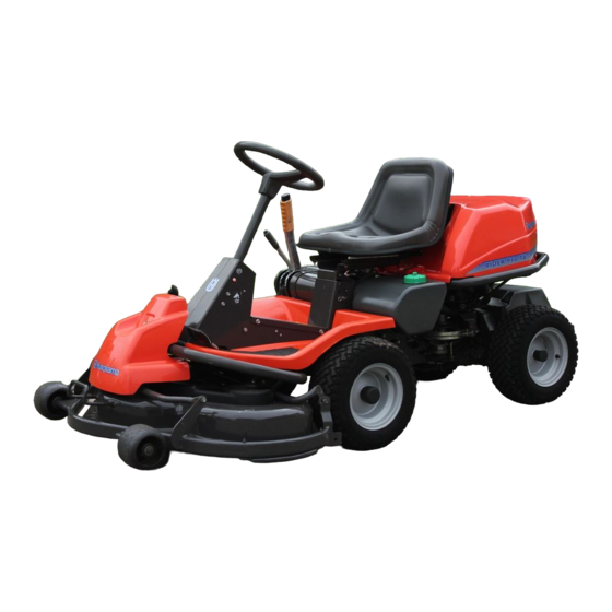
Page 12: Presentation
Presentation Congratulations on choosing an excellent quality product, Rider ProFlex. These instructions describe the Rider Pro 15. The Rider Pro 15 is equipped with a 15-horsepower four-stroke V-twin Kawasaki engine. Location of the controls 1. Ignition lock 2. Choke lever 3. -
Page 13: Throttle Control
Throttle control The throttle control regulates the engine speed, and thereby also the rotation speed of the blades. To increase or reduce the engine speed the control is moved forwards or backwards. Choke lever The choke lever is used for cold starting and to give the engine a richer fuel mixture. -
Page 14: Cutting Unit
Cutting unit Rider Pro 15 can be equipped with numerous attachments. The BioClip unit finely cuts the lawn by cutting the grass several times before returning the clippings to the lawn as fertiliser. Cutting unit with side ejection or rear ejection, i.e. -
Page 15: Lever For Adjustment Of Cutting Height
Lever for adjustment of the cutting height The cutting height can be adjusted to 9 different positions with the cutting height lever. Cutting unit with side/rear ejector, BioClip cutting unit, Parking brake The parking brake is applied as follows: 1. Push down the brake pedal (1). 2. -
Page 16: Driving
Before starting • Read the safety instructions and information on the location and function of the controls before starting (see pages 7–14). • Conduct daily maintenance before starting (see maintenance schedule on page 19-20). • Adjust the seat to the required position. Starting the engine 1. -
Page 17: Driving The Machine
5. When the engine starts release the ignition key immediately back to neutral position. IMPORTANT INFORMATION Do not run the starter for more than about 5 seconds at a time. If the engine does not start, wait about 15 seconds before trying again. -
Page 18: Cutting Tips
3. Push in the lock button on the lift lever and lower down the cutting unit. 4. Select the required cutting height (1–9) with the cutting height lever. Cutting tips • Localise and mark stones and other fixed objects to avoid collision. •... -
Page 19: Stopping The Engine
WARNING! Never drive the machine on ground at an angle of more than 15°. Mow slopes upwards and downwards, never across. Avoid sudden changes in direction. Stopping the engine Preferably allow the engine to idle for a minute to obtain normal working temperature before stopping it if it has been working hard. -
Page 20: Maintenance
The following is a list of the maintenance which should be conducted on the machine. For the items which are not described in these instructions go to an authorised service workshop. Maintenance Check for fuel and oil leakage Check the parking brake Check the engine oil level (when you refuel) Check the fuel pump air filter... - Page 21 Maintenance Lubricate throttle control Lubricate choke control Smörj styrkedja i ramtunnel. Lubricate steering chain inside frame tunnel Clean engine cooling air intake Clean the air filter pre-filter (oil-foam) Change engine oil Clean the air filter cartridge Check/adjust cutting height setting Check/adjust parking brake Inspect flame guard/spark arrestor (optional equipment)
-
Page 22: Removing Of The Machine Hoods
MAINTENANCE Removing of the machine hoods Engine hood Release the rubber strap securing the engine hood and raise the hood. Front hood Release the clip on the front hood and lift off the fender. Right-hand fender Dismantle the foot-plate (1), screws (2 and 3), and lift off the fender. -
Page 23: Checking And Adjusting The Steering Wires
Transmission cover Undo the two screws (one on each side) and lift off the transmission cover. Checking and adjustment of the steering wires The steering is controlled by means of wires. These can in time become slack, which implies that the adjustment of the steering becomes altered. -
Page 24: Adjusting The Brakes
Adjusting the brakes The parking brake (on the right) is adjusted as follows: 1. Remove the transmission cover. 2. Unhook the spring (A) from the screw (B). 3. Make sure the parking brake is released. 4. Adjust so there is 1 mm play between the outer cable and the adjuster screw when you pull the outer cable. -
Page 25: Replacement Of The Fuel Filter
Replacement of the fuel filter Replace the fuel filter every 100 running hours (once per season) or more frequently if it is clogged. Replace the filter as follows: 1. Release the rubber strap under the seat and raise the engine hood. 2. -
Page 26: Replacing The Air Filter
Replacing the air filter If the engine seems to lack power or does not run smoothly this may be because the air filter is clogged. It is therefore important to replace the air filter at regular intervals (see maintenance schedule on page 19-20 for correct service interval). -
Page 27: Checking The Transmission's Air Intake
Check the transmission’s air intake Check that the transmission’s air intake in not blocked. Check the engine’s cooling air intake Release the rubber strap under the seat and raise the engine hood. Check that the cooling intake is free from leaves, grass and dirt. -
Page 28: Check The Level Of The Battery Acid
Check the level of the battery acid Check that the level of the battery acid lies between the markings. Top up the cells with distilled water only . WARNING! Procedures on contact with acid External: Rinse well with plenty of water. Internal: Drink large quantities of water or milk. -
Page 29: Check The Safety System
Inspecting the safety system The Rider is equipped with a safety system that prevents starting or driving under the following conditions: The engine should only be possible to start when the cutting unit is in its raised position and the hydrostat pedals are in the neutral position. -
Page 30: Checking The Tyre Pressure
Checking the tyre pressure The tyre pressure should be 60 kPa (0.6 kp/cm all round. To improve driving the pressure on the rear tyres can be reduced to 40 kPa (0.4 kp/cm The maximum tyre pressure is 80 kPa (0,8 kp/cm IMPORTANT INFORMATION Different tyre pressures on the front tyres will result in the blades cutting the grass... -
Page 31: Fitting The Cutting Unit
Fitting the cutting unit 1. Position the Rider on a flat surface and apply the parking brake, see page 10. Check that the lever for adjusting the cutting height is at the lowest setting. Make sure the support wheels are fitted to the cutting unit (1). -
Page 32: Installing Bioclip 90
Installing BioClip 90 In order to install BioClip 90 the drive belt support wheel must first be removed. 1. Disengage the spring from the tensioning wheel. 3. Remove the locking pin (1) that is located next to the support wheel. 4. -
Page 33: Checking The Cutting Unit's Parallelism
Checking the cutting unit’s parallelism Check the parallelism of the cutting unit as follows: 1. Place the machine on a level surface. 2. Measure the distance between the ground and the front and rear edges of the cutting unit hood. The cutting unit should slope forwards slightly so that the rear edge is 2-4 mm higher than the front edge. -
Page 34: Removing The Cutting Unit
Removing the cutting unit WARNING! Wear protective glasses when removing the cutting unit. The spring which tensions up the belt can go off and cause personal injury. 1. Carry out steps 1-9 to put the cutting unit in the service position, see “Service position for cutting unit”... -
Page 35: Replacing The Cutting Unit's Belts
Replacing the cutting unit’s belts Belt replacement on the BioClip 103 There are two versions of BioClip 103. Version 1 has one toothed belt and version 2 has two. The toothed belts drive the blades and synchronise their rotation. The belts are located under a cover on top of the cutting unit. - Page 36 5. Version 2: Assembly: First fit the lower belt and then the upper belt. Ensure the blades are positioned as set out in the diagram, at 90 degrees to each other, otherwise the belts must be adjusted. When the blade bearings are loose the belts can be moved around to the next tooth.
-
Page 37: Service Position For The Cutting Unit
Service position for cutting unit The cutting head can be placed in the service position to provide easy access for cleaning, repairs and servicing. In the service position the cutting unit is raised and locked in the vertical position. Placing in service position 1. - Page 38 4. Fit the support wheels on either side of the rear of the cutting unit. WARNING! Wear protective glasses when dismantling the cutting unit. The spring which tensions up the belt can go off and cause personal injury. 5. Disengage the spring from the drive belt tensioning wheel.
- Page 39 8. Lift off the drive belt (1). Then pull out the pin (2). Take care not to get your hand trapped. 9. Pull the frame forwards and refit the pin. 10.Grasp the front edge of the cutting unit, pull out and raise into the service position.
-
Page 40: Checking The Blades
Checking the blades To achieve the best mowing results it is important that the blades are undamaged and well-sharpened. Check that the blades’ attachment screws are tight. IMPORTANT INFORMATION Replacing or sharpening the blades should be conducted by an authorised service workshop. -
Page 41: Replacing The Break-Pin (Bioclip)
Replacing the break-pin (BioClip) The blades are fitted with a break-pin to protect the BioClip unit and its drive when colliding with obstacles. A domed, spring friction washer is fitted to each blade bolt. The washer must always be replaced with a new washer if the blade bolt is loosened. -
Page 42: Lubrication
Lubrication chart 12/12 1/12 1/52 1/365 LUBRICATION Rider Pro 15 25h 100h 200h 500h (1/52) English –... -
Page 43: General Lubrication
General Remove the ignition key to prevent accidental movement during lubrication. If lubricating with an oil can, fill the can with engine oil. If lubricating with grease, use grease 503 98 96-01 or a similar chassis grease or bearing grease with good corrosion resistance, unless otherwise specified. - Page 44 2. Pedal mechanism in frame tunnel Lubricate the pedal mechanism in the frame tunnel. Remove the cover from the frame tunnel by undoing the screws, two on each side Pump the pedals and lubricate the moving parts using an oil can Lubricate the wires connected to the brake and drive pedals using an oil can Lubricate as described under “Chains in frame...
- Page 45 LUBRICATION 5. Driver’s seat Tip up the seat. Lubricate the linkage of the scissor springs using an oil can; there are 8 lubrication points. Lubricate the seat leg length adjustment mechanism using an oil can. Lubricate the leg length adjustment rails using an oil can.
-
Page 46: Engine Oil
8. Engine oil Check the engine oil level when the Rider is on level ground. Release the rubber strap under the seat and raise the engine hood. Take out the dipstick, wipe it clean and push it in again. Do not screw in the dipstick. Take out the dipstick again and read the oil level. -
Page 47: Gear Lever
9. Gear lever Remove the transmission cover by undoing the two screws. Lubricate the joints and bearings on the left side using an oil can. Push the rubber protector out of the way and lubricate the hydrostatic wire using an oil can. Press the pedal a few times and lubricate again. - Page 48 12. Transmission The oil and filter should be replaced by an authorised service workshop as described in the workshop manual. 13. Replacing the oil filter WARNING! The engine oil may be very hot if it is drained immediately after stopping the engine. Let the engine cool down for a while first.
-
Page 49: Trouble Shooting Schedule
TROUBLE SHOOTING SCHEDULE Problem Engine will not start. Starter does not pull round engine. Engine does not run smoothly. Engine seems to have no power. Engine overheats. Battery does not charge. Machine vibrates. Uneven mowing. – English Procedure • Fuel tank empty. •... -
Page 50: Storage
Winter storage At the end of the season the machine should immediately be put in order for storage, also if it is going to stand idle for more than 30 days. Fuel which is left to stand for long periods (30 days or more) can leave tacky deposits which can block the carburettor and interfere with the engine. -
Page 51: Wiring Diagram
1. Microswitch, hydrostatic transmission 2. Microswitch, cutting unit 3. Microswitch, seat 4. Ignition lock 5. Counter 6. Start relay 7. Engine 8. Fuse 15 A – English WIRING DIAGRAM Explanation of colour abbreviations in wiring diagram. R = Red B = Blue W = White BL = Black Y = Yellow... -
Page 52: Technical Data
When the service life of this product has been served and it is no longer used it should be returned to the dealer or to an applicable station for recycling. TECHNICAL DATA Rider Pro 15 Rider Pro 15 2 145 mm... - Page 53 We, Husqvarna AB, S-561 82 Huskvarna, Sweden, tel. +46 36-146500, declare under sole responsibility that the rider mowers Husqvarna Rider Pro from 1998’s serial numbers and onwards (the year is clearly stated in plain text on the type plate with subsequent serial number), is in conformity with the following standards or other normative documents following the provisions in the COUNCIL’S DIRECTIVES:...
-
Page 54: Servicejournal
Work done Pre-delivery service 1. Top up battery with acid and recharge for four hours. 2. Fit steering wheel, seat and any optional equipment. 3. Fit cutting unit. 4. Adjust cutting unit: Adjust lift springs (effective weight of cutting unit should be 12–15 kg, or set to maximum lift if brush is to be fitted). - Page 55 Work done 25 hour service 1. Clean the air filter pre-filter (oil-foam element). (more regularly in dusty conditions) 2. Clean the engine cooling air intake and transmission air intake. 3. Clean the fuel pump air filter. (in dusty conditions). – English SERVICEJOURNAL Date, mileage, stamp, sign...
- Page 56 SERVICEJOURNAL Work done Date, mileage, stamp, sign 50 hour service 1. Clean / replace the air filter pre-filter (oil-foam element). (more regularly in dusty conditions) 2. Clean the engine cooling air intake and transmission air intake. 3. Clean the paper air filter. 4.
- Page 57 Work done 100/200 hour service 1. Change the engine oil. Change the oil filter every 200 hours. 2. Clean / replace the air filter pre-filter (oil-foam element). 3. Clean the paper air filter. Replace every 200 hours. (more regularly in dusty conditions) 4.
- Page 58 SERVICEJOURNAL Work done Date, mileage, stamp, sign 300 hour service 1. Change engine oil. 2. Replace the air filter (oil-foam element). 3. Replace air filter ( paper air filter). Clean the fuel pump air filter. 5. Check/adjust cutting height setting. 6.
- Page 59 Work done At least once a season 1. Change engine oil (100 hours). 2. Clean / replace the air filter pre-filter (oil-foam element) (25 hours). (more regularly in dusty conditions) 3. Clean / replace the paper air filter (100 hours). (more regularly in dusty conditions).
- Page 60 SERVICEJOURNAL Date, mileage, stamp, sign Work done English –...
- Page 61 SERVICEJOURNAL Date, mileage, stamp, sign Work done – English ´*3-Q¶5w¨...
- Page 62 English –...
- Page 63 ´*3-Q¶5w¨ 2001W02...