Fujitsu Eternus DX60 User Manual
Disk storage system
Hide thumbs
Also See for Eternus DX60:
- User manual (242 pages) ,
- Operation manual (119 pages) ,
- Product introduction (19 pages)
Table of Contents
Quick Links
Table of Contents

Related Manuals for Fujitsu Eternus DX60


Summary of Contents for Fujitsu Eternus DX60
-
Page 3: Using This Manual
Keep these manuals in a safe place for future reference. Fujitsu pays careful attention to the safe use of its products to prevent user injury and/or material damage. To use the ETERNUS DX60/DX80/DX90 properly, please follow the instructions in this manual. - Page 4 Do not use the ETERNUS DX60/DX80/DX90 for High Safety Required Use without securing the sufficient safety level required. If you wish to use the ETERNUS DX60/DX80/DX90 for High Safety Required Use, please consult with our sales representative before such use.
- Page 5 Preface P3AM-3042-06ENZ0 ETERNUS DX60/DX80/DX90 Disk storage system User Guide Copyright 2010 FUJITSU LIMITED...
-
Page 6: About This Manual
This chapter describes the components of the ETERNUS DX60/DX80/DX90. • Chapter 3 Standard Operations This chapter describes how to turn the ETERNUS DX60/DX80/DX90 on and off, and how to attach and remove the front cover or flange cover. • Chapter 4 Flow from Installation to Operation This chapter describes the flow of work from installation to the start of ETERNUS DX60/ DX80/DX90 operation. - Page 7 ETERNUS DX60/DX80/DX90 is not used properly. This symbol indicates the possibility of minor or moderate personal CAUTION injury, as well as damage to the ETERNUS DX60/DX80/DX90 and/or to other users and their property, if the ETERNUS DX60/DX80/DX90 is not used properly.
-
Page 8: Additional Information
ETERNUS DX60/DX80/DX90: - Make sure to disconnect the power when cleaning. - Be careful that no liquid seeps into the ETERNUS DX60/DX80/DX90 when using cleaners, etc. - Do not use alcohol or other solvents to clean the ETERNUS DX60/DX80/DX90. - Page 9 Latest Information The information in this document is subject to change without notice for functionality expansion of ETERNUS DX60/DX80/DX90 and improvement. The latest version of this document and the latest information about the ETERNUS DX60/DX80/DX90 is released in the following web-site.
- Page 10 Download the necessary manuals for the customer operating environment (for server OS, Fibre Channel card type, etc.) from the specified web-site. For the URL of the download web-site, refer to the Documentation CD provided with the ETERNUS DX60/DX80/DX90. P3AM-3042-06ENZ0 ETERNUS DX60/DX80/DX90 Disk storage system User Guide...
- Page 11 Labels Warning labels and manufacturer's labels are found in various places of the ETERNUS DX60/ DX80/DX90, as shown in the example below. Do not remove these labels. Controller Enclosure Manufacturer’s label The label with the model, serial #, etc. is located here.
-
Page 12: Drive Enclosure
Labels Drive Enclosure AC Outlet Box (1U) Manufacturer’s label The label with the model, serial #, etc. is located here. P3AM-3042-06ENZ0 ETERNUS DX60/DX80/DX90 Disk storage system User Guide Copyright 2010 FUJITSU LIMITED... - Page 13 Labels AC Outlet Box (2U) Manufacturer’s label The label with the model, serial #, etc. is located here. P3AM-3042-06ENZ0 ETERNUS DX60/DX80/DX90 Disk storage system User Guide Copyright 2010 FUJITSU LIMITED...
-
Page 14: Table Of Contents
2.5.1 AC Outlet Box (1U) ........................71 2.5.2 AC Outlet Box (2U) ........................71 Chapter 3 Standard Operations..............72 Power ON Control .................... 72 Power OFF Control ..................74 P3AM-3042-06ENZ0 ETERNUS DX60/DX80/DX90 Disk storage system User Guide Copyright 2010 FUJITSU LIMITED... - Page 15 Advanced Copy Settings ......................169 Monitoring Setup .................... 169 7.4.1 Event Notification Setup ......................169 7.4.2 E-mail Notification Setup ......................172 7.4.3 ServerView (SNMP Trap Notification) Setup ................173 P3AM-3042-06ENZ0 ETERNUS DX60/DX80/DX90 Disk storage system User Guide Copyright 2010 FUJITSU LIMITED...
- Page 16 Drive Enclosure Rack Installation Procedure ................192 8.2.4 Additional Drive Enclosure Installation ..................198 Chapter 9 Operation and Maintenance ..........201 Checking the ETERNUS DX60/DX80/DX90 Status ........201 Backing up Data ..................... 201 Maintenance Service ..................202 9.3.1 Maintenance Support Period ....................202 Post Start-of-Operation Changes to the Configuration ........
- Page 17 Contents Appendix B Events detected by ServerView ..........229 Appendix C About Using of Open Sources ..........230 Index .......................233 P3AM-3042-06ENZ0 ETERNUS DX60/DX80/DX90 Disk storage system User Guide Copyright 2010 FUJITSU LIMITED...
- Page 18 Figure 2.14 Rear view of 2.5" type controller enclosure (single controller model)........59 Figure 2.15 Rear view of 2.5" type controller enclosure (dual controller model) .......... 59 Figure 2.16 ETERNUS DX60/DX80 Fibre Channel model controller ............60 Figure 2.17 ETERNUS DX90 Fibre Channel model controller ..............61 Figure 2.18 Power supply unit (2.5"...
- Page 19 Figure 7.33 [Setup Event Notification] screen (Informational Level)............171 Figure 7.34 [Setup E-Mail Notification] screen (Notification E-Mail) ............172 Figure 7.35 [Setup E-Mail Notification] screen (Mail Server Settings)............173 Figure 7.36 Send Test E-mail ........................173 P3AM-3042-06ENZ0 ETERNUS DX60/DX80/DX90 Disk storage system User Guide Copyright 2010 FUJITSU LIMITED...
- Page 20 [Add Drive Enclosure] - Workflow Sequence screen 2............200 Figure 9.1 ETERNUS Multipath Manager Window................... 211 Figure 9.2 Trouble record (1/2)......................... 213 Figure 9.3 Trouble record (2/2)......................... 214 P3AM-3042-06ENZ0 ETERNUS DX60/DX80/DX90 Disk storage system User Guide Copyright 2010 FUJITSU LIMITED...
- Page 21 Table A.22 Expansion expander specifications ..................228 Table A.23 Expansion expander specifications ..................228 Table A.24 Extension cable kit specifications .................... 228 Table B.1 ServerView event list ....................... 229 P3AM-3042-06ENZ0 ETERNUS DX60/DX80/DX90 Disk storage system User Guide Copyright 2010 FUJITSU LIMITED...
-
Page 22: Overview
ETERNUS DX60/DX80/DX90. Up to 24 disks can be installed in the ETERNUS DX60 and up to 120 disks in the ETER- NUS DX80/DX90. •... - Page 23 Both 3.5" SAS disks (300GB/450GB/600GB; 15,000rpm), and 2.5" SAS disks (146GB/ 300GB; 10,000rpm) are available. For data backup and archival purposes the ETERNUS DX60/DX80/DX90 is able to use large (*1) capacity, highly cost effective 3.5" Nearline SAS disks (750GB/1TB/2TB; 7,200rpm).
- Page 24 • Redundant copy ensures disk redundancy The ETERNUS DX60/DX80/DX90 diagnostic routines test the disks in order to predict failures before they happen. When a disk requires preventive maintenance, a hot spare is automatically switched in to replace it, providing continued data redundancy and stable operation.
- Page 25 The SCU is charged so quickly that write performance is recovered right after power recovery. E-mail notification If an error occurs in the ETERNUS DX60/DX80/DX90, the details can be sent to a specified e- mail address. Strengthening security against information leaks •...
-
Page 26: Configuration
Chapter 1 Overview > 1.2 Configuration Configuration This chapter describes items to be noted before configuring the ETERNUS DX60/DX80/DX90 systems. 1.2.1 RAID Level This section describes the supported RAID level and usage (RAID level selection criteria), and RAID group configuration. - Page 27 RAID1 stores the same data on two duplicated disks at the same time. If one disk fails, other disk continues operation. Data writing request HDD0 HDD1 Figure 1.2 RAID1 concept P3AM-3042-06ENZ0 ETERNUS DX60/DX80/DX90 Disk storage system User Guide Copyright 2010 FUJITSU LIMITED...
- Page 28 Parity E, F, G, H Parity for data I to L: Parity I, J, K, L Parity for data M to P Parity M, N, O, P Figure 1.4 RAID5 concept P3AM-3042-06ENZ0 ETERNUS DX60/DX80/DX90 Disk storage system User Guide Copyright 2010 FUJITSU LIMITED...
- Page 29 G, H I, J K, L O, P M, N HDD0 HDD1 HDD2 HDD3 HDD4 HDD5 RAID5 RAID5 Striping (RAID0) Striping with distributed parity (RAID5) Figure 1.5 RAID5+0 concept P3AM-3042-06ENZ0 ETERNUS DX60/DX80/DX90 Disk storage system User Guide Copyright 2010 FUJITSU LIMITED...
- Page 30 750GB Nearline SAS disk 702,976MB 1TB Nearline SAS disk 937,728MB 2TB Nearline SAS disk 1,866,240MB The above User Capacities are based on a 1MB = 1,024 Byte metric. P3AM-3042-06ENZ0 ETERNUS DX60/DX80/DX90 Disk storage system User Guide Copyright 2010 FUJITSU LIMITED...
- Page 31 For read only file servers and backup servers, RAID5, RAID5+0, or RAID6 can also be used. However, if the disk fails, note that data restoration from parities and rebuilding process may result in a loss in performance. P3AM-3042-06ENZ0 ETERNUS DX60/DX80/DX90 Disk storage system User Guide Copyright 2010 FUJITSU LIMITED...
-
Page 32: Raid Groups And Volumes
1.2.2 RAID Groups and Volumes RAID group In an ETERNUS DX60/DX80/DX90 Disk storage system, you can set up the RAID groups to all use the same RAID level or a mixture of different RAID levels. RAID Group 1 RAID Group 2 Figure 1.7... -
Page 33: System Disks
Slot0 and Slot1 in the controller enclosure. Do Not WARNING • Do not remove system disks. Doing so will render the ETERNUS DX60/DX80/DX90 unusable. System disks cannot be registered as hot spares. IMPORTANT P3AM-3042-06ENZ0 ETERNUS DX60/DX80/DX90 Disk storage system User Guide Copyright 2010 FUJITSU LIMITED... -
Page 34: Hot Spare
Assign "Dedicated Hot spares" to RAID groups that contain important data, in order to preferentially improve their access to hot spares. For details about Global Hot spare and Dedicated Hot spare, refer to the "ETERNUS DX60/ DX80/DX90 Web GUI User Guide". -
Page 35: Disks
Fibre Channel interface Fibre Channel supports two connection topologies, Arbitrated Loop and Fabric. Maximum transfer speed is 4Gbit/s for the ETERNUS DX60, 8Gbit/s or 4Gbit/s for the ETERNUS DX80, and 8Gbit/s for the ETERNUS DX90. Fibre Channel is commonly used for database servers. A fabric connection via an FC switch will allow a large number of high-performance hosts to connect to a single port if required. -
Page 36: Functions
Chapter 1 Overview > 1.3 Functions Functions This section describes the main ETERNUS DX60/DX80/DX90 functions. 1.3.1 Rebuild/Copyback When a disk fails and the RAID group redundancy has been broken, Rebuild/Copyback restores the disk status back to normal status as a background process. - Page 37 Approx. 20 minutes/100GB The time required to copyback a 100GB volume of the indicated RAID level, number and type of disks when there is no concurrent server I/O. P3AM-3042-06ENZ0 ETERNUS DX60/DX80/DX90 Disk storage system User Guide Copyright 2010 FUJITSU LIMITED...
-
Page 38: Redundant Copy
Hot Spare Sign of failure RAID5 (Redundancy) Disconnects the maintenance target disk and installs the hot spare. RAID5 (Redundancy) Disconnected Figure 1.11 Redundant Copy Function P3AM-3042-06ENZ0 ETERNUS DX60/DX80/DX90 Disk storage system User Guide Copyright 2010 FUJITSU LIMITED... -
Page 39: Advanced Copy
1.3.3 Advanced Copy The Advanced Copy functions allows the ETERNUS DX60/DX80/DX90 to carry out high-speed data copying operations on its own, with no need to draw on server resources. The Advanced Copy functions of the ETERNUS DX60/DX80/DX90 have the following uses: •... - Page 40 REC is used to copy data among multiple devices using the EC copy method. REC is suitable for the following usages. Replicating system test datasets Duplicating databases on multiple devices Backing up data to remote devices P3AM-3042-06ENZ0 ETERNUS DX60/DX80/DX90 Disk storage system User Guide Copyright 2010 FUJITSU LIMITED...
- Page 41 SnapOPC+, SnapOPC+ QuickOPC, copy type QuickOPC OPC, EC Table 1.10 Maximum number of copy sessions License None Registered ETERNUS DX60/DX80/DX90 DX60 DX80/DX90 Maximum number 1024 of copy sessions P3AM-3042-06ENZ0 ETERNUS DX60/DX80/DX90 Disk storage system User Guide Copyright 2010 FUJITSU LIMITED...
-
Page 42: Raid Migration
Migrate to another RAID group and add the capacity LUN0 600GB LUN1 300GB LUN2 450GB Define LUN2 additionally in the surplus space Figure 1.13 Example for use RAID Migration 1 P3AM-3042-06ENZ0 ETERNUS DX60/DX80/DX90 Disk storage system User Guide Copyright 2010 FUJITSU LIMITED... -
Page 43: Figure 1.14 Example For Use Raid Migration 2
Migrate to another RAID group 300GB 300GB 300GB 300GB 300GB 300GB LUN0 900GB 300GB 300GB 300GB 300GB 300GB 300GB LUN0 900GB Figure 1.14 Example for use RAID Migration 2 P3AM-3042-06ENZ0 ETERNUS DX60/DX80/DX90 Disk storage system User Guide Copyright 2010 FUJITSU LIMITED... -
Page 44: Logical Device Expansion
300GB 300GB 300GB 300GB LUN0 600GB LUN1 300GB RAID5(4+1) 300GB 300GB 300GB 300GB 300GB LUN0 600GB LUN1 300GB LUN2 300GB Figure 1.15 Example for use Logical Device Expansion P3AM-3042-06ENZ0 ETERNUS DX60/DX80/DX90 Disk storage system User Guide Copyright 2010 FUJITSU LIMITED... -
Page 45: Lun Concatenation
Unused area 600GB LUN2 300GB RAID5(3+1) RAID5(3+1) 300GB 300GB 300GB 300GB 300GB 300GB 300GB 300GB LUN1 300GB LUN0 600GB LUN2 900GB Figure 1.16 Example for use LUN Concatenation P3AM-3042-06ENZ0 ETERNUS DX60/DX80/DX90 Disk storage system User Guide Copyright 2010 FUJITSU LIMITED... -
Page 46: Security Functions
1.3.7 Security Functions The ETERNUS DX60/DX80/DX90 possesses functions that allow numbers of volumes, that can be recognized by a server, to be expanded or restricted by adjusting how the logical units (LUN) seen by the host correspond to the volumes within the storage system. -
Page 47: Figure 1.18 Host Affinity Function
Apply Affinity Group #01 for the access from LUN#0 WWN#C (=Server C) LUN#127 Figure 1.18 Host Affinity function When multiple servers access the device using the same port, this assigns Affinity Group for each server. P3AM-3042-06ENZ0 ETERNUS DX60/DX80/DX90 Disk storage system User Guide Copyright 2010 FUJITSU LIMITED... -
Page 48: Eco-Mode
Twenty-four 750GB Nearline SAS disks (0:00 to 12:00) (12:00 to 24:00) RAID5 ETERNUS Activate the whole DX60/DX80/DX90 system between 0:00 to 5:00 Figure 1.20 Setting example for Eco-mode schedule P3AM-3042-06ENZ0 ETERNUS DX60/DX80/DX90 Disk storage system User Guide Copyright 2010 FUJITSU LIMITED... -
Page 49: Components
Power switch Used to turn the device ON and OFF. Figure 2.1 Front view of 3.5" type controller enclosure (with front cover) P3AM-3042-06ENZ0 ETERNUS DX60/DX80/DX90 Disk storage system User Guide Copyright 2010 FUJITSU LIMITED... - Page 50 Blinks orange ( ) according to the VDS (Microsoft Virtual Disk Service) commands. Disk Up to 12 disks can be installed in the ETERNUS DX60/DX80/DX90. AUTO POWER Switch Enables the AC Auto-Link Mode (This function automatically turns on the linked device once AC power is supplied).
-
Page 51: Rear View
SCU. cache memory, and SCU. Power Supply Unit Power Supply (PSU#0) Unit (PSU#1) Figure 2.5 Rear view of 3.5" type controller enclosure (dual controller model) P3AM-3042-06ENZ0 ETERNUS DX60/DX80/DX90 Disk storage system User Guide Copyright 2010 FUJITSU LIMITED... - Page 52 2.1 3.5" Type Controller Enclosure Controller (CM) • ETERNUS DX60/DX80 Fibre Channel model Figure 2.6 shows the ETERNUS DX60/DX80 Fibre Channel model controller. SCU STATUS LED Glows green ( ) when SCU is normal. Blinks green ( ) when being charged (for about one minute after the device power is turned on).
- Page 53 ) when link has been established. SAS (OUT) port Connector for a miniSAS cable Used to connect the Controller Enclosure to a Drive Enclosure. Figure 2.7 ETERNUS DX90 Fibre Channel model controller P3AM-3042-06ENZ0 ETERNUS DX60/DX80/DX90 Disk storage system User Guide Copyright 2010 FUJITSU LIMITED...
- Page 54 Chapter 2 Components > 2.1 3.5" Type Controller Enclosure • ETERNUS DX60/DX80 iSCSI model Figure 2.8 shows the ETERNUS DX60/DX80 iSCSI model controller. SCU STATUS LED Glows green ( ) when SCU is normal. Blinks green ( ) when being charged (for about one minute after the device power is turned on).
- Page 55 Chapter 2 Components > 2.1 3.5" Type Controller Enclosure • ETERNUS DX60/DX80 SAS model Figure 2.9 shows the ETERNUS DX60/DX80 SAS model controller. SCU STATUS LED Glows green ( ) when SCU is normal. Blinks green ( ) when being charged (for about one minute after the device power is turned on).
-
Page 56: Figure 2.10 Power Supply Unit (3.5" Type Controller Enclosure)
Power cords should not be reconnected immediately after being disconnected. Always wait for the power supply unit's STATUS LED to completely turn off (about 10 seconds) before reconnecting a disconnected power cord. P3AM-3042-06ENZ0 ETERNUS DX60/DX80/DX90 Disk storage system User Guide Copyright 2010 FUJITSU LIMITED... -
Page 57: Type Controller Enclosure
) when a disk has failed. Blinks orange ( ) according to the VDS (Microsoft Virtual Disk Service) commands. Disk Up to 24 disks can be installed in the ETERNUS DX60/DX80/DX90. Flange cover POWER LED Glows green ( ) when the power is turned on. -
Page 58: Figure 2.12 Front View Of 2.5" Type Controller Enclosure (Without Flange Cover)
RAID groups, volumes, and hot spares are factory set. Disks which contain RAID groups or volumes, or disks which are hot spares should not be moved to another slot. P3AM-3042-06ENZ0 ETERNUS DX60/DX80/DX90 Disk storage system User Guide Copyright 2010 FUJITSU LIMITED... -
Page 59: Figure 2.14 Rear View Of 2.5" Type Controller Enclosure (Single Controller Model)
SCU. cache memory, and SCU. Power Supply Unit Power Supply (PSU#0) Unit (PSU#1) Figure 2.15 Rear view of 2.5" type controller enclosure (dual controller model) P3AM-3042-06ENZ0 ETERNUS DX60/DX80/DX90 Disk storage system User Guide Copyright 2010 FUJITSU LIMITED... -
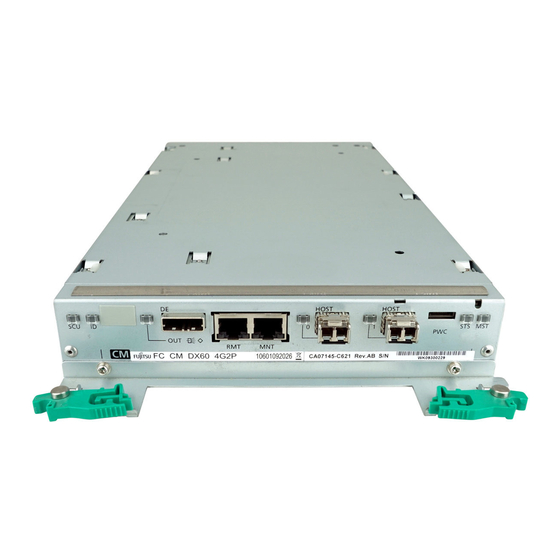
Page 60: Figure 2.16 Eternus Dx60/Dx80 Fibre Channel Model Controller
2.2 2.5" Type Controller Enclosure Controller (CM) • ETERNUS DX60/DX80 Fibre Channel type Figure 2.16 shows the ETERNUS DX60/DX80 Fibre Channel model controller. SCU STATUS LED Glows green ( ) when SCU is normal. Blinks green ( ) when being charged (for about one minute after the device power is turned on). -
Page 61: Figure 2.17 Eternus Dx90 Fibre Channel Model Controller
There is no limit to the post-failure data retention time. • SCU failure will disable the cache function, leading to degraded performance. P3AM-3042-06ENZ0 ETERNUS DX60/DX80/DX90 Disk storage system User Guide Copyright 2010 FUJITSU LIMITED... -
Page 62: Figure 2.18 Power Supply Unit (2.5" Type Controller Enclosure)
Power cords should not be reconnected immediately after being disconnected. Always wait for the power supply unit's STATUS LED to completely turn off (about 10 seconds) before reconnecting a disconnected power cord. P3AM-3042-06ENZ0 ETERNUS DX60/DX80/DX90 Disk storage system User Guide Copyright 2010 FUJITSU LIMITED... -
Page 63: Type Drive Enclosure
IDENTIFY LED Blinks blue or turns off as ordered via GUI to identify the enclosure installation locations. Figure 2.19 Front view of 3.5" type drive enclosure (with front cover) P3AM-3042-06ENZ0 ETERNUS DX60/DX80/DX90 Disk storage system User Guide Copyright 2010 FUJITSU LIMITED... -
Page 64: Figure 2.20 Front View Of 3.5" Type Drive Enclosure (Without Front Cover)
Slot#8 Slot#9 Slot#10 Slot#11 Slot#4 Slot#5 Slot#6 Slot#7 Slot#0 Slot#1 Slot#2 Slot#3 Figure 2.21 Disk slot numbers of 3.5" type drive enclosure P3AM-3042-06ENZ0 ETERNUS DX60/DX80/DX90 Disk storage system User Guide Copyright 2010 FUJITSU LIMITED... -
Page 65: Figure 2.22 Rear View Of 3.5" Type Drive Enclosure (Single Expander Model)
Power Supply Unit Power Supply (PSU#0) Unit (PSU#1) DE_No. label Indicates the drive enclosure No. Figure 2.23 Rear view of 3.5" type drive enclosure (dual expander model) P3AM-3042-06ENZ0 ETERNUS DX60/DX80/DX90 Disk storage system User Guide Copyright 2010 FUJITSU LIMITED... -
Page 66: Figure 2.24 Expander (3.5" Type Drive Enclosure)
DC power is turned on. Glows orange ( ) to indicate a fault has been detected in a fan or power supply. Figure 2.25 Power supply unit (3.5" type drive enclosure) P3AM-3042-06ENZ0 ETERNUS DX60/DX80/DX90 Disk storage system User Guide Copyright 2010 FUJITSU LIMITED... -
Page 67: Front View
) when a disk has failed. Blinks orange ( ) according to the VDS (Microsoft Virtual Disk Service) commands. Disk DE_No. label Up to 24 can be installed in the ETERNUS DX60/DX80/DX90. Indicates the drive enclosure No. Flange cover POWER LED... -
Page 68: Figure 2.27 Front View Of 2.5" Type Drive Enclosure (Without Flange Cover)
RAID groups, volumes, and hot spares are factory set. Disks which contain RAID groups or volumes, or disks which are hot spares should not be moved to another slot. P3AM-3042-06ENZ0 ETERNUS DX60/DX80/DX90 Disk storage system User Guide Copyright 2010 FUJITSU LIMITED... -
Page 69: Figure 2.29 Rear View Of 2.5" Type Drive Enclosure (Single Expander Model)
Power Supply Unit Power Supply (PSU#0) Unit (PSU#1) DE_No. label Indicates the drive enclosure No. Figure 2.30 Rear view of 2.5" type drive enclosure (dual expander model) P3AM-3042-06ENZ0 ETERNUS DX60/DX80/DX90 Disk storage system User Guide Copyright 2010 FUJITSU LIMITED... -
Page 70: Figure 2.31 Expander (2.5" Type Drive Enclosure)
DC power is turned on. Glows orange ( ) to indicate a fault has been detected in a fan or power supply. Figure 2.32 Power supply unit (2.5" type drive enclosure) P3AM-3042-06ENZ0 ETERNUS DX60/DX80/DX90 Disk storage system User Guide Copyright 2010 FUJITSU LIMITED... -
Page 71: Ac Outlet Box (2U)
Main line switch Inlet Power cords (AC Input cable are connected here. Outlet (OUTPUT) Power cords (AC output cable) are connected here. Figure 2.34 AC outlet box (2U) P3AM-3042-06ENZ0 ETERNUS DX60/DX80/DX90 Disk storage system User Guide Copyright 2010 FUJITSU LIMITED... -
Page 72: Standard Operations
When the AUTO POWER switch of the controller enclosure is turned to "ON", supplying power to the ETERNUS DX60/DX80/DX90 will cause the ETERNUS DX60/DX80/DX90 to turn on automatically in cases such as when the power cord is connected or the power is recovered after power failure. - Page 73 Check that all enclosure’s POWER LED and READY LED are lit up. LED for drive enclosure Drive enclosure Drive enclosure Controller enclosure LED for controller enclosure End of procedure P3AM-3042-06ENZ0 ETERNUS DX60/DX80/DX90 Disk storage system User Guide Copyright 2010 FUJITSU LIMITED...
-
Page 74: Power Off Control
• Do not turn off the power of the device or network devices that connect the ETERNUS DX60/DX80/DX90 and server while the server is operating. Turning the power off may result in the loss of data or prevent data from being saved. -
Page 75: Attaching And Removing The Front Cover
Fit the front cover in the left end slot of the controller enclosure to attach. Be careful so that the part of the front cover to be fit in the slot does IMPORTANT not touch the power switch ( Slot P3AM-3042-06ENZ0 ETERNUS DX60/DX80/DX90 Disk storage system User Guide Copyright 2010 FUJITSU LIMITED... - Page 76 Holding the tab on the front cover, attach the right side of the cover to the enclosure. CAUTION • When removing the front cover, support its left side with your left hand, to prevent it from coming loose and falling. End of procedure P3AM-3042-06ENZ0 ETERNUS DX60/DX80/DX90 Disk storage system User Guide Copyright 2010 FUJITSU LIMITED...
- Page 77 When attaching the right side of the front cover, support its left side with your left hand, to prevent it from coming loose and falling. End of procedure P3AM-3042-06ENZ0 ETERNUS DX60/DX80/DX90 Disk storage system User Guide Copyright 2010 FUJITSU LIMITED...
-
Page 78: Attaching And Removing The Flange Cover
Slide the tab inside the top of the flange cover over the top-left corner of the controller enclosure. When fitting the flange cover, be careful not to touch the power IMPORTANT switch ( Flange cover P3AM-3042-06ENZ0 ETERNUS DX60/DX80/DX90 Disk storage system User Guide Copyright 2010 FUJITSU LIMITED... -
Page 79: Turning The Auto Power Switch On/Off
This section explains how to enable the AC automatic linkage mode by turning the AUTO POWER switch of the controller enclosure to "ON". When AC automatic linkage mode is enabled, the ETERNUS DX60/DX80/DX90 is automatically turned on when the power supply recovers after a power failure. - Page 80 "3.3 Attaching and Removing the Front Cover" (page 75). For details on how to attach the flange cover, refer to "3.4 Attaching and Removing the Flange Cover" (page 78). End of procedure P3AM-3042-06ENZ0 ETERNUS DX60/DX80/DX90 Disk storage system User Guide Copyright 2010 FUJITSU LIMITED...
-
Page 81: Wearing The Wrist Strap
Remove the protective film from part A, and attach it to the metal frame of the rack. Wrap around your wrist Connect to the metal frame of the rack Figure 3.1 Wrist strap P3AM-3042-06ENZ0 ETERNUS DX60/DX80/DX90 Disk storage system User Guide Copyright 2010 FUJITSU LIMITED... -
Page 82: Chapter 4 Flow From Installation To Operation
Chapter 4 Flow from Installation to Operation This chapter explains the flow of work from installation to the start of ETERNUS DX60/DX80/ DX90 operation. Preparation Package Contents Check Refer to "ETERNUS DX60/DX80/DX90 Disk storage system Package Contents" and check that there are no missing parts. - Page 83 Power cords Refer "Chapter 6 Cable Connection" (page 106) Startup Connect the PC to the ETERNUS DX60/DX80/DX90 with a LAN cable (for operation man- agement), and turn on the ETERNUS DX60/DX80/DX90. Refer "7.1 Setup Preparation" (page 136) "7.2 Basic Setup" (page 139)
- Page 84 Configure Affinity Group • Define LUN Mapping Refer "7.2.2 Configuration Wizard" (page 149) Assigning Hot Spares To add hot spares, register them. Refer "7.2.3 Hot Spare Registration" (page 160) P3AM-3042-06ENZ0 ETERNUS DX60/DX80/DX90 Disk storage system User Guide Copyright 2010 FUJITSU LIMITED...
- Page 85 Notification of ETERNUS DX60/DX80/DX90 problems as they occur is possible if the event notification method and level have been set. • If e-mail notification of ETERNUS DX60/DX80/DX90 errors is to be used, set a recipient e-mail address. • If the ETERNUS DX60/DX80/DX90 is connected to a PRIMERGY server and the "ServerView"...
-
Page 86: Chapter 5 Installation
The inside of the ETERNUS DX60/DX80/DX90 is cooled down by taking air through the front side and blowing it out the back. Place other devices so that the front of the ETERNUS DX60/ DX80/DX90 is not exposed to their exhaust air. -
Page 87: Check The Number Of Wall Outlets
Check the required type and number of the wall outlets. Type of wall outlet connectors All ETERNUS DX60/DX80/DX90 device models include US spec. AC200-240V cables (with plug) as standard. In addition, power cords must comply with the particular safety standards of the country of use. In some cases, a power cord will need to be purchased locally to satisfy the relevant power safety requirements. -
Page 88: Rack Installation
No. of power outlets Rack Installation This section describes the procedure for installing the ETERNUS DX60/DX80/DX90 in a rack. Make sure to check "ETERNUS DX60/DX80/DX90 Disk storage system Safety Precautions" before installation. Also refer to the manual provided with racks. - Page 89 5.2 Rack Installation Installation conditions for other rack brands When installing the ETERNUS DX60/DX80/DX90 in other 19-inch rack brands, make sure that the following conditions are met. Note that there is no guarantee that operations will perform properly when other rack brands are used to install the ETERNUS DX60/DX80/DX90.
- Page 90 AC outlet box (2U) (*2) One 2U size AC outlet box is installed in this example. Alternatively, three 1U size AC outlet boxes need to be installed instead. P3AM-3042-06ENZ0 ETERNUS DX60/DX80/DX90 Disk storage system User Guide Copyright 2010 FUJITSU LIMITED...
-
Page 91: Installing Controller Enclosure
For the ETERNUS DX80/DX90 (2.5" disk model), 3.5" type and 2.5" type IMPORTANT enclosures can be installed together. • ETERNUS DX60/DX80/DX90 components should be installed in a rack in the following order (from the bottom upwards): (1) AC outlet box(es) (2) Controller enclosure (3) Drive enclosure(s) 5.2.1... - Page 92 Screw holders M5 screws M5 screws Bracket L (Rear rack pillars) Screw holders Screw holders M5 screws (Front rack pillars) M5 screws Bracket R Screw holders P3AM-3042-06ENZ0 ETERNUS DX60/DX80/DX90 Disk storage system User Guide Copyright 2010 FUJITSU LIMITED...
- Page 93 Fix the controller enclosure in the rack. 3.5" type controller enclosure Use the two thumb screws at the front of the controller enclosure to fasten it in the rack. (Rear rack pillars) Thumb screw P3AM-3042-06ENZ0 ETERNUS DX60/DX80/DX90 Disk storage system User Guide Copyright 2010 FUJITSU LIMITED...
- Page 94 For a 3.5" type controller enclosure, replace the front cover. For details on how to attach the front cover, refer to "3.3 Attaching and Removing the Front Cover" (page 75). End of procedure P3AM-3042-06ENZ0 ETERNUS DX60/DX80/DX90 Disk storage system User Guide Copyright 2010 FUJITSU LIMITED...
-
Page 95: Installing Drive Enclosure
RAID groups, volumes, and hot spares are factory set. Disks which contain RAID groups or volumes, or disks which are hot spares should not be moved to another slot. P3AM-3042-06ENZ0 ETERNUS DX60/DX80/DX90 Disk storage system User Guide Copyright 2010 FUJITSU LIMITED... - Page 96 DE_No. label Procedure Refer to "ETERNUS DX60/DX80/DX90 Disk storage system Package Contents" to confirm there are no missing parts for the rack mount kit. "ETERNUS DX60/DX80/DX90 Disk storage system Package Contents" Refer Adjust the rack rail (bracket L (for left side) and bracket R (for right side)) sizes to fit the rack.
- Page 97 Screw holders M5 screws M5 screws Bracket L (Rear rack pillars) Screw holders Screw holders M5 screws (Front rack pillars) M5 screws Bracket R Screw holders P3AM-3042-06ENZ0 ETERNUS DX60/DX80/DX90 Disk storage system User Guide Copyright 2010 FUJITSU LIMITED...
- Page 98 Fasten the drive enclosure in the rack. 3.5" type drive enclosure Use the two thumb screws at the front of the drive enclosure to fasten it in the rack. (Rear rack pillars) Thumb screw P3AM-3042-06ENZ0 ETERNUS DX60/DX80/DX90 Disk storage system User Guide Copyright 2010 FUJITSU LIMITED...
-
Page 99: Installing Ac Outlet Box (1U)
This section describes how to install the 1U AC outlet box in a rack. Do Not CAUTION • AC outlet box cannot be connected to the device other than ETERNUS DX60/DX80/DX90. P3AM-3042-06ENZ0 ETERNUS DX60/DX80/DX90 Disk storage system User Guide Copyright 2010 FUJITSU LIMITED... - Page 100 Chapter 5 Installation > 5.2 Rack Installation Procedure Refer to "ETERNUS DX60/DX80/DX90 Disk storage system Package Contents" to confirm there are no missing parts for the rack mount kit. "ETERNUS DX60/DX80/DX90 Disk storage system Package Contents" Refer Remove the two brackets temporarily attached to the AC outlet box.
- Page 101 [Left] [Right] M5 cage nut or M5 cage nut or M5 rack nut M5 rack nut Blank panel 2nd position 2nd position Base line of AC outlet box P3AM-3042-06ENZ0 ETERNUS DX60/DX80/DX90 Disk storage system User Guide Copyright 2010 FUJITSU LIMITED...
-
Page 102: Installing Ac Outlet Box (2U)
This section describes how to install the 2U AC outlet box in a rack. Do Not CAUTION • AC outlet box cannot be connected to the device other than ETERNUS DX60/DX80/DX90. P3AM-3042-06ENZ0 ETERNUS DX60/DX80/DX90 Disk storage system User Guide Copyright 2010 FUJITSU LIMITED... - Page 103 Chapter 5 Installation > 5.2 Rack Installation Procedure Refer to "ETERNUS DX60/DX80/DX90 Disk storage system Package Contents" to confirm there are no missing parts for the rack mount kit. "ETERNUS DX60/DX80/DX90 Disk storage system Package Contents" Refer Attach the M5 cage nuts or M5 rack nuts to the rear rack pillar.
- Page 104 Clip the rack nut over the desired hole from the inside. hole from the side. Side view M5 cage nut M5 Rack nut Rack pillar (square) Rack pillar (round) P3AM-3042-06ENZ0 ETERNUS DX60/DX80/DX90 Disk storage system User Guide Copyright 2010 FUJITSU LIMITED...
- Page 105 Fasten the blank panel to the prepared holes in the pillars with four M5 screws. M5 screws M5 screws Blank panel AC outlet box (Front rack pillars) (Rear rack pillars) End of procedure P3AM-3042-06ENZ0 ETERNUS DX60/DX80/DX90 Disk storage system User Guide Copyright 2010 FUJITSU LIMITED...
-
Page 106: Chapter 6 Cable Connection
Chapter 6 Cable Connection This chapter explains how to connect various cables to the ETERNUS DX60/DX80/DX90. CAUTION • Make sure to wear a wrist strap before starting each operation, as failure to discharge static electricity may cause a device failure. -
Page 107: Lan Cable Connection (For Operation Management)
ETERNUS DX60/DX80/DX90. LAN Cable Connection (for Operation Management) This ETERNUS DX60/DX80/DX90 must be connected to a LAN to perform settings or mainte- nance operations via GUI or CLI, to monitor the device status, or when operating with remote support. - Page 108 Chapter 6 Cable Connection > 6.2 LAN Cable Connection (for Operation Management) • The ETERNUS DX60/DX80/DX90 LAN ports operate by default in Auto- IMPORTANT Negotiation mode, which recognizes 1000Base-T/100Base-TX/10Base- T, and Full duplex / Half duplex automatically. When connecting networking equipment such as hubs and routers, check the specifications and settings of the equipment to be connected.
- Page 109 0 (CM#0) for single controller model. Procedure Connect the LAN cable to the ETERNUS DX60/DX80/DX90. Connect the LAN cable connectors to the MNT ports of the controller 0 (CM#0) and controller 1 (CM#1) for the ETERNUS DX60/DX80/DX90.
-
Page 110: Fibre Channel Cable Connection (For Fibre Channel)
For networking equipment connection details, refer to the documentation for the networking equipment being connected to. End of procedure Fibre Channel Cable Connection (For Fibre Channel) Connect the ETERNUS DX60/DX80/DX90 and the server or Fibre Channel switch with Fibre Channel cable. User must prepare their own Fibre Channel cables. CAUTION •... - Page 111 Fibre Channel cable connection procedure The following explains how to connect the Fibre Channel cable. This section explains how to connect the Fibre Channel cable to the ETERNUS DX60/DX80. For the ETERNUS DX90, each controller has four Fibre Channel ports.
- Page 112 Keep the removed connector cover in a safe place where they will IMPORTANT not be lost. Connect the Fibre Channel cable to the ETERNUS DX60/DX80/DX90. Remove the covers from the Fibre Channel cable connectors. Insert the Fibre Channel cable connectors in the controller 0 (CM#0) and controller 1 (CM#1) Fibre Channel ports.
-
Page 113: Lan Cable Connection (For Iscsi)
Connect the Fibre Channel cable to the Fibre Channel adapter in the server or Fibre Channel switch. End of procedure LAN Cable Connection (For iSCSI) Connect the ETERNUS DX60/DX80 and the server or switching hub with LAN cables (enhanced Cat-5 type). User must prepare their own LAN cables. •... - Page 114 This section describes dual controller model as an example. Note that there is only controller 0 (CM#0) for single controller model. Procedure Connect the LAN cable to the ETERNUS DX60/DX80. Insert the LAN cable connectors in the controller 0 (CM#0) and controller 1 (CM#1) iSCSI ports.
-
Page 115: Minisas Cable Connection (For Sas)
End of procedure MiniSAS Cable Connection (For SAS) Connect the ETERNUS DX60/DX80 and the server with miniSAS cables. User must prepare their own miniSAS cables (ETERNUS DX60/DX80 connector: SFF8088). CAUTION • Be sure to wear a wrist strap or discharge static electricity by... - Page 116 When disconnecting miniSAS cables, use the pull-tab to extract the connector. Procedure Connect the miniSAS cables to the ETERNUS DX60/DX80. Insert the miniSAS cable connectors in the controller 0 (CM#0) and controller 1 (CM#1) SAS ports. Do not connect this cable to the SAS (OUT) port.
-
Page 117: Minisas Cable Connection (For Drive Enclosures)
Do not bend the cable too much or bind it up. Doing so may cause a device damage or failure. Do not bend square Do not bind up P3AM-3042-06ENZ0 ETERNUS DX60/DX80/DX90 Disk storage system User Guide Copyright 2010 FUJITSU LIMITED... - Page 118 When connecting miniSAS cables, check the connector orientation and then firmly push it all the way in. When disconnecting miniSAS cables, use the pull-tab to extract the connector. P3AM-3042-06ENZ0 ETERNUS DX60/DX80/DX90 Disk storage system User Guide Copyright 2010 FUJITSU LIMITED...
- Page 119 SAS (IN) port at expander 1 (EXP#1) of the drive enclosure 1 with the miniSAS cable. Connect the miniSAS cable in the same way as Step 1-1. P3AM-3042-06ENZ0 ETERNUS DX60/DX80/DX90 Disk storage system User Guide Copyright 2010 FUJITSU LIMITED...
-
Page 120: Figure 6.1 Minisas Cable Connection (Between The Controller Enclosure And Drive Enclosure Single Controller Model)
For dual controller model EXP#0 EXP#1 Drive enclosure 1 CM#0 CM#1 Controller enclosure Figure 6.2 MiniSAS cable connection (between the controller enclosure and drive enclosure) (dual controller model) P3AM-3042-06ENZ0 ETERNUS DX60/DX80/DX90 Disk storage system User Guide Copyright 2010 FUJITSU LIMITED... - Page 121 Connect the miniSAS cable in the same way as Step 2-1. The following figure shows the miniSAS connection figure between drive enclosures. Do not connect anything to the SAS (OUT) port on the end edge. IMPORTANT P3AM-3042-06ENZ0 ETERNUS DX60/DX80/DX90 Disk storage system User Guide Copyright 2010 FUJITSU LIMITED...
-
Page 122: Figure 6.3 Minisas Cable Connection (When Two Or More Drive Enclosures Are Added Single Controller Model)
EXP#0 EXP#1 Drive enclosure 1 CM#0 CM#1 Controller enclosure Figure 6.4 MiniSAS cable connection (When two or more drive enclosures are added) (dual controller model) End of procedure P3AM-3042-06ENZ0 ETERNUS DX60/DX80/DX90 Disk storage system User Guide Copyright 2010 FUJITSU LIMITED... -
Page 123: Power Cord Connection
Chapter 6 Cable Connection > 6.7 Power Cord Connection Power Cord Connection Connect the power cords to the ETERNUS DX60/DX80/DX90. Do Not WARNING • Do not disconnect the power cord plug with wet hands as it may lead to fire or electrical shock. -
Page 124: With No Ac Outlet Box
Procedure Connect the power cords to the ETERNUS DX60/DX80/DX90. Each enclosure has two power supply units (PSU#0 and PSU#1). IMPORTANT The power cords must be connected to the inlets of both power supply units. - Page 125 Unplug • If the ETERNUS DX60/DX80/DX90 is not going to be used for a long period of time, it is advisable to unplug all power cords to avoid any chance of fire to the ETERNUS DX60/DX80/ DX90 and its peripherals.
-
Page 126: When 1U Ac Outlet Box Is Installed
No AC Outlet Box" (page 124). Each enclosure has two power supply units (PSU#0 and PSU#1). IMPORTANT The power cords must be connected to the inlets of both power supply units. P3AM-3042-06ENZ0 ETERNUS DX60/DX80/DX90 Disk storage system User Guide Copyright 2010 FUJITSU LIMITED... -
Page 127: Table 6.1 Connection Path Of A Power Cord (Ac Output Cable) (Ac Outlet Box (1U))
OUTPUT #0 - 2 Drive enclosure 9 PSU#0 inlet The fifth ACS OUTPUT #1 - 1 Drive enclosure 8 PSU#1 inlet OUTPUT #1 - 2 Drive enclosure 9 PSU#1 inlet P3AM-3042-06ENZ0 ETERNUS DX60/DX80/DX90 Disk storage system User Guide Copyright 2010 FUJITSU LIMITED... -
Page 128: Figure 6.5 Connection Of Ac Output Cables (1U Ac Outlet Box)
OUTPUT #1-2 Connect between the OUTPUT#0-n of the AC outlet box Connect between the OUTPUT#1-n of the AC outlet box and the PSU#0 inlets of the ETERNUS DX60/DX80/DX90. and the PSU#1 inlets of the ETERNUS DX60/DX80/DX90. Figure 6.5 Connection of AC output cables (1U AC outlet box) - Page 129 Pulling the cord may expose or snap the inner wires, which can lead to fire or electrical shock. • Do not use the server service outlet to connect the device power cord. P3AM-3042-06ENZ0 ETERNUS DX60/DX80/DX90 Disk storage system User Guide Copyright 2010 FUJITSU LIMITED...
- Page 130 Unplug • If the ETERNUS DX60/DX80/DX90 is not going to be used for a long period of time, it is advisable to unplug all power cords to avoid any chance of fire to the ETERNUS DX60/DX80/ DX90 and its peripherals.
-
Page 131: When 2U Ac Outlet Box Is Installed
No AC Outlet Box" (page 124). Each enclosure has two power supply units (PSU#0 and PSU#1). IMPORTANT The power cords must be connected to the inlets of both power supply units. P3AM-3042-06ENZ0 ETERNUS DX60/DX80/DX90 Disk storage system User Guide Copyright 2010 FUJITSU LIMITED... -
Page 132: Table 6.2 Connection Path Of A Power Cord (Ac Output Cable) (Ac Outlet Box (2U))
OUT1 Drive enclosure 6 PSU#1 inlet OUT2 Drive enclosure 7 PSU#1 inlet AC outlet box D OUT3 Drive enclosure 8 PSU#1 inlet OUT4 Drive enclosure 9 PSU#1 inlet P3AM-3042-06ENZ0 ETERNUS DX60/DX80/DX90 Disk storage system User Guide Copyright 2010 FUJITSU LIMITED... -
Page 133: Figure 6.6 Connection Of Ac Output Cables (2U Ac Outlet Box)
Connect between the OUTn of the AC outlet box D and the PSU#1 inlets of the ETERNUS DX60/DX80/DX90. Figure 6.6 Connection of AC output cables (2U AC outlet box) P3AM-3042-06ENZ0 ETERNUS DX60/DX80/DX90 Disk storage system User Guide Copyright 2010 FUJITSU LIMITED... - Page 134 Pulling the cord may expose or snap the inner wires, which can lead to fire or electrical shock. • Do not use the server service outlet to connect the device power cord. P3AM-3042-06ENZ0 ETERNUS DX60/DX80/DX90 Disk storage system User Guide Copyright 2010 FUJITSU LIMITED...
- Page 135 Unplug CAUTION • If the ETERNUS DX60/DX80/DX90 is not going to be used for a long period of time, it is advisable to unplug all power cords to avoid any chance of fire to the ETERNUS DX60/DX80/ DX90 and its peripherals.
-
Page 136: Chapter 7 Setup
Other related manuals, for example, for a server or networking equipment to be connected to the ETERNUS DX60/DX80/DX90. Network setting information Determine the following network settings: IP address and subnet mask for the ETERNUS DX60/DX80/DX90's MNT port of Master CM (required) Default IP address: 192.168.1.1 Default subnet mask 255.255.255.0... - Page 137 Chapter 7 Setup > 7.1 Setup Preparation IP address and subnet mask for the ETERNUS DX60/DX80/DX90's RMT port No default value is set. This setting is required if the remote support connection is to be independent of the customer network.
- Page 138 • Microsoft® Internet Explorer 6.0, 7.0, 8.0 • Mozilla Firefox™ 3.0.x, 3.5.x, 3.6.x Resolution 1024 × 768 or greater "ETERNUS DX60/DX80/DX90 Web GUI User Guide" Refer P3AM-3042-06ENZ0 ETERNUS DX60/DX80/DX90 Disk storage system User Guide Copyright 2010 FUJITSU LIMITED...
-
Page 139: Basic Setup
End of procedure Basic Setup This section explains how to perform the basic setup for the ETERNUS DX60/DX80/DX90. Turning on the ETERNUS DX60/DX80/DX90 Turn on the ETERNUS DX60/DX80/DX90 before starting setup. For details on how to turn on the ETERNUS DX60/DX80/DX90, refer to "3.1 Power ON Control"... -
Page 140: Initial Setup
Modify FC Port Mode (Only for ETERNUS DX90) • Set Port Parameters • Setup Network Environment The initial setup procedure is as follows: For the setup details, refer to "ETERNUS DX60/DX80/ DX90 Web GUI User Guide". "ETERNUS DX60/DX80/DX90 Web GUI User Guide" Refer Procedure Start the Initial Setup. -
Page 141: Figure 7.2 Start Screen Of The [Initial Setup] Function
The Start screen of the [Initial Setup] function appears. Click the [Next >] button. Figure 7.2 Start screen of the [Initial Setup] function The [Set Date and Time] screen appears. P3AM-3042-06ENZ0 ETERNUS DX60/DX80/DX90 Disk storage system User Guide Copyright 2010 FUJITSU LIMITED... -
Page 142: Figure 7.3 [Set Date And Time] Screen
Chapter 7 Setup > 7.2 Basic Setup Set date and time. Set the date and time of the internal clock of the ETERNUS DX60/DX80/DX90. Set the necessary parameters, and click the [Next >] button. Figure 7.3 [Set Date and Time] screen A confirmation screen appears. -
Page 143: Figure 7.4 [Set Storage System Name] Screen
Figure 7.5 [Change Password] screen A confirmation screen appears. Click the [OK] button. The password is changed. For the ETERNUS DX60/DX80, go to Step 6 "Set the port parameters". For the ETERNUS DX90, go to "Modify the FC Port Mode". -
Page 144: Figure 7.6 [Modify Fc Port Mode] Screen
The port mode is set, and the [Port Parameter Settings] screen appears. Set Port Parameters. Set the connecting information for the port. Setting screens will vary depending on the ETERNUS DX60/DX80/DX90 model. When using the Host Affinity functions, make sure to "Enable" the IMPORTANT Host Affinity setting of the port. -
Page 145: Figure 7.7 [Set Fc Port Parameters] Screen (For The "Fc-Ca" Port Mode)
For Fibre Channel On the [Set FC Port Parameters] screen, set the information (detailed Fibre Channel port information) for the connection between the FC ports of the ETERNUS DX60/DX80/DX90 and server, or between the FC ports of the local and remote devices. -
Page 146: Figure 7.8 [Set Iscsi Port Parameters] Screen
For iSCSI On the [Set iSCSI Port Parameters] screen, set the information for the connection (detailed iSCSI port information) between the ETERNUS DX60/DX80 iSCSI port and the server. Select a port and specify the necessary items in "Select Port", and click the [Next >] button. -
Page 147: Figure 7.9 [Set Sas Port Parameters] Screen
On the [Set SAS Port Parameters] screen, set the information for the connection (detailed SAS port information) between the ETERNUS DX60/DX80 SAS port and the server. Select a port and specify the necessary items in "Port Settings", and click the [Next >] button. -
Page 148: Figure 7.10 [Setup Network Environment] Screen
"Allowed IP List" to allow access from a device in a network other that in which the ETERNUS DX60/DX80/DX90 resides. Devices in the same network as the ETERNUS DX60/ DX80/DX90 are allowed access even if not set in the "Allowed IP List". -
Page 149: Configuration Wizard
(for operation management) of the MNT port of Controller 1 (CM#1) and Controller 0 (CM#0) to the customer's network. Start the Web browser, and logon again with the new IP address to perform the config- uration settings of the ETERNUS DX60/DX80/DX90 using Configuration Wizard. End of procedure 7.2.2... -
Page 150: Figure 7.12 Configuration Wizard Initial Screen
Chapter 7 Setup > 7.2 Basic Setup For setting-related details, refer to the "ETERNUS DX60/DX80/DX90 Web GUI User Guide". Also refer to the "ETERNUS DX Disk storage systems Server Connection Guide" as required. "ETERNUS DX60/DX80/DX90 Web GUI User Guide Refer "ETERNUS DX Disk storage systems Server Connection Guide (Fibre Channel)"... - Page 151 Select the RAID group creating method on the [Create RAID Group] screen, and click the [Next >] button. When "Select existing RAID Group" is selected, move on to Step P3AM-3042-06ENZ0 ETERNUS DX60/DX80/DX90 Disk storage system User Guide Copyright 2010 FUJITSU LIMITED...
-
Page 152: Figure 7.13 [Create Raid Group] Screen
Figure 7.13 [Create RAID Group] screen A confirmation screen appears. Click the [OK] button. The RAID group is created, and the [Create Volume] screen appears. P3AM-3042-06ENZ0 ETERNUS DX60/DX80/DX90 Disk storage system User Guide Copyright 2010 FUJITSU LIMITED... -
Page 153: Figure 7.14 [Create Volume] Screen
RAID groups or volumes, or disks which are hot spares should not be moved to another slot. Specify the necessary items in "New Volume", and click the [Create] button. Figure 7.14 [Create Volume] screen P3AM-3042-06ENZ0 ETERNUS DX60/DX80/DX90 Disk storage system User Guide Copyright 2010 FUJITSU LIMITED... -
Page 154: Figure 7.15 [Setup Fc Host] Screen
The volume is created, and the [Define Host] screen appears. Set up the host. Specify information for the server being connected to the ETERNUS DX60/DX80/DX90. Setting screens will vary depending on the ETERNUS DX60/DX80/DX90 model. When the Host Affinity function is not used, the host setting is not IMPORTANT required. -
Page 155: Figure 7.16 [Setup Iscsi Host] Screen
For iSCSI On the [Setup iSCSI Host] screen, set the iSCSI name, IP address, and other items for the server being connected to the ETERNUS DX60/DX80. Click the [Add] button on the [Setup iSCSI Host] screen Specify an iSCSI name, IP address, server name, host response, and CHAP pass- word. -
Page 156: Figure 7.17 [Setup Sas Host] Screen
Create an affinity group when using the Host Affinity function. When IMPORTANT not using the Host Affinity function, click the [Next] button and proceed to [Define LUN Mapping]. Click the [Create] button. P3AM-3042-06ENZ0 ETERNUS DX60/DX80/DX90 Disk storage system User Guide Copyright 2010 FUJITSU LIMITED... -
Page 157: Figure 7.18 [Configure Affinity Group] Screen
A confirmation screen appears. Click the [OK] button. The affinity group is created, and the affinity group list is displayed. Click the [Next >] button. The [Define LUN Mapping] screen appears. P3AM-3042-06ENZ0 ETERNUS DX60/DX80/DX90 Disk storage system User Guide Copyright 2010 FUJITSU LIMITED... -
Page 158: Figure 7.19 [Define Lun Mapping] Screen 1 (When The Host Affinity Function Is Used)
The affinity group is created, and the screen returns to the screen displayed in Step (1). Set other affinity groups as required. Click the [Exit] button. The settings are reflected, and a message to confirm finishing the Configuration Wizard appears. P3AM-3042-06ENZ0 ETERNUS DX60/DX80/DX90 Disk storage system User Guide Copyright 2010 FUJITSU LIMITED... -
Page 159: Figure 7.21 [Define Lun Mapping] Screen 1 (When The Host Affinity Function Is Not Used)
A confirmation screen appears. Click the [OK] button. Returns to the screen of "Port List" in Step (1). Click the [Exit] button. A message to confirm finishing the Configuration Wizard appears. P3AM-3042-06ENZ0 ETERNUS DX60/DX80/DX90 Disk storage system User Guide Copyright 2010 FUJITSU LIMITED... -
Page 160: Hot Spare Registration
• When registering Dedicated Hot spares, the capacity of each hot spare should be the same as that of the capacity of the disks in the RAID group. P3AM-3042-06ENZ0 ETERNUS DX60/DX80/DX90 Disk storage system User Guide Copyright 2010 FUJITSU LIMITED... - Page 161 This section explains the procedure for the setup using GUI. For the setup using the CLI commands, refer to "ETERNUS DX60/DX80/DX90 CLI User Guide". For setting-related details, refer to the "ETERNUS DX60/DX80/DX90 Web GUI User Guide". "ETERNUS DX60/DX80/DX90 Web GUI User Guide" Refer "ETERNUS DX60/DX80/DX90 CLI User Guide"...
-
Page 162: Figure 7.23 [Assign Hot Spare] Screen
Click the [OK] button. The hot spare is registered. End of procedure This ends the basic settings. If further setup is necessary, refer to the "ETERNUS DX60/DX80/DX90 Web GUI User Guide". P3AM-3042-06ENZ0 ETERNUS DX60/DX80/DX90 Disk storage system User Guide Copyright 2010 FUJITSU LIMITED... -
Page 163: Advanced Copy Setup
After the Advanced Copy Feature is purchased, it is activated by registering an Advanced Copy license key in the ETERNUS DX60/DX80. To obtain this license key, refer to "ETERNUS DX60/DX80/DX90 Disk storage system Feature activation licenses" document provided with the Advanced Copy Feature for the appropriate web-site URL. -
Page 164: Figure 7.24 Display Location Of The Serial Number (Gui Screen)
ETERNUS DX60/DX80 (base unit), this procedure is not necessary because the license is registered as a factory setting. Attach the license label plate provided with the Advanced Copy Feature to the rack rail near the ETERNUS DX60/DX80 which holds its license, for future reference. Release tie License label plate •... -
Page 165: Figure 7.25 Advanced Copy Feature License Key Web Screen 1
Access the license issuance URL, and click the "ETERNUS DX60/DX80/DX90 Advanced Copy License" link under the [Select a product to register]. For the URL of the web-site, refer to "ETERNUS DX60/DX80/DX90 Disk storage system Feature activation licenses". The actual contents of the license key issuance screen that is... -
Page 166: Figure 7.27 Advanced Copy Feature License Key Web Screen 3
Select ETERNUS DX60 or ETERNUS DX80. 10 digit Serial number of the System Enter the serial number of the ETERNUS DX60/DX80. To prevent incorrect input of the serial number, copy and paste the "Serial Number" that is displayed in the GUI screen. - Page 167 LicenseKey Input column for the license key Attach the license label plate provided with the Advanced Copy Feature to the rack rail near the ETERNUS DX60/DX80 which holds its license. Release tie License label plate End of procedure...
-
Page 168: Registering The Advanced Copy License Key
Click the [Advanced Copy Status] menu on the [Status] tab of in the GUI screen. The [Advanced Copy Status] screen appears. Check that the "Advanced Copy License" is set to "Registered". Figure 7.29 [Advanced Copy Status] screen End of procedure P3AM-3042-06ENZ0 ETERNUS DX60/DX80/DX90 Disk storage system User Guide Copyright 2010 FUJITSU LIMITED... -
Page 169: Advanced Copy Settings
"ETERNUS DX60/DX80/DX90 CLI User Guide" 7.4.1 Event Notification Setup Set how to notify of an event and its level when a problem occurs in the ETERNUS DX60/DX80/ DX90. There are four methods to notify of an event: E-Mail, SNMP trap, host sense, and REMCS (only for the ETERNUS DX90). -
Page 170: Figure 7.30 [Setup Event Notification] Screen (Setting Based On Severity)
Click the "Error Severity Level" link. The [Error Severity Level] screen appears. Select the necessary items in "Error Severity Level". Figure 7.31 [Setup Event Notification] screen (Error Severity Level) P3AM-3042-06ENZ0 ETERNUS DX60/DX80/DX90 Disk storage system User Guide Copyright 2010 FUJITSU LIMITED... -
Page 171: Figure 7.32 [Setup Event Notification] Screen (Warning Level)
Figure 7.32 [Setup Event Notification] screen (Warning Level) Click the "Informational Level" link. The [Informational Level] screen appears. Select the necessary items in "Informational Level". Figure 7.33 [Setup Event Notification] screen (Informational Level) P3AM-3042-06ENZ0 ETERNUS DX60/DX80/DX90 Disk storage system User Guide Copyright 2010 FUJITSU LIMITED... -
Page 172: E-Mail Notification Setup
The specified event notification setting is enabled. End of procedure 7.4.2 E-mail Notification Setup If an error occurs in the ETERNUS DX60/DX80/DX90, the event (error information, etc.) is reported to a specified address. The procedure to set the E-mail notification is as follows: Procedure Start GUI. -
Page 173: Serverview (Snmp Trap Notification) Setup
7.4.3 ServerView (SNMP Trap Notification) Setup This section explains how to perform settings to monitor event notification (Trap) by SNMP using "ServerView", when the ETERNUS DX60/DX80/DX90 is connected to the Industry standard server PRIMERGY. • Use ServerView whose version is V3.60L20 or later. -
Page 174: Figure 7.37 [Setup Network Environment] Screen (When Serverview Is Running)
Procedure Set the network environment of the ETERNUS DX60/DX80/DX90. When the ETERNUS DX60/DX80/DX90 and ServerView management device are in differ- ent subnet environments, set the Gateway IP address and destination network address in the [Setup Network Environment] screen of GUI. -
Page 175: Figure 7.38 [Trap] Screen
Export the MIB definition file for ServerView monitoring (FJDARY-E60.MIB) in the ETERNUS DX60/DX80/DX90. Click the [Download MIB File] under the [Network Settings] menu on the [Global Settings] tab in the GUI screen. The [Download MIB File] screen appears. P3AM-3042-06ENZ0 ETERNUS DX60/DX80/DX90 Disk storage system User Guide Copyright 2010 FUJITSU LIMITED... -
Page 176: Figure 7.39 [Download Mib File] Screen
Confirm notification for when an event occurs. After setting up the ETERNUS DX60/DX80/DX90 and Industry standard server, sending trap from the ETERNUS DX60/DX80/DX90 (SNMP Agent) to the Industry standard server (SNMP Manager) can be confirmed by performing SNMP Trap Test. -
Page 177: Figure 7.40 [Perform Snmp Trap Test] Screen
DX90, and LAN card setup of ServerView management device. • Is ServerView set correctly to monitor the ETERNUS DX60/DX80/DX90? • Is the notification receiver of ETERNUS DX60/DX80/DX90's SNMP trap set correctly? P3AM-3042-06ENZ0 ETERNUS DX60/DX80/DX90 Disk storage system User Guide Copyright 2010 FUJITSU LIMITED... -
Page 178: Remote Support Setup
Trap setting of [Setup SNMP Agent]. End of procedure 7.4.4 Remote Support Setup When using remote support service, set to report any ETERNUS DX60/DX80/DX90 problems to the remote support center. Remote support service enables problems to be found and resolved quickly. -
Page 179: Server Connection Setup
Server Connection Setup Perform the settings required to connect to the server and install the required drivers. Perform the settings required for network devices connecting the server and the ETERNUS DX60/DX80/ DX90. Check the connection between the server and the device. -
Page 180: System Status Check
This section explains the procedure using GUI. For the setup using the CLI commands, refer to "ETERNUS DX60/DX80/DX90 CLI User Guide". For status check details, refer to the "ETERNUS DX60/DX80/DX90 Web GUI User Guide". "ETERNUS DX60/DX80/DX90 Web GUI User Guide"... -
Page 181: Figure 7.42 Storage System Status Screen
> 7.6 System Status Check Component status display The status of the ETERNUS DX60/DX80/DX90 can be checked by general status in the upper left of GUI screen. When the general status image is , the ETERNUS DX60/DX80/DX90 is in normal status. -
Page 182: Figure 7.43 Raid Group Status Screen
On the Volume Status screen of GUI, the status of volumes that you have registered is dis- played. Check if volumes are set correctly. Figure 7.44 Volume Status screen P3AM-3042-06ENZ0 ETERNUS DX60/DX80/DX90 Disk storage system User Guide Copyright 2010 FUJITSU LIMITED... -
Page 183: Chapter 8 Installing Optional Products
Chapter 8 Installing Optional Products The following optional products may be installed while the ETERNUS DX60/DX80/DX90 is run- ning (hot-expansion procedures). • Disk • Drive Enclosure This chapter explains how to install these optional products. Be sure to read "ETERNUS DX60/DX80/DX90 Disk storage system Using Optional Products"... -
Page 184: Installable Disks
At the time of purchase, the disk model names may be different from those described. The latest manual is available via the following web-site, and should be referred to as necessary. http://www.fujitsu.com/global/services/computing/storage/eternus/products/diskstorage/dx- entry/ P3AM-3042-06ENZ0 ETERNUS DX60/DX80/DX90 Disk storage system User Guide Copyright 2010 FUJITSU LIMITED... -
Page 185: Disk Installation Positions
Figure 8.2 Position of 2.5" disk slots 8.1.4 Additional Disk Installation Procedure This section describes how to install additional disks in the ETERNUS DX60/DX80/DX90. Do Not WARNING • Do not install any disks that are not FUJITSU authorized, as they may damage the device and/or cause fire or electrical shock. - Page 186 "ETERNUS DX60/DX80/DX90 Disk storage system Package Contents" Refer Check that all components of the ETERNUS DX60/DX80/DX90 are in normal status, using the Storage System Status screen of GUI. Remove the front cover. For details on how to attach the front cover, refer to "3.3 Attaching and Removing the Front...
- Page 187 • Hold the disk with both hands to protect against jarring. IMPORTANT • Insert the disk until the lock lever hooks reach the slot protrusions. P3AM-3042-06ENZ0 ETERNUS DX60/DX80/DX90 Disk storage system User Guide Copyright 2010 FUJITSU LIMITED...
- Page 188 On the Storage System Status screen of GUI, check that the added disks have been recognized. Set up RAID groups, volumes, hot spares, and Host Affinity settings on the new disks, as required. End of procedure P3AM-3042-06ENZ0 ETERNUS DX60/DX80/DX90 Disk storage system User Guide Copyright 2010 FUJITSU LIMITED...
- Page 189 "ETERNUS DX60/DX80/DX90 Disk storage system Package Contents" Refer Check that all components of the ETERNUS DX60/DX80/DX90 are in normal status, using the Storage System Status screen of GUI. Wear a wrist strap. For how to wear a wrist strap, refer to "3.6 Wearing the Wrist Strap"...
- Page 190 On the Storage System Status screen of GUI, check that the added disks have been recognized. Set up RAID groups, volumes, hot spares, and Host Affinity settings on the new disks, as required. End of procedure P3AM-3042-06ENZ0 ETERNUS DX60/DX80/DX90 Disk storage system User Guide Copyright 2010 FUJITSU LIMITED...
-
Page 191: Drive Enclosure Installation
Chapter 8 Installing Optional Products > 8.2 Drive Enclosure Installation Drive Enclosure Installation This section describes how to install a drive enclosure in the ETERNUS DX60/DX80/DX90. 8.2.1 Drive Enclosure Handling Instructions About condensation CAUTION • When moving a drive enclosure from a cold place, such as an un-... -
Page 192: Installable Drive Enclosures
• ETERNUS DX60 drive enclosures Up to one 3.5" type drive enclosure can be installed in the 3.5" disk model. Drive enclosures cannot be installed in the ETERNUS DX60 2.5" disk model. • ETERNUS DX80/DX90 drive enclosures Up to nine 3.5"... - Page 193 Installation". • Install the disk after expanding the drive enclosure. Procedure Refer to "ETERNUS DX60/DX80/DX90 Disk storage system Package Contents" and check that no rack mount kit components are missing. "ETERNUS DX60/DX80/DX90 Disk storage system Package Contents" Refer Adjust the rack rails (bracket L (for left side) and bracket R (for right side)) sizes to fit the rack.
- Page 194 Failure to do so may cause injury. P3AM-3042-06ENZ0 ETERNUS DX60/DX80/DX90 Disk storage system User Guide Copyright 2010 FUJITSU LIMITED...
- Page 195 After all work for addition has finished, attach the supplied flange cover, and use the thumb screw to fasten the front left of the drive enclosure to the rack. (Rear rack pillars) Thumb screw P3AM-3042-06ENZ0 ETERNUS DX60/DX80/DX90 Disk storage system User Guide Copyright 2010 FUJITSU LIMITED...
- Page 196 Between the EXP#0 and EXP#1 expanders front of the drive enclosure at the rear of the drive enclosure DE_No. label DE_No. label is attached to the base device. P3AM-3042-06ENZ0 ETERNUS DX60/DX80/DX90 Disk storage system User Guide Copyright 2010 FUJITSU LIMITED...
- Page 197 Check that the MODE SELECT switch is set to the ON position. Do not change to OFF. 3.5’’ type drive enclosure 2.5’’ type drive enclosure AUTO POWER AUTO POWER switch switch MODE SELECT MODE SELECT switch switch End of procedure P3AM-3042-06ENZ0 ETERNUS DX60/DX80/DX90 Disk storage system User Guide Copyright 2010 FUJITSU LIMITED...
-
Page 198: Additional Drive Enclosure Installation
8.2 Drive Enclosure Installation 8.2.4 Additional Drive Enclosure Installation This section describes how to install a drive enclosure for the ETERNUS DX60/DX80/DX90. Procedure First check that all the components of the ETERNUS DX60/DX80/DX90 are in normal status, using the Storage System Status screen of GUI. -
Page 199: Figure 8.4 [Add Drive Enclosure] - Workflow Sequence Screen 1
Drive enclosure Click the [Next >] button. The drive enclosure recognition process is performed. When the process completes, the drive enclosure's AUTO POWER switch check procedure screen is displayed. P3AM-3042-06ENZ0 ETERNUS DX60/DX80/DX90 Disk storage system User Guide Copyright 2010 FUJITSU LIMITED... -
Page 200: Figure 8.5 [Add Drive Enclosure] - Workflow Sequence Screen 2
For 3.5" type drive enclosures, attach the front cover. For details on how to attach the front cover, refer to "3.3 Attaching and Removing the Front Cover" (page 75). End of procedure P3AM-3042-06ENZ0 ETERNUS DX60/DX80/DX90 Disk storage system User Guide Copyright 2010 FUJITSU LIMITED... -
Page 201: Chapter 9 Operation And Maintenance
Operation and Maintenance This chapter describes various operation, maintenance and troubleshooting related matters. Checking the ETERNUS DX60/DX80/DX90 Status Check the status of the ETERNUS DX60/DX80/DX90 regularly by checking its LEDs, or status display function of GUI or CLI. CAUTION •... -
Page 202: Maintenance Service
If the maintenance engineer has any require, we ask that they be handled. 9.3.1 Maintenance Support Period The maintenance support period for the ETERNUS DX60/DX80/DX90 is 5 years from the date of purchase of the ETERNUS DX60/DX80/DX90. Post Start-of-Operation Changes to the Configuration This section explains the procedure to change the configuration after starting the system opera- tion, using the following example. -
Page 203: Replacing Fibre Channel Cards
Referring to the information recorded in Step 1, register the information such as WWN or host affinity of the new Fibre Channel card in the ETERNUS DX60/DX80/DX90. When the setting is complete, confirm that the server can access the ETERNUS DX60/DX80/DX90. -
Page 204: Replacing Lan Cards / Iscsi Hbas
Refer to the documentation supplied with the LAN card or iSCSI HBA for the detailed replacement procedure. When the setting is complete, confirm that the server can access the ETERNUS DX60/DX80. End of procedure P3AM-3042-06ENZ0 ETERNUS DX60/DX80/DX90 Disk storage system User Guide Copyright 2010 FUJITSU LIMITED... -
Page 205: Replacing Sas Cards
For details of the replacement procedure, refer to the user guide attached with the SAS card. Adjust the settings as necessary, using the ETERNUS DX60/DX80's GUI or CLI. Delete the SAS address or host affinity setting assigned to the removed SAS card. -
Page 206: Troubleshooting
Troubleshooting If you notice anything unusual during operation, then refer to "9.5.1 Check List" (page 206) check the ETERNUS DX60/DX80/DX90 status, accurately record the status on the form given in "9.5.2 Trouble Record" (page 213), and contact your maintenance engineer. - Page 207 > 9.5 Troubleshooting When the ETERNUS DX60/DX80/DX90 is turned off Check the following points. If none of these resolve the problem, leave the ETERNUS DX60/ DX80/DX90 alone and contact your maintenance engineer. • Is the ETERNUS DX60/DX80/DX90's power cord disconnected? •...
- Page 208 Press the controller enclosure’s Power Switch for four seconds or more to turn off the ETERNUS DX60/DX80/DX90, and turn off the AC power. Re-connect the miniSAS cable. Make sure that power is being supplied, then turn the ETERNUS DX60/DX80/DX90 on. End of procedure When the FAULT LED blinks Check the General Status in GUI.
- Page 209 Have any network devices (such as hub or router) failed? Are the network device settings invalid? • Is the ETERNUS DX60/DX80/DX90 connected using an invalid IP address or the RMT port's IP address? • Are the environment settings for the network service invalid? •...
- Page 210 When an ETERNUS DX60/DX80/DX90 related error message is displayed by the server While you can continue using the ETERNUS DX60/DX80/DX90 for any work that is not affected by this problem, contact your maintenance engineer to determine the cause of the problem.
-
Page 211: Figure 9.1 Eternus Multipath Manager Window
When not using ETERNUS Multipath Driver, use the path management tool and check the path status that each software provides, and handle the problem if necessary. • Check the loading of the ETERNUS DX60/DX80/DX90. If the load is out of balance because of operation content changing and so forth. •... - Page 212 All servers do not recognize the disks • Check the status of the ETERNUS DX60/DX80/DX90 and other devices such as network devices connecting the server and the ETERNUS DX60/DX80/DX90, and ensure that there are no problems with the power supply.
-
Page 213: Trouble Record
Chapter 9 Operation and Maintenance > 9.5 Troubleshooting 9.5.2 Trouble Record If trouble occurs, record the ETERNUS DX60/DX80/DX90 conditions in Figure 9.2 Figure 9.3, and contact your maintenance engineer. Trouble Record 1: Please identify your ETERNUS DX60/DX80/DX90 Disk storage system: (Check the Manufacturer’s label) -
Page 214: Figure 9.3 Trouble Record (2/2)
Chapter 9 Operation and Maintenance > 9.5 Troubleshooting Other Figure 9.3 Trouble record (2/2) P3AM-3042-06ENZ0 ETERNUS DX60/DX80/DX90 Disk storage system User Guide Copyright 2010 FUJITSU LIMITED... -
Page 215: Appendix A Specifications
Appendix A Specifications This appendix explains the specifications of the ETERNUS DX60/DX80/DX90 and its optional products. Device Specifications This section explains the ETERNUS DX60/DX80/DX90 specifications. A.1.1 ETERNUS DX60 Specifications Table A.1 ETERNUS DX60 specifications 3.5" disk model 2.5" disk model... - Page 216 Logical capacity is calculated based on the assumption 1TB=1,024 Byte and being formatted in the recommended RAID5 configuration. The possible capacity for use depends on the environment conditions. Value for a single controller enclosure. P3AM-3042-06ENZ0 ETERNUS DX60/DX80/DX90 Disk storage system User Guide Copyright 2010 FUJITSU LIMITED...
-
Page 217: A.1.2 Eternus Dx80 Specifications
Basic Dimensions 483 × 650 × 444 (mm) [10U] (W × D × H) 483 × 650 × 889 (mm) [20U] Maximum (*3) Maximum weight 350kg 175kg (*3) P3AM-3042-06ENZ0 ETERNUS DX60/DX80/DX90 Disk storage system User Guide Copyright 2010 FUJITSU LIMITED... - Page 218 Up to five SSDs can be installed in the single controller model, and up to nine SSDs can be installed in the dual controller model. Can be installed in 3.5" type drive enclosures. Value for a single controller enclosure. P3AM-3042-06ENZ0 ETERNUS DX60/DX80/DX90 Disk storage system User Guide Copyright 2010 FUJITSU LIMITED...
-
Page 219: A.1.3 Eternus Dx90 Specifications
120V Maximum power consumption AC 200 – 3,740W 1,850W (*3) 240V AC 100 – 13,536kJ/h 6,805kJ/h (*3) 120V Maximum heat generation AC 200 – 13,464kJ/h 6,660kJ/h (*3) 240V P3AM-3042-06ENZ0 ETERNUS DX60/DX80/DX90 Disk storage system User Guide Copyright 2010 FUJITSU LIMITED... - Page 220 Up to five SSDs can be installed in the single controller model, and up to nine SSDs can be installed in the dual controller model. Can be installed in 3.5" type drive enclosures. Value for a single controller enclosure. P3AM-3042-06ENZ0 ETERNUS DX60/DX80/DX90 Disk storage system User Guide Copyright 2010 FUJITSU LIMITED...
-
Page 221: A.2 Optional Product Specifications
Appendix A Specifications > A.2 Optional Product Specifications Optional Product Specifications This section explains the specifications of the ETERNUS DX60/DX80/DX90 optional products. A.2.1 Disks For 3.5" disks • 300GB/15krpm SAS disks Table A.4 300GB/15krpm SAS disk specifications Item Specification Model name... - Page 222 Dimensions (W × D × H) 109 × 196 × 27 (mm) Weight 1.0 kg Specification per one disk. The capacity is calculated based on the assumption 1GB=1,000 Byte. P3AM-3042-06ENZ0 ETERNUS DX60/DX80/DX90 Disk storage system User Guide Copyright 2010 FUJITSU LIMITED...
-
Page 223: Table A.10 100Gb Ssd Specifications
Dimensions (W × D × H) 109 × 196 × 27 (mm) Weight 0.5 kg Specification per one SSD. The capacity is calculated based on the assumption 1GB=1,000 Byte. P3AM-3042-06ENZ0 ETERNUS DX60/DX80/DX90 Disk storage system User Guide Copyright 2010 FUJITSU LIMITED... -
Page 224: Table A.12 146Gb/10Krpm Sas Disk Specifications
Dimensions (W × D × H) 19 × 142 × 81 (mm) Weight 0.3 kg Specification per one SSD. The capacity is calculated based on the assumption 1GB=1,000 Byte. P3AM-3042-06ENZ0 ETERNUS DX60/DX80/DX90 Disk storage system User Guide Copyright 2010 FUJITSU LIMITED... -
Page 225: A.2.2 Drive Enclosures
AC 200 – 240V 370W consumption AC 100 – 120V 1,332kJ/h Maximum heat generation AC 200 – 240V 1,332kJ/h Temperature 5 – 40°C (operating) Environmental condition Humidity 20 – 80%RH (operating) P3AM-3042-06ENZ0 ETERNUS DX60/DX80/DX90 Disk storage system User Guide Copyright 2010 FUJITSU LIMITED... -
Page 226: A.2.3 Ac Outlet Box
Plug: IEC320-C13 ⇔ NEMA L6-15P / 4m Connection type and length Inlet Number of inlets Plug: IEC320-C13 ⇔ IEC320-C14 / 3m Connection type and length Outlet Number of outlets Dimensions (U) Weight 2.0 kg P3AM-3042-06ENZ0 ETERNUS DX60/DX80/DX90 Disk storage system User Guide Copyright 2010 FUJITSU LIMITED... -
Page 227: A.2.4 Expansion Controller
Table A.21 Expansion controller specifications Item Specification ETLC6F4BU, ETLC8F8BU, ETLC8F4BU, Model name ETLC9E8BU Dimensions (W × D × H) 205 × 375 × 42 (mm) Weight 3.0 kg P3AM-3042-06ENZ0 ETERNUS DX60/DX80/DX90 Disk storage system User Guide Copyright 2010 FUJITSU LIMITED... -
Page 228: A.2.5 Expansion Expander
Number of cables A.2.6 Extension Cable Kit Table A.24 Extension cable kit specifications Item Specification Model name ETLCAMS1U SFF-8088 ⇔ SFF-8088 / 3m Connection type and length Number of cables P3AM-3042-06ENZ0 ETERNUS DX60/DX80/DX90 Disk storage system User Guide Copyright 2010 FUJITSU LIMITED... -
Page 229: Appendix B Events Detected By Serverview
The default setting is "Disable" (no notification). The detected event notification settings can be changed via the GUI or CLI. For details, refer to the "ETERNUS DX60/DX80/DX90 Web GUI User Guide" or "ETERNUS DX60/DX80/DX90 CLI User Guide". "ETERNUS DX60/DX80/DX90 Web GUI User Guide"... -
Page 230: Appendix C About Using Of Open Sources
Appendix C About Using of Open Sources The SMI-S interface of the ETERNUS DX60/DX80/DX90 uses the following open sources. • OpenPegasus • OpenSSL OpenPegasus The OpenPegasus copyright and license information is as follows. This information can also be newed on http://www.openpegasus.org/ Copyright (c) 2000, 2001, 2002 BMC Software;... - Page 231 ARISING IN ANY WAY OUT OF THE USE OF THIS SOFTWARE, EVEN IF ADVISED OF THE POSSIBILITY OF SUCH DAMAGE. ==================================================================== This product includes cryptographic software written by Eric Young ([email protected]). This product includes software written by Tim Hudson ([email protected]). P3AM-3042-06ENZ0 ETERNUS DX60/DX80/DX90 Disk storage system User Guide Copyright 2010 FUJITSU LIMITED...
- Page 232 The license and distribution terms for any publically available version or derivative of this code cannot be changed. i.e. this code cannot simply be copied and put under another distribution license [including the GNU Public License.] P3AM-3042-06ENZ0 ETERNUS DX60/DX80/DX90 Disk storage system User Guide Copyright 2010 FUJITSU LIMITED...
-
Page 233: Index
Drive enclosure (3.5" type) ............. Controller enclosure (3.5" type) ..............Change password Components ......Communication Environment Information Installing in a rack ............... Specifications Configuration change P3AM-3042-06ENZ0 ETERNUS DX60/DX80/DX90 Disk storage system User Guide Copyright 2010 FUJITSU LIMITED... - Page 234 Fibre Channel port ..........iSCSI port ........Flange cover ......... Attaching ........Removing Front cover ..............Attaching LAN cable connection ........LAN cable connection Removing ....(for operation management) P3AM-3042-06ENZ0 ETERNUS DX60/DX80/DX90 Disk storage system User Guide Copyright 2010 FUJITSU LIMITED...
- Page 235 Controller enclosure(3.5" type) PWC port ..... Fibre Channel model ........iSCSI model ........SAS model ........Nearline SAS disk ........Specifications ...... Network environment setup ......Network Settings label P3AM-3042-06ENZ0 ETERNUS DX60/DX80/DX90 Disk storage system User Guide Copyright 2010 FUJITSU LIMITED...
- Page 236 System Capacitor Unit (SCU) SAS (DE) LINKUP LED ........System disks ..... Fibre Channel model ........System features ........iSCSI model ........SAS model ....SAS (HOST) LINKUP/FAULT LED P3AM-3042-06ENZ0 ETERNUS DX60/DX80/DX90 Disk storage system User Guide Copyright 2010 FUJITSU LIMITED...
- Page 237 Controller (SAS model) ........Expander ........User capacity ..........Volume ......... Creation ........Status display ......Volume-adding function ............Windows Volume Shadow Copy Service ......World Wide Name (WWN) P3AM-3042-06ENZ0 ETERNUS DX60/DX80/DX90 Disk storage system User Guide Copyright 2010 FUJITSU LIMITED...
- Page 238 • Fujitsu assumes no liability for damages to third party copyrights or other rights arising from the use of any information in this manual. •...