Quick Links
SERVICE MANUAL
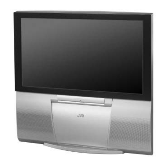
REAR PROJECTION TELEVISION
8
2006
YA455
AV-48P777
AV-56P777
TV CATV VCR
SLEEP
TIMER
THEATER PRO
VIDEO STATUS
ASPECT
SUB CH
FAVORITE
MUTING
VOL
-
MENU
VCR CHANNEL
PREV NEXT
REW
REC
OPEN/CLOSE
1
PRECAUTION. . . . . . . . . . . . . . . . . . . . . . . . . . . . . . . . . . . . . . . . . . . . . . . . . . . . . . . . . . . . . . . . . . . . . . . . . 1-3
2
SPECIFIC SERVICE INSTRUCTIONS . . . . . . . . . . . . . . . . . . . . . . . . . . . . . . . . . . . . . . . . . . . . . . . . . . . . . . 1-5
3
DISASSEMBLY . . . . . . . . . . . . . . . . . . . . . . . . . . . . . . . . . . . . . . . . . . . . . . . . . . . . . . . . . . . . . . . . . . . . . . 1-10
4
ADJUSTMENT . . . . . . . . . . . . . . . . . . . . . . . . . . . . . . . . . . . . . . . . . . . . . . . . . . . . . . . . . . . . . . . . . . . . . . . 1-20
5
TROUBLESHOOTING . . . . . . . . . . . . . . . . . . . . . . . . . . . . . . . . . . . . . . . . . . . . . . . . . . . . . . . . . . . . . . . . . 1-44
POWER
DVD
INPUT
DISPLAY
C.C.
1
2
3
4
5
6
7
8
9
TUNE
RETURN+
0
/TV
ML/MTS SOUND
GUIDE
OK
CH +
VOL
+
CH -
BACK
VCR/DVD
POWER
TV/VCR
PLAY
FF
STOP
PAUSE
STILL/PAUSE
RM-C1272G
TV
TABLE OF CONTENTS
COPYRIGHT © 2006 Victor Company of Japan, Limited
, AV-48P787
/H
, AV-56P787
/H
,
/H
/H
BASIC CHASSIS
SR2
No.YA455
2006/8

Related Manuals for JVC AV-48P777/H


Summary of Contents for JVC AV-48P777/H
-
Page 1: Table Of Contents
SERVICE MANUAL REAR PROJECTION TELEVISION YA455 2006 AV-48P777 , AV-48P787 AV-56P777 , AV-56P787 BASIC CHASSIS POWER TV CATV VCR INPUT SLEEP TIMER DISPLAY C.C. THEATER PRO VIDEO STATUS ASPECT SUB CH TUNE RETURN+ FAVORITE ML/MTS SOUND GUIDE MUTING CH + –... -
Page 2: Specification
SPECIFICATION Contents Items AV-48P777 AV-56P777 AV-48P787 AV-56P787 Dimensions (W × H × D) 120.0cm × 118.9cm × 62.2cm 136.8cm × 138.6cm × 66.7cm (47-1/4" × 46-7/8" × 24-1/2") (53-7/8" × 54-5/8" × 26-3/8") Mass 76.9kg (170 lds) 83.3kg (184 lds) TV RF System (Analog / Digital) Analog : CCIR (M) Digital : ATSC terrestrial / Digital cable... -
Page 3: Precaution
SECTION 1 PRECAUTION SAFETY PRECAUTIONS (1) The design of this product contains special hardware, many (10) Isolation Check (Safety for Electrical Shock Hazard) circuits and components specially for safety purposes. For After re-assembling the product, always perform an isolation continued protection, no changes should be made to the original check on the exposed metal parts of the cabinet (antenna design unless authorized in writing by the manufacturer. - Page 4 INSTALLATION 1.2.1 INSTALLATION SITE (1) The rear of this set is provided with ventilation openings. Install the set more than 5 cm from a wall and in a location (more than 5cm) with good ventilation. (2) Avoid the following types of locations. a) Unstable locations (location must be able to with stand heavy weight).
-
Page 5: Specific Service Instructions
Adds a more spacious surround sound. Music gives basic effect and movie for more effect. Press [3] key SELF CHECK MODE SCREEN Self Check X-RAY PHOTO HostLink <> Previous/Next Page [BACK]Back [MENU]Exit DIFFERENCE LIST Item AV-48P777/H AV-48P787/H AV-56P777/H AV-56P787/H BODY COLOR SILVER BLACK SILVER BLACK (No.YA455)1-5... -
Page 6: Technical Information
TECHNICAL INFORMATION 2.4.1 MAIN MICRO COMPUTER (CPU) FUNCTION Pin name Function Pin name Function P60/SBT2 Not used 51 ATSC_TX Serial communication for ATSC tuner P_MU O Not used : Picture muting [Muting: H] 52 ATSC_RX Serial communication for ATSC tuner M_MUTE O Audio output muting [Muting: H] 53 P85... - Page 7 MAIN PARTS LOCATION 2.5.1 PWB ASS'Y ARRANGEMENT The PWB ASS'Y is indicated below. PWB ASS'Y name AV-48P776 AV-48P786 AV-56P776 AV-56P786 ← ← 1. MAIN PWB SSR-1510A-M2 SSR-1511A-M2 ← ← ← 2. ATSC TUNER PWB SSD-2311A-M2 ← ← ← 3. POWER PWB SSR-9010A-M2 ←...
- Page 8 SCREEN HANDLING CAUTIONS 2.6.1 SCREEN STORAGE Store the SCREEN ASS'Y in a standing position in order to avoid deformation. If the screen is stored horizontally, there is risk of deforming the screen face. When necessary to place the SCREEN ASS'Y horizontally, position the screen side upwards and sure to place spacers between the screen and resting site (floor or stand etc.) to prevent the screen from sagging.
- Page 9 PROJECTION UNIT REPLACEMENT 2.7.1 ADJUSTMENT DURING REPLACEMENT When replacing the three R, G and B projection units, first replace the R and B units and perform focus / screen / raster centering adjustments with reference to the G unit. Then replace the G unit and perform G focus / screen / convergence adjustment. Finally perform R &...
-
Page 10: Disassembly
SECTION 3 DISASSEMBLY DISASSEMBLY PROCEDURE CAUTION AT DISASSEMBLY: • Be sure to perform the SYSTEM SETTEING, at the end of the procedure. • Make sure that the power cord is disconnected from the outlet. • Pay special attention not to break or damage the parts. •... - Page 11 3.1.8 REMOVING THE REAR COVER (Fig.1) • Remove the SPEAKER GRILL. • Remove the FRONT PANEL. • Remove the FRONT CONTROL BOX. • Remove the SCREEN ASS'Y. (1) Remove 2 screws [K]. (2) Remove 2 screws [L] from front side. (3) Slightly pull for backside to disengage of the REAR COVER from hooks.
- Page 12 REAR COVER MIRROR BRACKET SCREEN ASS’Y MIRROR MIRROR BRACKET PARTITION REAR PANEL FRONT FRONT CONTROL SPEAKER BODY FRONT CONTROL PWB SPEAKER SPEAKER GRILLE FRONT PANEL SPEAKER GRILLE FRONT CONTROL Fig.1 1-12 (No.YA455)
- Page 13 3.1.11 REMOVING THE MAIN UNIT (Fig.3) 3.1.14 REMOVING THE MAIN CHASSIS (Fig.2) • Remove the SPEAKER GRILL. • Remove the REAR PANEL. • Remove the FRONT PANEL. (1) Remove 2 screws [V]. • Remove the FRONTCONTROL BOX. (2) Pull out the MAIN CHASSIS for backside. •...
- Page 14 3.1.19 REMOVING THE PROJECTION UNIT (Fig.2) • Remove the SPEAKER GRILL. • Remove the FRONT PANEL. • Remove the FRONT CONTROL BOX. • Remove the REAR PANEL. • Remove the MAIN UNIT. (1) Remove the CRT SOCKET PWB. (2) Remove 4 screws [a]. (3) Pull out the PROJECTION UNIT upward.
- Page 15 MAIN UNIT BODY PROJECTION UNIT SPEAKER FRONT CONNECTOR FRONT REAR SIDE VIEW MAIN UNIT FOCUS PACK BODY MAIN CHASSIS FRONT Fig.3 DIVIDER DIGITAL CONVERGENCE MODULE PWB REMOTE SOENSOR COOLANT PAN MAIN UNIT POWER PWB MAIN PWB DEF & CONVERGENCE OUT PWB MAIN CHASSIS POWER CORD CLAMP...
- Page 16 MEMORY IC REPLACEMENT • This model uses the memory IC. • This memory IC stores data for proper operation of the video and drive circuits. • When replacing, be sure to use an IC containing this (initial value) data. 3.2.1 MEMORY IC TABLE Simbol Number of pins Mounting PWB Main content of data...
-
Page 17: Service Menu
3.2.3 SERVICE MODE SETTING ITEMS Setting items Settings Item No. Service Menu 1. Digital Service Audio system setting Adjust A001 - A010 Service Menu 1.Digital Service 2. TV-Micro Service 2.TV-Micro Service Video system setting Adjust S001 - S060 3.Conver Service 4.Diagnostics Deflection system Adjust... - Page 18 3.2.4 SETTINGS OF FACTORY SHIPMENT 3.2.4.1 BUTTON OPERATION 3.2.4.2 REMOTE CONTROL DIRECT OPERATION Setting item Setting position Setting item Setting position POWER INPUT CHANNEL CABLE-02 CHANNEL CABLE-02 VOLUME VOLUME MUTING DISPLAY SLEEP TIMER VIDEO STATUS DYNAMIC THEATER PRO C.C. STEREO ASPECT PANORAMA A.H.S.
- Page 19 REPLACEMENT OF CHIP COMPONENT 3.3.1 CAUTIONS (1) Avoid heating for more than 3 seconds. (2) Do not rub the electrodes and the resist parts of the pattern. (3) When removing a chip part, melt the solder adequately. (4) Do not reuse a chip part after removing it. 3.3.2 SOLDERING IRON (1) Use a high insulation soldering iron with a thin pointed end of it.
-
Page 20: Adjustment
SECTION 4 ADJUSTMENT ADJUSTMENT PREPARATION (1) You can make the necessary adjustments for this unit with SETTING POSITION either the Remote Control Unit or with the adjustment tools Setting item Setting position and parts as given below. VIDEO STATUS STANDARD (2) Adjustment with the Remote Control Unit is made on the TINT / COLOR / PICTURE / basis of the initial setting values, however, the new setting... - Page 21 BASIC OPERATION OF SERVICE MENU SERVICE MENU 4.Diagnostics Service Menu 1.Digital Service [Refer to SECTION 5] 1. Digital Service 2.TV-Micro Service 3.Conver Service 4.Diagnostics Digital Service 1.Adjust 2.Memory Edit 3. Conver Service 2. TV-Micro Service 3.Edit Config 4.All Reset 5.Select Channel Map TV-Micro Service Conver Service 6.Clear Channel Map...
- Page 22 SERVICE MODE 4.5.1 BASIC OPERATION OF SERVICE MODE Operate the SERVICE MODE with the REMOTE CONTROL UNIT. 4.5.1.1 HOW TO ENTER THE SERVICE MODE 4.5.1.4 SERVICE MODE SELECT KEY LOCATION (1) Set to "0 minutes" using the [SLEEP TIMER] key. (2) While "0 minutes"...
- Page 23 4.5.2 DESCRIPTION OF STATUS DISPLAY The status display on the upper part of the SERVICE MODE screen is common (to all models). 4.5.2.1 DIGITAL SERVICE MODE 1. Adjust (4) WHITE BALANCE State of the WHITE BALANCE is displayed. H : HIGH SETTING ITEM No.
- Page 24 3. Edit Config 6. Clear Channel Map Setting value in the digital module is edited and confirmed on Channel map is cleared on this screen. [Do not adjust] this screen. [Do not adjust] CAUTION: CAUTION: This mode is not used in the ADJUSTMENT. Press the This mode is not used in the ADJUSTMENT.
- Page 25 4.5.2.2 TV-MICRO SERVICE MODE 1. Adjust (5) SETTING ITEM NAME Setting item name are displayed. For the setting item names to be displayed, refer to "INITIAL SETTING VALUE OF SETTING ITEM No. SETTING VALUE (DATA) SETTING ITEM SERVICE MODE". (6) SETTING ITEM NO. S001 BRIGHT Setting item numbers are displayed.
- Page 26 2. White Balance 3. Memory Edit White balance data is adjusted on this screen. Data in the EEPROM is edited on this screen. [Do not adjust] CAUTION: This mode is not used in the ADJUSTMENT. Press the SETTING VALUE (DATA) [BACK] key to return to the SERVICE MENU SCREEN.
- Page 27 4.5.2.3 CONVER SERVICE MODE 2. Fine Adjust Setting the CONVERGENCE POINT (fine). 1. Coarse Adjust • This setting described CONVERGENCE Setting the CONVERGENCE PHASE and LINE (coarse) adjustment. adjustment. • This setting is described in the CONVERGENCE FINE ADJUST MODE adjustment.
- Page 28 INITIAL SETTING VALUE OF SERVICE MODE (1) Adjustment of the SERVICE MODE is made on the basis of the initial setting values ; however, the new setting values which set the screen in its optimum condition may differ from the initial setting. (2) Do not change the initial setting values of the setting items NOT LISTED IN ADJUSTMENT PROCEDURE.
- Page 29 Initial setting value RF/EXTERNAL(S/CV) EXTERNAL(COMPONENT)/ATSC/HDMI Variable Setting item range STANDARD THEATER STANDARD THEATER HIGH HIGH HIGH HIGH S011 R CUTOFF 000 - 063 S012 G CUTOFF 000 - 063 S013 B CUTOFF 000 - 063 S014 R DRIVE 000 - 063 S015 B DRIVE 000 - 063...
- Page 30 Initial setting value Variable Setting item Initial setting value range Variable Full Setting item range Cinema Panorama S040 SHP CD 000 - 003 Regular S041 CD OFF 000 - 001 D020 H CENT 000 - 063 S042 VM LEV 000 - 003 D021 H CENT+- -128 - +127...
- Page 31 Initial setting value Variable Setting item Initial setting value Variable range Full Setting item range Cinema Panorama CDA01 DF DC -512 - 511 Regular CDA02 DF H1 -512 - 511 D064 HCPR PH 000 - 063 CDA03 DF H2 -512 - 511 D065 HCPR AMP 000 - 063...
- Page 32 Variable Variable Setting item Initial setting value Setting item Initial setting value range range CBA37 CURSOR COL 0 - 7 CBA82 SQ7VSIZE 0 - 255 CBA38 CROSS COL 0 - 7 CBA83 SQ7HSIZE 0 - 255 CBA39 SQUARE COL 0 - 7 CBA84 SQ8POSV 0 - 2047...
- Page 33 ADJUSTMENT PROCEDURE 4.7.1 CHECK ITEMS Measuring Item Test point Adjustment part Description instrument X-RAY Resistor S1 connector (1) Receive NTSC whole black signal. PROTECTOR [6.8kΩ±34Ω 2 pin : X-Ray2 (2) Connect resistor 6.8kΩ±34Ω (1/4W) between 2 pin check (1/4W) ] 3 pin : X-Ray1 and 3 pin of the S1 connector.
- Page 34 4.7.2 FOCUS & BEAM SPOT ADJUSTMENT Measuring Item Test point Adjustment part Description instrument FOCUS & Similar Conver Service (1) Select FULL mode with [ASPECT] key. BEAM SPOT adhesive [3. Conver Off] (2) Select DYNAMIC mode with [VIDEO STATUS] key. adjustment (Securing (3) Select 3.
- Page 35 4.7.3 DEFLECTION & CONVERGENCE ADJUSTMENT • The adjustment using the remote control unit is made on the basis of the initial setting values. • The setting values which adjust the screen to the optimum condition can be different from the initial setting values. •...
- Page 36 4.7.3.2 PREPARATION Measuring Item Test point Adjustment part Description instrument SCREEN TILT Remote Conver Service • Confirm correct FOCUS adjustment. (1) Enter Conver Service [3. Conver Off]. adjustment control unit [3. Conver Off] (2) Select crosshatch pattern with [INPUT] key. (3) Make a green single color.
- Page 37 4.7.3.3 DEFLECTION ADJUSTMENT [2. TV-Micro Service] Measuring Item Test point Adjustment part Description instrument V. POSITION / Signal [1. Adjust] • To memorize every time after finish adjustment on each V.SIZE / generator D001 : V. SIZE mode. V.LINEARITY D009 : V. LIN (1) Receive NTSC circle pattern signal.
- Page 38 Measuring Item Test point Adjustment part Description instrument SIDE PIN Signal [1.Adjust] (1) Receive NTSC crosshatch signal. adjustment generator D003 : EW (2) Select FULL mode with [ASPECT] key. D014 : BOT.CORN (3) Switch off the convergence circuit. Remote D016 : TOP.CORN (4) Enter TV-Micro Service [1.
-
Page 39
4.7.3.4 CONVERGENCE ADJUSTMENT [3. Conver Service] Measuring Item Test point Adjustment part Description instrument CONVERGENCE Remote [1.Coarse Adjust] (1) Enter Conver Service [1. Coarse Adjust]. PHASE control unit CPA02 : TPOPH (2) Select
item with [INPUT] key. check CPA03 : TPOPV LINE (3) Check and set data that ... - Page 40 4.7.4 VIDEO ADJUSTMENT [2. TV-Micro Service] Measuring Item Test point Adjustment part Description instrument RGB CUTOFF Signal TP-R [1. Adjust] (1) Receive NTSC signal (include 3% black). adjustment generator [R CRT S001 : BRIGHT (2) Select STANDARD mode with [VIDEO STATUS] SOCKET PWB] S011 : R CUTOFF key.
- Page 41 Measuring Item Test point Adjustment part Description instrument WHITE Signal [1.Adjust] • WHITE BALANCE(LOW LIGHT) adjustment should be BALANCE generator S014: R DRIVE finished. (HIGH LIGHT) S015: B DRIVE (1) Receive the NTSC black and white signal (color off). adjustment Remote (2) Select STANDARD mode with [VIDEO STATUS] control unit...
- Page 42 Measuring Item Test point Adjustment part Description instrument SUB COLOR / Remote [1.Adjust] [ Method of adjustment without measuring instrument ] SUB TINT control unit S003 : COLOR (1) Receive any broadcast. adjustment (1) S004 : TINT (2) Select STANDARD mode with [VIDEO STATUS] key.
-
Page 43
4.7.5 MTS ADJUSTMENT [1. Digital Service] Measuring Item Test point Adjustment part Description instrument MTS INPUT Remote [1.Adjust] (1) Receiv any broadcast. LEVEL control unit A001: IN LEVEL (2) Enter Digital Service [1. Adjust]. adjustment (3) Select the
(IN LEVEL). (4) Set the intal setting value of the . -
Page 44: Troubleshooting
SECTION 5 TROUBLESHOOTING SELF CHECK FEATURE 5.1.1 OUTLINE This unit comes with the "Self check" feature, which checks the SERVICE MENU SCREEN operational state of the circuit and displays/saves it during Service Menu failure. Diagnosis is performed when power is turned on, and 1.Digital Service information input to the main microcomputer is monitored at all 2.TV-Micro Service... - Page 45 5.1.6 DETAILS Self check is performed for the following items: 5.1.6.1 PAGE 1 OF SCREEN Diagnosis Detection item Display Detection content Detection timing signal (line) X-ray protection X-RAY Operation of X-ray protection circuit. X_RAY At about 3 seconds after the power is Q710 [MAIN PWB] turned on, the self-check function starts.
- Page 46 5.1.7 DISPLAY METHOD WHEN RASTER IS NOT AVAILABLE The self check results are shown on the following POWER LED display. When the raster is not displayed, each failure is shown by turning LED on and off at the specified intervals. •...
- Page 47 Victor Company of Japan, Limited Display Category 12, 3-chome, Moriya-cho, Kanagawa-ku, Yokohama-city, Kanagawa-prefecture, 221-8528, Japan (No.YA455) Printed in Japan...