Table of Contents
SERVICE MANUAL
Ver 1.0 2004.06
AVD-K150B/K150E/K150G/K150N/K150R is the
Amplifier, DVD/VIDEO player and tuner section
in DAV-D150B/D150E/D150G/D150N/D150R.
• Manufactured under license from Dolby Laboratories. "Dolby", "Pro
Logic", and the double-D symbol are trademarks of Dolby Laboratories.
Confidential unpublished works. Copyright 1992 -1997 Dolby
Laboratories. All rights reserved.
• DTS and DTS Digital Surround are registered trademarks of Digital
Theater Systems, Inc.
General
Power requirements
AC 230 V , 50/60 Hz
Power consumption
74W
Dimensions (approx.)
430 x 98 x 386 mm
x 15
Mass (approx.)
6.5 kg (14 lb 6 oz)
5 ° C to 35 ° C (41 ° F to 95 ° F)
Operating temperature
Operating humidity
5 % to 90 %
DVD Section
Laser
Semiconductor laser (Wavelength
DVD: 650nm, CD: 780nm)
Signal system
PAL
Frequency response
DVD (PCM 48 kHz): 10 Hz to 22 kHz
CD: 10 Hz to 20 kHz
Signal-to-noise ratio
More than 80 dB (ANALOG OUT
connectors only)
Harmonic distortion
Less than 0.05%
VIDEO Section
Head system
4 heads helical scan azimuth system
Television system
PAL B/G colour system (150E)
PAL B/G, SECAM L colour system (150B)
PAL I colour system (150G)
PAL B/G, SECAM D/K colour system (150N)
PAL (B/G, I/I), SECAM D/K colour system (150R)
Recording format
PAL
Tape speed
PAL/MESECAM; 23.39 mm/s (SP),
16.69 mm/s (LP)
Sony Corporation
9-877-959-01
Home Audio Company
2004F1678-1
Published by Sony Engineering Corporation
© 2004.06
AVD-K150B/K150E/K150G/
SPECIFICATIONS
(17 x 3
7
/
8
1
/
inches) (W x H x D)
4
K150N/K150R
Model Name Using Similar Mechanism NEW
DVD
Mechanism Type
Optical Pick-up Name
VCR
Mechanism Type
Maximum recording time
SP: 4 hour (E-240 tape), LP: 8 hour
(E-240 tape)
Rewind time
About 180 seconds (E-180 tape)
Input level
VIDEO: 1.0 V(p-p), 75 ohms, unbalanced
AUDIO: -6.0 dBm, more than 10 kohms (SCART)
DIGITAL AUDIO IN: Optical connector x 1
Output level
VIDEO: 1.0 V(p-p), 75 ohms, unbalanced
FM Tuner
Tuning Range
65 - 74 MHz (150R)
87.5 - 108.0 MHz (ALL MODEL)
Intermediate Frequency
10.7 MHz
AM Tuner
Tuning Range
522 - 1,611 kHz
Intermediate Frequency
450 kHz
Amplifier Section
70W + 70W (6 Ω at 1 kHz, THD 10 %)
Stereo mode
Front: 70W/ch (6 Ω at 1 kHz, THD 10 %)
Surround mode
Center*: 70W (6 Ω at 1 kHz, THD 10 %)
Surround*: 70W/ch (6 Ω at 1 kHz, THD 10 %)
Subwoofer*: 100W (4 Ω at 30 Hz, THD 10 %)
* Depending on the sound mode settings and the source,
there may be no sound output.
Inputs
AV 2, AV 3, OPTICAL IN (AV3 OPT)
• Design and specifications are subject to change without notice.
AEP Model
AVD-K150B/K150E/K150N/K150R
UK Model
AVD-K150G
DP-7C
PVR-502W
D35 (N)
-6.0 dBm, more than 47 kohms (RCA)
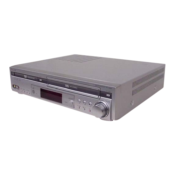
DVD/VCR RECEIVER
Table of Contents
Troubleshooting

Related Manuals for Sony AVD-K150B


Summary of Contents for Sony AVD-K150B
- Page 1 AV 2, AV 3, OPTICAL IN (AV3 OPT) Tape speed PAL/MESECAM; 23.39 mm/s (SP), 16.69 mm/s (LP) • Design and specifications are subject to change without notice. DVD/VCR RECEIVER Sony Corporation 9-877-959-01 Home Audio Company 2004F1678-1 Published by Sony Engineering Corporation © 2004.06...
- Page 2 COMPONENTS IDENTIFIED BY MARK 0 OR DOTTED LINE WITH MARK 0 ON THE SCHEMATIC DIAGRAMS AND IN THE PARTS LIST ARE CRITICAL TO SAFE OPERATION. REPLACE THESE COMPONENTS WITH SONY PARTS WHOSE PART NUMBERS APPEAR AS SHOWN IN THIS MANUAL OR IN SUPPLEMENTS PUBLISHED BY SONY.
- Page 3 AVD-K150B/K150E/K150G/K150N/K150R • SERVICE POSITION-1 (DVD Mechanism Deck) Extension cable (J-2501-242-A, J-2501-245-A) is required to inspect the DVD mechanism deck. DVD mechanism deck J-2501-245-A (1mm/23P/L300) J-2501-242-A (1mm/11P/L300) • SERVICE POSITION-2 (VIDEO Mechanism Deck) Perform the operation check of the VIDEO mechanism deck after the VCR board and the VIDEO mechanism deck are turned upside down.
-
Page 4: Table Of Contents
AVD-K150B/K150E/K150G/K150N/K150R TABLE OF CONTENTS GENERAL 5-13. Schematic Diagram – AUDIO, _COM Section – ..............5 [DVD & AMP Board] (3/6) ..........64 5-14. Schematic Diagram – DIGITAL AMP Section – DISASSEMBLY [DVD & AMP Board] (4/6) ..........65 2-1. Cover, Front Panel Assembly .......... 12 5-15. -
Page 5: General
AVD-K150B/K150E/K150G/K150N/K150R SECTION 1 GENERAL This section is extracted from instruction manual. Front Panel A VIDEO @ / 1 Ejects the tape in the VIDEO deck. Switches the DVD/VCR Receiver ON and OFF. AV 3 IN (VIDEO/AUDIO (Left/Right)) VOLUME Connect the audio/video output of an Adjusts sound level of speakers. -
Page 6: Display Window
AVD-K150B/K150E/K150G/K150N/K150R Display Window SHUFFLE RANDOM playback active SP LP Displays the recording and playback speed. Indicates repeat mode A cassette is in the VIDEO deck. PGM Programmed playback active. BIL Indicates when a BILINGUAL broadcast is being received. STEREO Indicates a stereo broadcast is being received. -
Page 7: Remote Control
AVD-K150B/K150E/K150G/K150N/K150R Remote Control VIDEO TV @ / 1 Select the output source to VIDEO. Switches TV ON and OFF. @ / 1 Sets the output source to DVD. Switches DVD/VCR Receiver ON and OFF. INPUT SELECT TV Control Buttons (see page 41) •... -
Page 8: Rear Panel
AVD-K150B/K150E/K150G/K150N/K150R Rear Panel FM ANTENNA Connectors Connect the FM antenna to this terminal. SPEAKERS Connectors Connect the six supplied speakers to these terminals. EURO AV2 DECODER/EXTERNAL (VIDEO IN) Connect to Pay-TV decoder, Set Top Box or another video recorder. AC Power Cord Plug into the power source. - Page 9 AVD-K150B/K150E/K150G/K150N/K150R Connections TV and Decoder (or Set Top Box) Connections Make one of the following connections, depending on the capabilities of your existing equipment. SCART INPUT AERIAL Rear of TV Tips Basic connection (RF) • Depending on your TV and other equipment you wish...
-
Page 10: Radio Aerial Connections
AVD-K150B/K150E/K150G/K150N/K150R Connections (Continued) Radio Aerial Connections Digital Device Connections Connect the OPTICAL IN jacks on the DVD/VCR Connect the supplied FM/AM antennas for radio listen- Receiver to the digital audio out (optical) jacks on your ing. digital device (Game device, Digital Set Top Box, etc.), Connect the AM loop antenna to the AM antenna using optional optical audio cable. -
Page 11: Speaker System Connections
AVD-K150B/K150E/K150G/K150N/K150R Connections (Continued) Speaker System Connections Speaker Positioning Connect the speakers using the supplied speaker cords For a normal setup use 6 speakers (2 front speakers, by matching the colors of the terminals and those of the center speaker, 2 rear speakers and subwoofer). -
Page 12: Disassembly
AVD-K150B/K150E/K150G/K150N/K150R SECTION 2 DISASSEMBLY • This set can be disassembled in the order shown below. • The dotted square with arrow ( ) prompts you to move to the next job when all of the works within the dotted square ) are completed. -
Page 13: Display/Key Board
AVD-K150B/K150E/K150G/K150N/K150R 2-2. DISPLAY/KEY BOARD 1 t hree claws 4 DISPLAY/ KEY board 2 four claws 3 connector ( PM602,PM601 ) 2-3. VIDEO MECHANISM DECK ix screws 4 VIDEO m echanism deck 2 fl exible cable 3 connector PMCO1... -
Page 14: Dvd Mechanism Deck
AVD-K150B/K150E/K150G/K150N/K150R 2-4. DVD MECHANISM DECK 2 two screws shield cover 1 two screws flexible cable (PMD01) flexible cable (PMD03) DVD mechanism deck door case 2-5. SMPS BOARD four screws shield connector (PSW01) connector (PSV01) connector (PW101) 7 SMPS board 6 screw (3 × 10 ) -
Page 15: Vcr Board
AVD-K150B/K150E/K150G/K150N/K150R 2-6. VCR BOARD 6 connector (PDV01) 1 four screws q; three screws 4 bracket 7 flexible cable (PVD02) 8 flexible cable (PVD03) 2 connector (PVS01) 5 VCR-DISPLAY pwb holder qs VCR board 9 screw 3 screw qa two claws 2-7. -
Page 16: Electrical Adjustments
AVD-K150B/K150E/K150G/K150N/K150R SECTION 3 ELECTRICAL ADJUSTMENTS 3-1. VCR SECTION ELECTRICAL ADJUSTMENT 1. Servo Adjustment 1) PG Adjustment • Test Equipment a) OSCILLOSCOPE b) NTSC MODEL : NTSC SP TEST TAPE • Adjustment And Specification MODE MEASUREMENT POINT ADJUSTMENT POINT SPECIFICATION V.Out 6.5 ±... -
Page 17: Electrical Troubleshooting Guide
AVD-K150B/K150E/K150G/K150N/K150R 3-2. ELECTRICAL TROUBLESHOOTING GUIDE 1. Power (SMPS) CIRCUIT (1) No 5.3VA (SYS/Hi-Fi/TUNER) (2) No 12VA (TO CAP, DRUM MOTOR) NO 5.3VA. NO 12VA. Replace the F101. Is the Vcc(13V) supplied Check or Replace Is the F101 normal? (Use the same Fuse) to (+) terminal in D115? the D110. - Page 18 AVD-K150B/K150E/K150G/K150N/K150R (4) No 5V (TO DVD) (5) No 33V (TUNER) NO 5V. No 33V. Is 5.3VA put into Check the Power 5.3VA Line Check. Is Q163 Base “H”? the Q160 Emitter? Control. Is the Q162 Base Check the Power Check or Replace “H”?
- Page 19 AVD-K150B/K150E/K150G/K150N/K150R 2. SYSTEM/KEY CIRCUIT (1) AUTO STOP Auto Stop Does the SW25 waveform Check the Drum Motor appear at the IC501 signal. Pin105? Do T/UP Reel Pulses Do the T-UP Reel Pulses Does 5.2V appear at the appear at the Q514...
- Page 20 AVD-K150B/K150E/K150G/K150N/K150R 3. SERVO CIRCUIT (1) Unstable Video in PB MODE Unstable Video in PB Mode. Does the Noise level of the screen change periodically? Do the CTL pulses appear Is adjusting the height of at the IC501 Pin8? the CTL Head accurate?
- Page 21 AVD-K150B/K150E/K150G/K150N/K150R (3) When the Capstan Motor doesn’t run, When the Capstan Motor doesn’t run, Refer to “SMPS(CAPSTAN/12Volt) Does 12VA appear at the PMC01? Trouble Shooting”. Does 2.8V appear at the PMC01? Check the PMC01 and the Capstan Does the PWM signal appear at the IC501 Pin108? Motor Ass’y.
- Page 22 AVD-K150B/K150E/K150G/K150N/K150R (4) KEY doesn’t working KEY doesn’t working. Is 5V applied to the IC501 Refer to “SMPS 5.3VA Pin36? Trouble Shooting”. Does LED or FLD change Replace the defective when a function button is switches. pressed?
- Page 23 AVD-K150B/K150E/K150G/K150N/K150R 4. Y/C CIRCUIT (1) No Video in EE Mode, No Video in EE Mode Does the Video signal Check the 24Pin of Tuner. appear at the IC301 Pin48? Is 5V applied to the IC301 Check the 5.2VT, 5.3VA Pins18, 24, 42, 55, 72, 91? Line.
- Page 24 AVD-K150B/K150E/K150G/K150N/K150R 3. Y/C CIRCUIT (2) When the Y(Luminance) signal doesn’t appear on the screen in PB Mode, Is 5.2VT, 5.3VA applied to the Check the line of the 5.2VT, 5.3VA Line. (Power Circuit) IC301 Pins24, 42, 55, 72, 91? Is the I C Bus siganl applied Refer to ‘SYSTEM I...
- Page 25 AVD-K150B/K150E/K150G/K150N/K150R 3. Y/C CIRCUIT (3) When the C(Color) signal doesn’t appear on the screen in PB Mode, Is 5.2VT/5.3VA applied to the Check the line of the 5.2VT/ 5.3VA Line. (Power Circuit) IC301 Pins24, 42, 55, 72, 91. Is the Color Rotary signal...
- Page 26 AVD-K150B/K150E/K150G/K150N/K150R 3. Y/C CIRCUIT (4) When the Video signal doesn’t appear on the screen in REC Mode, Is the EE signal normal? Check EE Mode. Is 5.2VT/5.3VA applied to the Check the line of the 5.2VT/ IC301 Pins24,42,55,72,91? 5.3VA Line.(Power Circuit) Does PB Mdoe operate Check PB Mode.
- Page 27 AVD-K150B/K150E/K150G/K150N/K150R 5. Hi-Fi CIRCUIT (A) No Sound(EE Mode) No Sound. Check the TU Audio of IC801 Check the IC751 Pins30, 31. Pins1, 3. Check the DVD Audio of IC801 Check the DVD MODULE. (P8D01 Pins3, 5). Pins4, 5. Check the AV1 Audio of IC801 Check the Scart1 Jack.
- Page 28 AVD-K150B/K150E/K150G/K150N/K150R 3. Y/C CIRCUIT (B) Hi-Fi Playback PB mode No Sound. Check the Vcc of IC801 Check Power 5.2V, 12VT. (Pins34, 40) Check the Hi-Fi Selection switch. Check IC501 Pin25 (A.H/SW) (IC801 Pin41) and the Tape quality. Is the RF Envelope at IC801 Pin44 over 2Vp-p? Check the parts of µ-COM...
- Page 29 AVD-K150B/K150E/K150G/K150N/K150R Hi-Fi REC. It is impossible to record Hi-Fi Audio signal. Check Vcc of IC801.(Pins34, 40) Check Power 5V, 12VT. Check ports of µ-COM. Check IC801 Pin42(Data), Pin43(CLOCK). Check Audio input signal of IC801 Do Audio signals appear at IC801 Pins2, 3(TU.A.), 4, 5(DVD.A.),...
- Page 30 AVD-K150B/K150E/K150G/K150N/K150R 6. Tuner/IF CIRCUIT (A) No Picture on the TV screen No picture on the TV screen Does the Video signal at Is +33V applied to TU701 Check 33V line. the TU701 Pin24. Pin16? Is +5V applied to TU701 Check 5V line.
- Page 31 AVD-K150B/K150E/K150G/K150N/K150R (B) No Sound No Sound. Check the Vcc of IC751 Pins1, 11, 19, Check 5.2V Line. 22, 33. Check the Tuner SiF signal at IC751 Check the Tuner SIF of TU701 Pin22. Pin2. Check the oscillator of IC751 Pins5, 6.
-
Page 32: Dvd & Amp Section Electrical Troubleshooting Guide
AVD-K150B/K150E/K150G/K150N/K150R 3-3. DVD & AMP SECTION ELECTRICAL TROUBLESHOOTING GUIDE 1. System operation flow Power On 1. 8032 initializes SERVO, DSP & RISC registers 2. Write RISC code to SDRAM 3. Reset RISC Show LOGO Tray Closed? Tray Close to Closed position... - Page 33 AVD-K150B/K150E/K150G/K150N/K150R 2. T est & debug flow TEST Check the AC Voltage Check the POWER PART Power PCBA (110V or 220V) Switch on the Power PCBA the DC Voltage outputs OK? Check the POWER PART (5V, 3.3V, 8V, 12V) Is 3.3V and 2.5V DC Check the regulators or diode(D501).
- Page 34 AVD-K150B/K150E/K150G/K150N/K150R RESET or Power On. Flash Check connection lines between FLASH Memory operates Show LOGO? & MT1379 and the FLASH access time properly? whether is sui table or not. Check connection lines between SDRAM SDRAM(IC502,IC503) & MT1379 and the works properly? SDRAM is damaged.
- Page 35 AVD-K150B/K150E/K150G/K150N/K150R Does the SLED move Check the connection line of Motor Driver STBY to inner side when it is at STBY signal . Pin is High? outer position? Check the related circuit of Motor Driver STBY FMSO. Pin is High?
- Page 36 AVD-K150B/K150E/K150G/K150N/K150R Check the laser power circuit Laser turns on when LD01 or LD02 output on MT1336 and connecting to reading disc? properly? power transistor. (Q404, Q405) Collector voltage of power Check the related circuit on transistor is OK? laser power transi stor...
- Page 37 AVD-K150B/K150E/K150G/K150N/K150R Proper Check connections between signals on A, B, C, Focus ON OK? MT1336 and pick-up head. D of MT1336 Check the related circuit Proper FEO signal on MT1336 FEO sugnal . on MT1336? Check FEO connection between MT1336 and MT1379...
- Page 38 AVD-K150B/K150E/K150G/K150N/K150R Audio Normal DAC received Check connection between MT1379 Audio output correct data stream? & Audio DAC. (Check ARCK, ALRCK when disc playback? ACKL, ASDAT3) Normal Check the related circuit of Audio DAC Audio DAC. (Check Audio out? (IC206) out Pins 8, 5) Check Audio filter, amplify, mute circuit.
- Page 39 AVD-K150B/K150E/K150G/K150N/K150R 3. AUDIO µ -COM Circuit(DVD & AMP) POWER ON Does CD/DVD appear Does CD/DVD appear at FLT? at FLT? Does Loading appear Does it appear DVD Error at FLD? at FLD? Does no Dise or Time Check Connector (DVV01) Reconnet it.
-
Page 40: Mechanical Adjustments
AVD-K150B/K150E/K150G/K150N/K150R SECTION 4 MECHANICAL ADJUSTMENTS • Tools and Fixfures for Service 1. Cassette Torque meter 2. Alignment tape 3. Torque gauge SRK-VHT-303(Not SVC part) (See figure below) 600g.Cm ATG 4. Torque gauge adaptor 5. Post height adjusting driver 6. + Type driver (φ 5) Parts No. -
Page 41: Mechanism Alignment Position Check
AVD-K150B/K150E/K150G/K150N/K150R 1. Mechanism Alignment Position Check Purpose:To determine if the Mechanism is in the correct position, when a Tape is ejected. Test Conditions (Mechanism Test Equipment/ Fixture Check Point Condition) • Mechanism and Mode Switch Position • Blank tape • Eject Mode (with Cassette ejected) -
Page 42: Checking Torque
AVD-K150B/K150E/K150G/K150N/K150R cassette without tape. 2. Preparation for Adjustment (To set the Cover the holes of the End Sensors at the both sides of Deck Mechanism of the loading state the Chassis to prevent a light leak. without inserting a cassette tape). -
Page 43: Guide Roller Height Adjustment
AVD-K150B/K150E/K150G/K150N/K150R 4.Guide Roller Height Adjustment Purpose: To regulate the height of the tape so that the bottom of the tape runs along the tape guide line on the Lower Drum. 4-1. Preliminary Adjustment Test Equipment/ Fixture Test Conditions (Mechanism Condition) Adjustment Point •... - Page 44 AVD-K150B/K150E/K150G/K150N/K150R 5. Audio/Control (A/C) Head Adjustment Purpose: To insure that the tape passes accurately over the Audio and Control Tracks in exact alignment of the both Record and Playback Modes. 5-1. Preliminary Adjustment (Height and Tilt Adjustment) Perform the Preliminary Adjustment, when there is no Audio Output Signal with the Alignment Tape.
- Page 45 AVD-K150B/K150E/K150G/K150N/K150R 5-2. Confirm that the tape passes smoothly (2) If folding or curling is observed at the top of it then slowly turn the Tilt Adjustment Screw(C) in the between the Take-up Guide and Pinch counterclockwise direction. Roller(using a mirror or the naked eye).
- Page 46 AVD-K150B/K150E/K150G/K150N/K150R 7. Adjustment after Replacing Drum Assembly (Video Heads) Purpose: To correct for shift in the Roller Guide and X value after replacing the Drum. Test Conditions Test Equipment/ Fixture Connection Point Adjustment Points (Mechanism Condition) • CH-1: PB RF Envelope •...
-
Page 47: Check Before Starting Repairs
AVD-K150B/K150E/K150G/K150N/K150R 1. Check before starting repairs The following faults can be remedied by cleaning and oil- ing. Check the needed lubrication and the conditions of cleanliness in the unit. Check with the customer to find out how often the unit is used, and then determine that the unit is ready for inspec- tion and maintenance. -
Page 48: Required Maintenance
AVD-K150B/K150E/K150G/K150N/K150R 2. Required Maintenance 4. Supplies Required for Inspection and Maintence The recording density of a VCR(VCP) is much higher than that of an audio tape recorder. VCR(VCP) components must (1) Grease : Kanto G-311G (Blue) or equivalent be very precise, at tolerances of 1/1000mm, to ensure com- (2) Isopropyl Alcohol or equivalent patibility with the other VCRs. - Page 49 AVD-K150B/K150E/K150G/K150N/K150R 5-2) Greasing (2) Periodic greasing Grease specified locations every 5,000 hours. (1) Greasing guidelines 1) Loading Path Inside & Top side 6) Plate Slider Guide Sections Apply grease, with a cleaning patch. Do not use exces- 2) Base Assembly P2,P3 stopper 7) Plate Slider Guide Sections sive grease.
- Page 50 AVD-K150B/K150E/K150G/K150N/K150R Lever, F/R, Base, Tension GEAR AY, P2 & P3 Boss Lever, F/R Base, Tension Clutch (G-754. Yellow) Arm Tension Guide Hole...
-
Page 51: Diagrams
AVD-K150B/K150E/K150G/K150N/K150R SECTION 5 DIAGRAMS • Circuit Boards Location THIS NOTE IS COMMON FOR PRINTED WIRING BOARDS AND SCHEMATIC DIAGRAMS. (In addition to this, the necessary note is printed in each block.) DVD & AMP board For schematic diagrams. For printed wiring boards. -
Page 52: Block Diagram - Dvd (Overall) Section
AVD-K150B/K150E/K150G/K150N/K150R 5-1. BLOCK DIAGRAM – DVD (OVERALL) SECTION – DISC DV33 SD33 SD33 IC502 IC503 IC5A1 Signal Path DVD:RF0,A,B,C,D HY57V161610DTC-7 HY57V161610DTC-7 CD:RF0,A,B,C,D,E,F SDRAM PICK MDI1 SDRAM SDRAM SPINDLE : AUDIO LD01,LD02, IOA, V2.0 MOTOR : CD : DVD SLED LOADING... -
Page 53: Block Diagram - Dvd (Amp) Section
AVD-K150B/K150E/K150G/K150N/K150R 5-2. BLOCK DIAGRAM – DVD (AMP) SECTION – 12.288MHz 3.3V FRONT R 56/57 31/32 2,3/8,9 REAR R IC710 29/30 53/54 RESET STA505 FRONT L 70/71 DIGITAL AMP 505_PDN REAR L 67/68 10,11/16,17 CENTER 505_TH_WAR 63/64 S/WOOFER IC301 60/61 PS9702B... -
Page 54: Block Diagram - Vcr/Panel Section
AVD-K150B/K150E/K150G/K150N/K150R 5-3. BLOCK DIAGRAM – VCR/PANEL SECTION – LD(+) LD(-) OTPB LED 'H' IC501 CANAL DET 'H' HD6432197SA SYSTEM L/M CONTROL CONTROLLER R525, R526 R/C IN(2W) FLDRIVER BUFFER CST SW IC601 IC506 uPD16315 MM74HCT244 2fsc R524, R514, R518, R516, R589, C577,... -
Page 55: Block Diagram - Vcr (Y/C) Section
AVD-K150B/K150E/K150G/K150N/K150R 5-4. BLOCK DIAGRAM – VCR (Y/C) SECTION – (PB MODE) (REC MODE) 68 67 SECAM CHROMA 60dB AMP IC201(2/2) LA70100M PB FM MAIN SUB LPF V.IN2 S1 DE EMP EMPHA CLIP Y/C MIX V.IN1 TUNER Y-LPF DETAIL PB FM EQ... -
Page 56: Block Diagram - Vcr (Tu-Vps) Section
AVD-K150B/K150E/K150G/K150N/K150R 5-5. BLOCK DIAGRAM – VCR (TU-VPS) SECTION – TUIF,NICAM&A2 BLOCK VPS BLOCK 5.2VA 11 10 NICAM/A2 DEMODULATOR MSP3417 DATA/SYNV DATA SLICER AQUISITION CLOCK PLL IC7V1 SDA5650 VPS DECODER IIC BUS TIMING INTERFACE DA VIN DATA Signal Path : TUNER... -
Page 57: Block Diagram - Vcr (Hi-Fi) Section
AVD-K150B/K150E/K150G/K150N/K150R 5-6. BLOCK DIAGRAM – VCR (HI-FI) SECTION – VIDEO INPUT BLOCK Hi-Fi/ AUDIO INPUT 36 35 BLOCK Tu A.IN 'L' 28 29 A.OUT 'L' Tu A.IN 'R' A.OUT DVD A.IN 'L' A.OUT 'R' IC802 To JACK IC801 DVD A.IN 'R' AV1 A.IN 'L'... -
Page 58: Block Diagram - Vcr Power Section
AVD-K150B/K150E/K150G/K150N/K150R 5-7. BLOCK DIAGRAM – VCR POWER SECTION – TO SYS FD(+) TO SYS FD(-) TO SYS -29VA Q163 TO TU SWITCH 33VT PVD01 IC160 FD(+) 5.3VA 8V REG FD(-) -29VA 33VA 3.3V 3.3V IC161 13VA 3.3V REG Q168 SWITCH 3.8VA... -
Page 59: Block Diagram - Power Section
AVD-K150B/K150E/K150G/K150N/K150R 5-8. BLOCK DIAGRAM – POWER SECTION – PSW01 T101 BD101 32VA BD101 RECTIFER & SMOOTHING 12VA BLOCK C103 PWR SENSE ( D122, C131, R131, C132, C133, C135, L122 ) IC101 DEFECTOR FEED-BACK BLOCK ( R122, R121, C136, PWR SENSE... -
Page 60: Printed Wiring Board - Dvd & Amp Section (Component Side)
AVD-K150B/K150E/K150G/K150N/K150R 5-9. PRINTED WIRING BOARD – DVD & AMP SECTION (COMPONENT SIDE) – See page 51 for Circuit Boards Location. [DVD& BOARD](COMPONENT SIDE) IC104 IC101 • Semiconductor Location IC301 Ref. No. Location D501 D603 D604 IC5A1 IC101 IC104 IC730 IC202... -
Page 61: Printed Wiring Board - Dvd & Amp Section (Conductor Side)
AVD-K150B/K150E/K150G/K150N/K150R 5-10. PRINTED WIRING BOARD – DVD & AMP SECTION (CONDUCTOR SIDE) – See page 51 for Circuit Boards Location. for DownLoad [DVD& BOARD](CONDUCTOR SIDE) PN101 IC103 TUNER IC102 JK602 AV3(OPT) DIGITAL AUDIO IN JKS01 SPEA KERS for DownLoad • Semiconductor Location Ref. -
Page 62: Schematic Diagram - Mpeg Section - [Dvd & Amp Board] (1/6)
AVD-K150B/K150E/K150G/K150N/K150R 5-11. SCHEMATIC DIAGRAM – MPEG SECTION – [DVD & AMP BOARD] (1/6) DVD & AMP BOARD (1/6) IC503 SD RAM HY57V16160DTC-7 DVD& BOARD (5/6) IC501 MT1379DEC IC501 MPEG & VIDEO IC502 DVD& BOARD SD RAM (2/6) IC507 HY57V16160DTC-7 BUFFER DVD&... -
Page 63: Schematic Diagram - Rf & Servo Section - [Dvd & Amp Board] (2/6)
AVD-K150B/K150E/K150G/K150N/K150R 5-12. SCHEMATIC DIAGRAM – RF & SERVO SECTION – [DVD & AMP BOARD] (2/6) DVD & AMP BOARD (2/6) SWITCH SWITCH SWITCH IC401 RF & SERVO (PVR-502W) DVD& BOARD (1/6) SWITCH SWITCH SWITCH MECHANISM DECK SWITCH SWITCH DVD& BOARD... -
Page 64: Schematic Diagram - Audio, _Com Section - [Dvd & Amp Board] (3/6)
AVD-K150B/K150E/K150G/K150N/K150R 5-13. SCHEMATIC DIAGRAM – AUDIO, _COM SECTION – [DVD & AMP BOARD] (3/6) DVD& BOARD (6/6) DVD& DVD& DVD& BOARD BOARD BOARD (5/6) (4/6) (5/6) DVD& BOARD (5/6) DVD & AMP BOARD (3/6) OPEN DVD& BOARD (6/6) Down Load... -
Page 65: Schematic Diagram - Digital Amp Section - [Dvd & Amp Board] (4/6)
AVD-K150B/K150E/K150G/K150N/K150R 5-14. SCHEMATIC DIAGRAM – DIGITAL AMP SECTION – [DVD & AMP BOARD] (4/6) DVD& DVD& BOARD BOARD (5/6) (3/6) SECTION DVD & AMP BOARD (4/6) IC770 DIGITAL AMP IC730 IC710 IC750 DIGITAL AMP DIGITAL AMP DIGITAL AMP SPEAKERS AVD-K150B/K150E/K150G/K150N/K150R... -
Page 66: Schematic Diagram - Pwm & Codeic Section - [Dvd & Amp Board] (5/6)
AVD-K150B/K150E/K150G/K150N/K150R 5-15. SCHEMATIC DIAGRAM – PWM & CODEIC SECTION – [DVD & AMP BOARD] (5/6) DVD & AMP BOARD (5/6) DVD& BOARD (3/6) DVD& BOARD (6/6) DVD& BOARD (6/6) DVD& XFBE BOARD (3/6) IC203 SELECTOR IC204 DVD& BOARD (3/6) DVD&... -
Page 67: Schematic Diagram - Interface Section - [Dvd & Amp Board] (6/6)
AVD-K150B/K150E/K150G/K150N/K150R 5-16. SCHEMATIC DIAGRAM – INTERFACE SECTION – [DVD & AMP BOARD] (6/6) DVD& DVD& BOARD (3/6) BOARD (1/6) BOARD BOARD PMD02 PMD01 (3/6) (1/6) 19 9 AV3(OPT) DVD& DVD& DIGITAL BOARD BOARD AUDIO IN (5/6) (5/6) DVD & AMP... - Page 68 AVD-K150B/K150E/K150G/K150N/K150R • VOLTAGE CHART (DVD & AMP BOARD) –1/2 MODE MODE MODE MODE MODE MODE MODE MODE MODE MODE STOP PLAY STOP PLAY STOP PLAY STOP PLAY STOP PLAY STOP PLAY STOP PLAY STOP PLAY STOP PLAY STOP PLAY PIN NO.
- Page 69 AVD-K150B/K150E/K150G/K150N/K150R • VOLTAGE CHART (DVD & AMP BOARD) –2/2 MODE MODE MODE MODE MODE MODE STOP PLAY STOP PLAY STOP PLAY STOP PLAY STOP PLAY STOP PLAY STOP PLAY SECTION PIN NO. PIN NO. PIN NO. PIN NO. PIN NO.
-
Page 70: Printed Wiring Board - Vcr Section
AVD-K150B/K150E/K150G/K150N/K150R 5-17. PRINTED WIRING BOARD – VCR SECTION – See page 51 for Circuit Boards Location. DVD& BOARD DVD& BOARD PDV02 PDV03 [VCR BOARD] VIDEO MECHANISM DECK IC802 IC506 • Semiconductor Location EXCEPT TU-701 150E(AED)/ Ref. No. Location TUNER 150G/150R... -
Page 71: Schematic Diagram - Vcr System Section - [Vcr Board] (1/6)
AVD-K150B/K150E/K150G/K150N/K150R 5-18. SCHEMATIC DIAGRAM – VCR SYSTEM SECTION – [VCR BOARD] (1/6) VCR BOARD (1/6) IC506 BUFFER CHECK IC503 EEPROM AT24C16 DVD & AMP BOARD (6/6) PDV03 BOARD (2/6) BOARD IC504 (2/6) DISPLAY DISPLAY RESET BOARD BOARD P6V01 P6V01 VIDEO... -
Page 72: Schematic Diagram - Avcp/Secam Section - [Vcr Board] (2/6)
AVD-K150B/K150E/K150G/K150N/K150R 5-19. SCHEMATIC DIAGRAM – AVCP/SECAM SECTION – [VCR BOARD] (2/6) VCR BOARD (2/6) 150B VCR BOARD (1/6) VIDEO MECHANISM DECK 9PIN IC201 SECAM CHROMA IC301 VIDEO PROCESSOR VCR BOARD (3/6) VCR BOARD (4/6) VCR BOARD (1/6) Q301-Q304 BIAS CONTROL... -
Page 73: Schematic Diagram - Hi-Fi/Switch Section- [Vcr Board] (3/6)
AVD-K150B/K150E/K150G/K150N/K150R 5-20. SCHEMATIC DIAGRAM – HI-FI/SWITCH SECTION– [VCR BOARD] (3/6) VCR BOARD (3/6) NM1443XJBE VCR BOARD (2/6) VCR BOARD (1/6,2/6,4/6) VCR BOARD (5/6) BOARD (1/6) VCR BOARD BOARD (1/6) (5/6) BOARD (4/6) BOARD (1/6) BOARD BOARD (5/6) (2/6) IC802 BOARD... -
Page 74: Schematic Diagram - Tuif/Nicam/Vps Section - [Vcr Board] (4/6)
AVD-K150B/K150E/K150G/K150N/K150R 5-21. SCHEMATIC DIAGRAM – TUIF/NICAM/VPS SECTION – [VCR BOARD] (4/6) VCR BOARD (4/6) IC7V1 VPS DECODER VCR BOARD (2/6) VCR BOARD (1/6,,2/6,3/6) VCR BOARD (3/6) VCR BOARD (3/6) BOARD (1/6) VCR BOARD (2/6) VCR BOARD (3/6) VCR BOARD (1/6) -
Page 75: Schematic Diagram - Scart/Switch Section- [Vcr Board] (5/6)
AVD-K150B/K150E/K150G/K150N/K150R 5-22. SCHEMATIC DIAGRAM – SCART/SWITCH SECTION – [VCR BOARD] (5/6) BOARD BOARD BOARD (3/6) (3/6) (3/6) BOARD BOARD (3/6) (3/6) BOARD BOARD (3/6) (2/6) VCR BOARD (5/6) BUFFER VCR BOARD EURO AV1 (3/6) (TO TV) VCR BOARD (3/6) EURO AV2... -
Page 76: Schematic Diagram - Vcr Power Section - [Vcr Board] (6/6)
AVD-K150B/K150E/K150G/K150N/K150R 5-23. SCHEMATIC DIAGRAM – VCR POWER SECTION – [VCR BOARD] (6/6) VCR BOARD (6/6) SWITCH VCR BOARD (1/6) SWITCH VCR BOARD (1/6) SWITCH VCR BOARD (1/6) SWITCH +12V REG IC161 +3.3V REG +9V REG IC160 SMPS BOARD +8V REG PSV01 DVD &... - Page 77 AVD-K150B/K150E/K150G/K150N/K150R • VOLTAGE CHART (VCR BOARD) Pin No. Voltage Pin No. Voltage Pin No. Voltage Pin No. Voltage Pin No. Voltage Pin No. Voltage Pin No. Voltage Pin No. Voltage Pin No. Voltage Location No. Base Emitter Collector IC160 Q161 12.3...
-
Page 78: Printed Wiring Board - Display/Key Section
AVD-K150B/K150E/K150G/K150N/K150R 5-24. PRINTED WIRING BOARD – DISPLAY/KEY SECTION – See page 51 for Circuit Boards Location. [DISPLAY BOARD] A VIDEO A DVD IC601 RC601 VOLUME VIDEO RC601 DVD/VIDEO VCR BOARD VCR BOARD PV601 PV602 LED601 SW631 [KEY BOARD] – TUNER... -
Page 79: Schematic Diagram - Display/Key Section
AVD-K150B/K150E/K150G/K150N/K150R 5-25. SCHEMATIC DIAGRAM – DISPLAY/KEY SECTION – KEY BOARD DISPLAY BOARD INPUT SELECT CH/PRESET TUNER FM/AM RC601 REMOTE AUDIO VIDEO VIDEO CONTROL RECIVER VIDEO2 IN (40kHz:12MM) VR601 VOLUME IC601 DISPLAY CONT BOARD BOARD (1/6) (1/6) PM601 PM602 AVD-K150B/K150E/K150G/K150N/K150R... -
Page 80: Printed Wiring Board - Smps Section
AVD-K150B/K150E/K150G/K150N/K150R 5-26. PRINTED WIRING BOARD – SMPS SECTION – See page 51 for Circuit Boards Location. [SMPS BOARD] IC101 IC102 DVD& IC103 BOARD PWS01 IC106 IC105 IC152 IC104 F102 VCR BOARD PVS01 • Semiconductor Location Ref. No. Location Ref. No. -
Page 81: Schematic Diagram - Smps Section
AVD-K150B/K150E/K150G/K150N/K150R 5-27. SCHEMATIC DIAGRAM – SMPS SECTION – SMPS BOARD IC101 DVD& BOARD (3/6) DEFECTOR PWS01 30mH KIA431 IC102 IC103 F102 PHOTO COUPLER FIXED VOLTAGE PROTECTOR ICP-N20 30mH BOARD (6/6) PVS01 IC104 FS6M07652RTC DEFECTOR T3.15L/250V IC105 PHOTO IC152 COUPLER KIA431... - Page 82 AVD-K150B/K150E/K150G/K150N/K150R • Waveforms – VCR Board – IC301 rk, t;, ts, tf, th IC301 yj IC301 ya, yd IC301 wk EE (VIDEO IN) PB/REC (C-SYNC OUT) EE (VIDEO OUT) PB/REC (4.43MHz X-TAL IN) 200 mV/10 msec DIV 1.0 V/20 msec DIV...
-
Page 83: Exploded Views
AVD-K150B/K150E/K150G/K150N/K150R SECTION 6 EXPLODED VIEWS NOTE: • -XX and -X mean standardized parts, so they • The mechanical parts with no reference The components identified by mark 0 or may have some difference from the original number in the exploded views are not supplied. -
Page 84: Overall Section
AVD-K150B/K150E/K150G/K150N/K150R 6-2. OVERALL SECTION DVD mechanism deck not supplied not supplied video mechanism deck not supplied not supplied not supplied not supplied not supplied not supplied not supplied Ref. No. Part No. Description Remark Ref. No. Part No. Description Remark... -
Page 85: Dvd Mechanism Deck
AVD-K150B/K150E/K150G/K150N/K150R 6-3. DVD MECHANISM DECK not supplied not supplied Ref. No. Part No. Description Remark Ref. No. Part No. Description Remark 9-885-039-79 SCREW, B-TITE 9-885-041-45 BASE ASSY, SLED (DP-7C) 9-885-041-44 BASE ASSY, MAIN (DP-7C) 9-885-039-97 GEAR, MIDDLE (DP-7C) 9-885-040-08 GUIDE, UP/DOWN... -
Page 86: Video Mechanism Deck -1
AVD-K150B/K150E/K150G/K150N/K150R 6-4. VIDEO MECHANISM DECK -1 supplied not supplied supplied supplied supplied supplied supplied supplied supplied Ref. No. Part No. Description Remark Ref. No. Part No. Description Remark 9-885-034-28 OPENER, DOOR 9-885-034-72 ARM ASSY, F/L 9-885-034-71 GEAR ASSY, RACK (F/L) -
Page 87: Video Mechanism Deck -2
AVD-K150B/K150E/K150G/K150N/K150R 6-5. VIDEO MECHANISM DECK -2 supplied supplied supplied supplied supplied Ref. No. Part No. Description Remark Ref. No. Part No. Description Remark 9-885-034-65 DRUM ASSY, D35-6CH PAL 9-885-033-84 BASE ASSY, P3 9-885-034-44 SCREW, D2.6 L4.5 MSWR3/FZY 9-885-033-87 BASE ASSY, A/C HEAD 9-885-034-45 SCREW, D2.6 L4.0 MSWR3/FZY... -
Page 88: Video Mechanism Deck -3
AVD-K150B/K150E/K150G/K150N/K150R 6-6. VIDEO MECHANISM DECK -3 supplied Ref. No. Part No. Description Remark Ref. No. Part No. Description Remark 9-885-034-49 SCREW, D2.6 L6.8 MSWR3/FZY 9-885-034-53 WASHER, STOPPER 9-885-034-10 LEVER, F/R 9-885-056-13 CLUTCH ASSY, D35 9-885-034-54 WASHER, STOPPER 9-885-034-68 GEAR ASSY, P3... -
Page 89: Electrical Parts List
AVD-K150B/K150E/K150G/K150N/K150R SECTION 7 ELECTRICAL PARTS LIST DISPLAY DVD & AMP NOTE: • CAPACITORS • Due to standardization, replacements in the uF: F When indicating parts by reference number, parts list may be different from the parts • COILS please include the board name. - Page 90 AVD-K150B/K150E/K150G/K150N/K150R DVD & AMP SMPS Ref. No. Part No. Description Remark Ref. No. Part No. Description Remark < TUNER > < DIODE > PN101 9-885-062-94 TUNER,KST-MJ104MMV1-60L (EXCEPT 150R) 0 BD101 9-885-055-54 DIODE GBU6J 0 D102 PN101 9-885-062-98 TUNER,KST-MJ001MV0-60L (150R) 8-719-085-16 DIODE EU01W...
- Page 91 AVD-K150B/K150E/K150G/K150N/K150R Ref. No. Part No. Description Remark Ref. No. Part No. Description Remark < DIODE > Q303 8-729-034-51 TRANSISTOR, KTC3875S-GR-T1 Q304 8-729-034-51 TRANSISTOR, KTC3875S-GR-T1 D161 6-500-323-01 DIODE, RL104 R Q305 8-729-034-50 TRANSISTOR, KTA1504-GR-T1 D163 6-500-323-01 DIODE, RL104 R Q306 9-885-033-28 TRANSISTOR, 2SC5344Y...
- Page 92 AVD-K150B/K150E/K150G/K150N/K150R REVISION HISTORY Clicking the version allows you to jump to the revised page. Also, clicking the version at the upper right on the revised page allows you to jump to the next revised page. Ver. Date Description of Revision...