Table of Contents
Quick Links
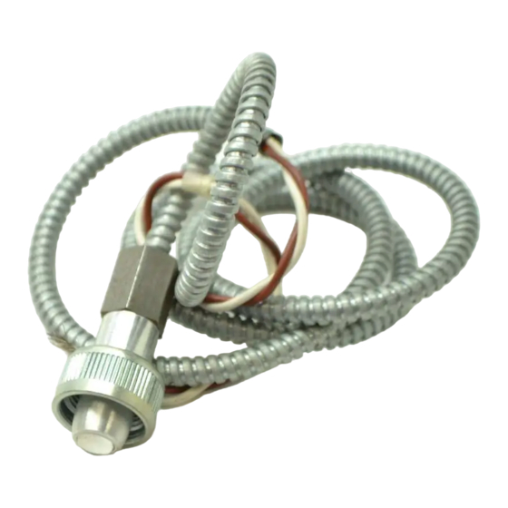
Infrared Flame Detector
The C7015A Flame Detector includes a lead
sulfide photocell that is sensitive to the infrared
radiation emitted by the combustion offuels such
as natural gas, oil, and coal.
n
applications.
q
When installed properly, can supervise the pilot
flame and/or the main burner flame.
Mounts easily on a standard 314 inch sight pipe.
n
The lead sulfide photocell plugs into an electrical
socket in the C?OlSA assembly and is field re-
placeable.
n
The lead sulfide photocell's sensitivity to infrared
F.P. * Rev. 11-91
radiation is compatible with a wide range of flame
supervisory applications.
48 and 96 inches [0.76, 1.22,2.64 m].
shields the detector leadwires.
q
Accessories available include a heat block, seal-off
adapter, reducer bushing, swivel mount and orifice
plate.
CONTENTS
l
Honeywell
Table of Contents

Related Manuals for Honeywell C7015A


Summary of Contents for Honeywell C7015A
-
Page 1: Application And Features 1
Infrared Flame Detector The C7015A Flame Detector includes a lead sulfide photocell that is sensitive to the infrared radiation emitted by the combustion offuels such as natural gas, oil, and coal. Particularily suitable for combination or dual-fuel applications. When installed properly, can supervise the pilot flame and/or the main burner flame. -
Page 2: Specifications
If you have additional questions, need further information, or would like to comment on our products or services, please write or phone: 1. Your local Honeywell Residential and Building Controls Division Sales Office (check white pages of phone directory). 2. Residential and Building Controls Division Customer Satisfaction Honeywell Inc., 1885 Douglas Drive North... -
Page 3: Dimension Drawings
C7015A leadwires are connected. The stickerprohibits routing any other wiring through the junction box. RRPLACFMENT PARTS: 104662D Lead Sulfide Photocells Fig. l-Mounting dimensions of C7015A infrared Flame Detector and accessories, in in. [mm]. 106061 HEAT BLOCK ‘COLLAR. 3/4 - 14 NPSM... -
Page 4: Operation
2. All wiring must be NBC Class 1 (line voltage). 3. Use the C7015A only with Honeywell lead sulfide photocells (part no. 104662D) and flame signal amplifiers specified, (see Table 6). -
Page 5: Table 2 -Diameter Of Area Sighted Through Various Lengths Of 3/4 Inch Pipe Without Orifice, In In
C7015A is mounted. FIELD OF VIEW A lead sulfide photocell, like other photocells, views an area rather than a point. It is unable to pinpoint pilot flame locationaseasilyasaflamerod.Ifthedetectoristoproveonly jlame, it must view only a part of... -
Page 6: Table 4 -Diameter Of Area Sighted Through Orifice, In In
C7015A INSTALLATION INSTALLING AN ORIFICE PLATE AnorificeplatewithahexagonalorificediameterofO.125 in. [3.2 mm] is available for the C7915A Infrared Flame Detector. The orifice can be mounted in front of the cell in the adapter seal-off or in a standard 314 in. coupling. (Refer to Fig. -
Page 7: Fig. 4 -C7015A Infrared Flame Detector Aimed At Side Wall Of Combustion Chamber
Refer to Figs. 2 and 3 for methods of reducing the ama of hot refractory sighted. Fig. 4--C7015A infrared Flame Detector aimed at side wall of combustion chamber. ‘, I __----- Fig. -
Page 8: Installing The Sight Pipe
SIGHT PIPE TEE MOUNTING THE DETECTOR PIPE Before mounting the C7015A , install the lead sulfide photocell (if not installed already). Unscrew the bushing from the cap, plu cell mount, and screw the bushing back into the cap (Fig. 8). The bushing also includes a focu&n g lens to concenuate available radiation on the photocell face. -
Page 9: Wiring
194°F [90” C] if used with a flame safeguard Honeywell specification no. R1298020 or equivalent for the FOCUSING LENS I F leadwire. (This wire is rated up to 400” F [204” Cl for continuous duty. It is tested for operation up to 600 volts and breakdown up to 7500 volts.) For the other leadwire, use... -
Page 10: Adjustments And Checkout
FLEXIBLE CABLE (MECHANICALLY SUPPORT TO MINIMIZE MOVEMENT) GROUNDlNG STRAP, 1 1 BROWN WIRE AND 1 WHITE WIRE FROM THE C7015A. CONNECT TO FLAME SAFEGUARD CONTROL’S SUBBASE, COLOR NOT IMPORTANT, KEEP WIRES AS SHORT AS POSSIBLE. AND TWIST THEM. AFLEXIBLE To FLAME SA... -
Page 11: Table 6-Flame Signal
RED CONNECTOR El 208 TABLE 6-FLAME SIGNAL Minimum Acceptable Steady Current (microamp) 2.25 ADJUSTMENTS AND CHECKOUT PROBES ECS 7700 CHASSIS MODULE FOOTMOUNT Maximum Minimum Expected Acceptable Steady Voltage Current (microamp) (Vb) 1.25 1.25 C7015A E2512A Maximum Expected Voltage (Vdc) 4.98 60-2306-5... - Page 12 C7015A ADJUSTMENTS AND CHECKOUT PILOT TURNDOWN TEST Ifthedetectorisusedtoproveapilotflamebeforethemain fuel valve( can be opened, perform a Pilot Turndown Test before welding the sight pipe into position. Follow the procedures in the instructions for the appropriate flame safeguard control, and the burner manufacturer instructions.
-
Page 13: Troubleshooting
Troubleshooting in the instructions for the appropri- ate flame safeguard control. EQUIPMENT REQUIRED 1. Voltmeter(HoneywellW136Aorequivalent)withOto 300 Vat scale. 2. Microammeter (Honeywell W136A or equivalent) with 0 to 25 microampdc range. 3. W136ACableConnector,partno. 196146, or 117053 Meter Connector Plug or equivalent (required for some meters). -
Page 14: Service
2. Open the master switch to disconnect power before removing or installing the detector. 3. If the C7015A is disassembled for any reason (e.g., to replace the lead sulfide cell or bushing with focusing lens), you must perform the Ad- justments and Checkout, page 11. -
Page 15: Table Of Contents
Table 6 -Flame Signal ... Figures Fig. 1 -Mounting dimensions of C7015A Infrared Flame Detector and accessories, in in. [mm]..3 Fig. 2 -Methods of reducing C7015A Infrared Flame Detector field-of-view ... 5 Fig. 3 -Using orifice plate to restrict detector field-of-view to intersection of pilot and main flame, or to small area of hot refractory ...