HP xw4600 Service And Technical Reference Manual
Workstation
Hide thumbs
Also See for xw4600:
- Technical reference manual (181 pages) ,
- Specification (73 pages) ,
- Quickspecs (68 pages)
Table of Contents
Quick Links
Table of Contents
Troubleshooting

Related Manuals for HP xw4600


Summary of Contents for HP xw4600
- Page 1 HP xw4600 Workstation Service and Technical Reference Guide...
- Page 2 Agency. warranties of merchantability and fitness for a particular purpose, and is subject to 453080-001 change without notice. The warranties for HP products are set forth in the express limited First Edition, September 2007 warranty statements accompanying such products.
-
Page 3: Table Of Contents
Installing or upgrading device drivers ..............16 Restoring the Windows Vista Business operating system ..........16 Using the HP Backup and Restore process ............16 Creating system recovery DVDs or CDs .......... 17 Restoring from HPBR DVDs or CDs ..........17 Restoring a system directly from the recovery partition .... - Page 4 Restoring the Linux operating system on preloaded workstations ....23 Creating restore media ..............23 Downloading the latest HP driver CD contents ........ 24 Reinstalling the factory Linux image with the HP driver CD ..... 24 Upgrading device drivers .................. 24 Linux-enabled workstations ....................24 Verifying hardware compatibility ...............
- Page 5 Asset tracking and security ....................40 Password security .................... 41 Establishing a setup password using the Computer Setup (F10) Utility ....................41 Establishing a power-on password using workstation setup .... 42 Entering a power-on password ............42 Entering a Setup Password .............. 43 Changing a power-on or setup password .........
- Page 6 Cable lock (optional) ......................62 Removing the cable lock ................... 63 Universal chassis clamp lock (optional) ................63 Removing the chassis clamp lock ..............63 Side access panel ......................64 Removing the side access panel ..............64 Replacing the side access panel ............... 65 Hood Sensor (Smart Cover Sensor) (optional) ..............
- Page 7 Product recycling ..........................108 5 System diagnostics and troubleshooting Customer Self Help .......................... 110 Help and Support Center ....................110 HP SoftPaq Download Manager ..................110 Diagnostic LED codes ..................... 110 Troubleshooting scenarios and solutions ................ 113 Solving minor problems ................... 113 Solving power supply problems ..............
- Page 8 Troubleshooting checklist ......................... 129 LED color definitions ........................129 HP Insight Diagnostics Offline Edition ....................131 Key features and benefits ....................131 Theory of operation ......................131 Diagnostic utility on CD ....................131 Downloading the latest diagnostic utility ................132 User Interface ........................
-
Page 9: Product Overview
Product overview This chapter presents an overview of the hardware components of the HP xw4600 Workstation, including the following topics: ● Product features on page 2 ● Workstation specifications on page 7 ● ENERGY STAR on page 13 ● Dual- and quad-core processors on page 14 ●... -
Page 10: Product Features
The following figure shows the HP xw4600 Workstation system board block diagram. Figure 1-1 System board block diagram Workstation components The following figure shows the components of a typical HP xw4600 Workstation. Drive configurations can vary. Chapter 1 Product overview ENWW... - Page 11 Figure 1-2 Workstation components view Table 1-1 Component view Item Description Item Description Power supply Processor Hard drive Memory module Optical drive System board Side access panel PCI Express card System fan...
-
Page 12: Front Panel Components
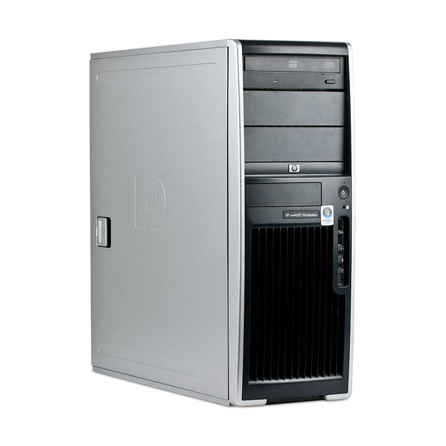
Front panel components The following figure shows the front panel components of a typical HP xw4600 Workstation. Drive configurations can vary. Figure 1-3 Front panel components Table 1-2 Front panel components Item Symbol Description Item Symbol Description Optical drive eject button... -
Page 13: Rear Panel Components
Rear panel components The following figure shows the rear panel components of a typical HP xw4600 Workstation. Figure 1-4 Rear panel components Table 1-3 Rear panel components Item Symbol Description Item Symbol Description Power supply Built-In Self Test (BIST) Padlock loop... -
Page 14: Serial Number And Coa Label Location
Serial number and COA label location Each workstation has two unique serial number labels (1) and a Certificate of Authentication (COA) label (2) (for Microsoft® Windows® preinstalled systems only). The serial number labels can usually be found on the top panel or on the side or rear of the workstation. Keep this number available when contacting customer service for assistance. -
Page 15: Workstation Specifications
16.8 cm (6.6 in.) wide 45.6 cm (17.9 in.) deep 80 Plus power supply The HP xw4600 Workstation includes a 475W energy efficient 80 Plus® power supply compatible with Energy Star requirements. This section describes the power supply and lists its specifications. Table 1-5... -
Page 16: Power Supply Specifications
WARNING! Do not exceed 110W of 5-V and 3.3-V power combination. Do not exceed 34.5A (414W) of 12V (CPU/B/D) power combination. Do not exceed 475W of total continuous output power. Power supply specifications Table 1-7 Power supply specifications Item Description Power supply 475 watt custom power supply –... -
Page 17: Power Supply Example Configuration 2
● One 160-GB SATA hard drive ● One optical drive ● One diskette drive ● One monitor, powered separately Table 1-8 Power supply example configuration 1 energy consumption 115 VAC 230 VAC 100 VAC Enabled Disabled Enabled Disabled Enabled Disabled Windows Idle (S0) 67.4W 66.4W... -
Page 18: Power Supply Example Configuration 3
● 2 optical drives ● 1 diskette drive Table 1-10 Power supply example configuration 2 energy consumption 115 VAC 230 VAC 100 VAC Enabled Disabled Enabled Disabled Enabled Disabled Windows Idle (S0) 113W 108W 113W WindowsBusy Typ (S0) 138W 133W 138W Windows Busy Max (S0) 186W... -
Page 19: System Fans
Table 1-12 Power supply Example configuration 3 energy consumption (continued) 115 VAC 230 VAC 100 VAC Idle (S0) ENERGY STAR Ptec (Total energy 162.3W 159.6W 163.2W consumption) Windows running Linpack and Viewperf ENERGY STAR 3.7W 4.1W 3.8W Sleep (S3)* ENERGY STAR 1.5W 1.8W 1.5W... -
Page 20: Resetting The Power Supply
Resetting the power supply If an overload triggers the power supply overload protection, all power is immediately disconnected. To reset the power supply: Disconnect the power cord from the workstation.. Determine what caused the overload and fix the problem. See System diagnostics and troubleshooting on page 109 for troubleshooting information. -
Page 21: Energy Star
ENERGY STAR HP computers marked with the ENERGY STAR logo are compliant with the applicable U.S. Environmental Protection Agency (EPA) ENERGY STAR specifications for computers. The EPA ENERGY STAR logo does not imply endorsement by the EPA. As an ENERGY STAR Partner, Hewlett- Packard Company has determined the products marked with the ENERGY STAR logo are ENERGY STAR qualified per the applicable ENERGY STAR guidelines for energy efficiency. -
Page 22: Dual- And Quad-Core Processors
Dual- and quad-core processors The HP xw4600 Workstation supports dual- and quad-core processors that provide two or four true processors in a single socket. Dual- and quad-core processors are better at handling the load of multi- threaded applications (such as rendering images in Digital Content Creation) and highly multi-tasked environments (such as running several productivity applications while listening to music). -
Page 23: Configuring And Restoring The Operating System
This section describes how to install and restore Microsoft Windows Vista® Business on your workstation. Configuring the Windows Vista Business operating system This section describes how to configure the Windows Vista Business operating system on your HP workstation. Configuring the software When you first power on the workstation, the operating system is configured. -
Page 24: Selecting A Language
After you have selected a language during the initial boot of the operating system, the language is locked on the hard drive. If the system is restored using HP Backup and Recovery, only the previously selected language can be installed. If using RestorePlus! DVDs, the RestorePlus! DVD looks for the language stored on the hard drive and restores only the original preinstalled language. -
Page 25: Creating System Recovery Dvds Or Cds
HP Recovery Partition is removed, the recovery partition is deleted, the user partition is extended to reclaim the unused hard drive space, and the F11 boot prompt is removed. The HP Backup and Recovery Manager application remains and can be used for data backup and restore. -
Page 26: Ordering Backup Software
Ordering backup software If you are unable to create system recovery CDs or DVDs, you can order a recovery disk set from the HP support center. Before calling HP to order the software, have your workstation serial number available. To obtain the support center telephone number for your region: Go to http://welcome.hp.com/country/us/en/wwcontact_us.html. -
Page 27: Configuring Windows Xp Professional
After you have selected a language during the initial boot of the operating system, the language is locked on the hard drive. If the system is restored using HP Backup and Recovery, only the previously selected language can be installed. If using RestorePlus! DVDs, the RestorePlus! DVD looks for the language stored on the hard drive and restores only the original preinstalled language. -
Page 28: Restoring The Windows Xp Professional Operating System
CDs for RestorePlus!, the Windows operating system, and a supplemental HP Backup and Recovery Manager. (There might be additional CDs you can create, depending on the options purchased.) You also have the option to move CD images to another location, such as a network share, to be copied to CD at a later time, or from another system. -
Page 29: Reclaiming Hard Drive Space From The Recovery Partition
The Windows operating system and device drivers (for devices included with the system) are reinstalled using the HP Backup and Restore (HPBR) process. This process can be executed from a DVD, CD, or from the recovery partition on your system hard drive. -
Page 30: Restoring From Hpbr Dvds Or Cds
For instructions on making backup copies of data files, see the operating system or backup utility documentation. HP software The following HP software might be installed on your workstation, depending on the operating system and options purchased: ●... -
Page 31: Setting Up Red Hat Linux
Creating restore media HP Red Hat Enterprise Linux includes a Red Hat ISO icon on the desktop. You can click on this icon to go to the /iso directory. The /iso directory contains all the iso images used to preload your workstation. -
Page 32: Downloading The Latest Hp Driver Cd Contents
Linux distribution. To install Linux, you must have the installation binary set for a Linux distribution (CD or DVD media, or a version on your network), and the HP Installer Kit for Linux. The HP Installer kit includes the HP CDs necessary to complete the installation of all versions of the distribution box set that are supported by HP workstation hardware. -
Page 33: Verifying Hardware Compatibility
Select your HP workstation model. Setting up Red Flag Linux Hewlett-Packard offers the Red Flag Linux operating system as a preloaded option on the HP xw4600 Workstation in certain countries, but HP does not support the Red Flag Linux operating system. For more information about Red Flag Linux and the Red Flag operating system software, see http://www.redflag-linux.com. - Page 34 Chapter 2 Configuring and restoring the operating system ENWW...
-
Page 35: System Management
System management This section describes the various tools and utilities that provide system management for your workstation and includes the following topics: ● Computer Setup (F10) Utility on page 27 ● Workstation management on page 35 Computer Setup (F10) Utility The Computer Setup (F10) Utility enables you to: ●... -
Page 36: Bios Rom
mode selected. To manually switch to POST Messages Enabled during POST, press any key except through F12. ● Establish an Ownership Tag, the text of which is displayed each time the system is powered on or restarted. ● Enter the Asset Tag or property identification number assigned by your company to this workstation. -
Page 37: Computer Setup (F10) Utility Menu
To access the Computer Setup (F10) Utility menu: Power on or restart the workstation. As soon as your display is active and F10=Setup appears in the lower right corner of the screen, press the key . NOTE: If you do not press at the appropriate time, try again. - Page 38 Table 3-1 Computer Setup (F10) Utility menu descriptions (continued) Heading Option Description Flash System CD-ROM—Enables you to upgrade the BIOS from a ROM image on a CD. USB—Enables you to upgrade the BIOS from a ROM image on a USB drive or memory stick. Replicated Save to Removable Media—Saves the system configuration, including CMOS, in the qsetup.txt Setup...
- Page 39 Table 3-1 Computer Setup (F10) Utility menu descriptions (continued) Heading Option Description SATA Emulation—Sets the SATA emulation mode with the following options: ● RAID–RAID OPROM executes. This emulation mode offers the best performance and most functionality. ● IDE–Offers standard SATA support (four ports only). ●...
- Page 40 Table 3-1 Computer Setup (F10) Utility menu descriptions (continued) Heading Option Description ● Serial port ● Parallel port ● Front USB port ● Rear USB port ● Internal USB port ● System audio ● Network controller ● Legacy diskette ● Embedded Security Device ●...
- Page 41 Table 3-1 Computer Setup (F10) Utility menu descriptions (continued) Heading Option Description Virtualization Technology Directed OS Management of Embedded Security Device—Enables or disables the ability of the operating system to control the TPM device, including turning it on and off, initializing it, and resetting it. Reset of Embedded Security Device through OS—Enables or disables the ability of the operating system to reset the TPM.
- Page 42 Table 3-1 Computer Setup (F10) Utility menu descriptions (continued) Heading Option Description finished). The POST delay also gives you more time to select F10 to enter the Computer Setup (F10) Utility. ● Limit (CPUID Maximum Value to 3) (Enable/Disable) Execute Tests workstation memory.
-
Page 43: Workstation Management
* Available on selected models. **These options should be used by advanced users only. Workstation management The HP Client Management Solutions (CMS) which are available for download from http://www.hp.com/ go/easydeploy are standards-based solutions for managing and controlling workstations in a networked environment. -
Page 44: Installing A Remote System
F12=Network Service Boot appears in the lower right corner of the HP logo screen. Follow the onscreen instructions to continue the installation process. The default boot order is a BIOS configuration setting that can be changed to always attempt a PXE boot. -
Page 45: Copying A Setup Configuration To Multiple Workstations
CAUTION: A setup configuration is model-specific. If source and target workstations are not the same model, file system corruption can result . For example, do not copy the setup configuration from an HP xw4200 Workstation to an HP xw4600 Workstation. -
Page 46: Altiris Client Management Solutions
Altiris Client Management Solutions Altiris and HP have partnered to provide comprehensive, tightly integrated systems management solutions to reduce the cost of owning HP client PCs. The HP Client Manager Software is the foundation for additional Altiris Client Management Solutions that address: ●... -
Page 47: Subscriber's Choice
Subscriber’s Choice and create a custom profile, see http://www.hp.com/subscriberschoice. ROM Flash Your HP workstation comes with a programmable flash ROM. By establishing a setup password in the Computer Setup (F10) Utility, you can protect the ROM from being inadvertently updated or overwritten. -
Page 48: Asset Tracking And Security
To recover the system after it enters Boot Block recovery mode: If there is media in the diskette or optical drives, remove it. Insert a BIOS image CD into the CD drive. USB media (such as an HP DriveKey) can also be used. Power off, then power on the workstation. -
Page 49: Password Security
Locally, using the Computer Setup (F10) Utility ● Remotely, using the HP Client Manager Software or System Software Manager which enables the secure, consistent deployment and control of security settings from a simple command line utility The following table and sections refer to the management of workstation security through the Computer... -
Page 50: Establishing A Power-On Password Using Workstation Setup
To establish a setup password using the Computer Setup (F10) menu: Power on or restart the workstation. As soon as the computer is powered on, press and hold the key until you enter the Computer Setup (F10) Utility. Press Enter to bypass the title screen, if necessary. -
Page 51: Entering A Setup Password
If you enter the password incorrectly, a broken key icon appears. Try again. After three unsuccessful tries, you must restart the workstation before you can continue. Entering a Setup Password If a setup password has been established on the workstation, you will be prompted to enter it each time you run the Computer Setup (F10) Utility. -
Page 52: Deleting A Power-On Or Setup Password
The power-on and setup passwords can also be changed using the Security options in the Computer Setup (F10) Utility. Deleting a power-on or setup password Power on or restart the workstation. To delete the power-on password, go to step 4. To delete the setup password, as soon as the workstation is powered on, press and hold the key until you enter the Computer Setup (F10) Utility. -
Page 53: Clearing Passwords
It is only available when hard drives that support the ATA security command set are detected. On HP workstations, it is not available when the SATA emulation mode is RAID+AHCI or RAID. DriveLock is intended for HP customers for whom data security is a paramount concern. For such customers, the cost of a hard drive and the loss of the data stored on it is inconsequential when compared to the damage that could result from unauthorized access to its contents. - Page 54 DriveLock. Since the initial configuration of DriveLock is typically performed by a system administrator, a master password should be set first. HP encourages system administrators to set a master password whether they plan to enable DriveLock or not. This gives the administrator the ability to modify DriveLock settings if the drive is locked in the future.
-
Page 55: Hood Sensor (Smart Cover Sensor) (Optional)
In a single drive workstation, if the drive has DriveLock enabled, the workstation might not be able to boot to the operating system, and might try to boot from the network or from another storage device instead (depending on the boot ordering options). Regardless of the outcome of the boot attempts, the drive-locked drive remains inaccessible without the DriveLock password. -
Page 56: Locking The Hood Lock
Forgotten password CAUTION: The side access panel FailSafe key is a specialized tool available from HP. Be sure to order the key from HP in advance so it is available when you need it. To obtain the FailSafe Key, contact HP post sales support by telephone at: 1-800–hp-invent, or by visiting http://welcome.hp.com/country/us/en/wwcontact_us.html. -
Page 57: Security Lock (Padlock Loop) (Optional)
If the workstation is connected to a network that is managed by HP Client Manager Software, the computer sends a fault notice to the network management application. With HP Client Manager Software, you can also remotely schedule diagnostics to automatically run on all managed PCs and create a summary report of failed tests. - Page 58 To change the power button configuration: Select Start, and then select Control Panel>Power Options. In Power Options Properties, select the Advanced tab. In the Power Button section, select Hibernate. (Hibernate must be enabled in the Hibernate tab.) After configuring the power button to function as a button, press the power button to put the system in a very low power state.
-
Page 59: Removal And Replacement Procedures
Removal and replacement procedures This chapter describes the removal and replacement procedures for most internal workstation components including the following topics: ● Warnings and cautions on page 52 ● Service considerations on page 53 ● Customer Self-Repair on page 58 ●... -
Page 60: Warnings And Cautions
Observe the following cautions when removing or replacing a processor: — Installing a processor incorrectly can damage the system board. Contact an HP authorized reseller or service provider to install the processor. If you plan to install the processor yourself, read all of the instructions carefully before you begin. -
Page 61: Service Considerations
— Create a common ground for the equipment you are working on by connecting the static-free mat, static strap, and peripheral units to that piece of equipment. NOTE: HP accessories are for use in HP Workstation products. They have been extensively tested for reliability and are manufactured to high quality standards. Service considerations The following sections describe service considerations that should be reviewed and practiced before removing and replacing any system components. -
Page 62: Preventing Esd Equipment Damage
Table 4-1 Static electricity (continued) Relative humidity Motions of bench worker 400V 800V 6,000V Removing bubble pack from PCB 7,000V 20,000V 26,500V Packing PCBs in foam-lined box 5,000V 11,000V 21,000V CAUTION: 700 volts can degrade a product. Preventing ESD equipment damage Many electronic components are sensitive to ESD. -
Page 63: Grounding The Work Area
Grounding the work area To prevent static damage in your work area: ● Cover the work surface with approved static-dissipative material. Use a wrist strap connected to the work surface, and properly grounded tools and equipment. ● Use static-dissipative mats, foot straps, or air ionizers to give added protection. ●... -
Page 64: Tools And Software Requirements
American National Standards Institute (ANSI) screws are used for hard drives. If an incorrect screw is used during the reassembly process, it can damage the workstation. HP strongly recommends that you keep all screws removed during disassembly with the removed part, and then returned to their proper locations. -
Page 65: Special Handling Of Components
Table 4-3 Screw ID Item Description Metric screws (M3) ANSI screws (6–32) Special handling of components The components included in this section require special handling when servicing the workstation. WARNING! Do not use the front bezel as a handle or lifting point when lifting or moving the workstation. Lifting the workstation from the front bezel, or lifting it incorrectly, could cause the workstation to fall, causing possible injury to you, and damage to the workstation. -
Page 66: Lithium Coin Cell Battery
Batteries, battery packs, and accumulators should not be disposed of with general household waste. Customer Self-Repair Customer Self-Repair enables you to obtain replacement parts and install them yourself on the workstation. For more information, see: http://www.hp.com/go/selfrepair/. Predisassembly procedures Perform the following steps before servicing the workstation: Close all open software applications. -
Page 67: System Board Components
System board components The following figure shows the system board connectors and sockets on the HP xw4600 Workstation. Figure 4-2 System board component identification Table 4-4 System board components Component Component Component Keyboard/mouse Clear CMOS button PCI Express x8 (4)*... -
Page 68: Removing And Replacing Components
Removing and replacing components This section provides procedures to remove and install hardware components on your workstation. Before servicing your workstation, review the safety information and precautions in the Service considerations on page 53, and the Safety and Regulatory Information for your workstation. Read all safety information and precautions. -
Page 69: Disassembly Order
Disassembly order Use the following table to determine the sequence in which to remove major workstation components. Table 4-5 Workstation component disassembly order Predisassembly (Predisassembly procedures on page Security lock (Security lock (Padlock loop) (optional) on page 62 Side access panel (Side access panel on page Hood Sensor... -
Page 70: Security Lock (Padlock Loop) (Optional)
Table 4-5 Workstation component disassembly order (continued) Hard drives (SAS hard drive on page 96), SATA hard drive on page Processor heatsink (Processor heatsink on page 103) Processor (System processor on page 105) System board (System board on page 107) Battery (Battery on page... -
Page 71: Removing The Cable Lock
Removing the cable lock To remove the cable lock, unlock it and pull it out of the cable lock slot as shown in the following figure. Figure 4-4 Removing the cable lock Universal chassis clamp lock (optional) If a universal chassis clamp lock is installed on your workstation, remove it before servicing the workstation. -
Page 72: Side Access Panel
Remove the screw attaching the lock to the chassis. Figure 4-6 Removing the lock screws Side access panel Before accessing the internal components of the workstation, the side access panel must be removed. This section describes how to remove and replace the side access panel. Removing the side access panel To remove the side access panel: WARNING! -
Page 73: Replacing The Side Access Panel
Pull open the access panel handle (1). Figure 4-7 Removing the access panel Slide the access panel toward the rear of the workstation and lift off the cover (2). Replacing the side access panel To replace the side access panel: Place the access panel over the chassis and align the tabs along the edges of the access panel with the slots in the chassis. -
Page 74: Removing The Hood Sensor
Removing the Smart Cover Lock solenoid To remove the Smart Cover Lock solenoid: NOTE: To purchase a FailSafe key, contact your authorized HP reseller or service provider, or visit the HP Web site for ordering information. Disconnect power from the system... -
Page 75: Front Bezel
Disconnect the solenoid cable from the system board (1). Figure 4-10 Removing the Smart Cover Lock solenoid assembly Using the FailSafe key (T-15 wrench), unscrew the two screws from the back of the chassis (2). Slide the solenoid assembly away from the chassis and out of the workstation (3). NOTE: To install the Smart Cover Lock solenoid assembly, reverse the previous steps. -
Page 76: Removing The Front Bezel
Removing the front bezel To remove the front bezel: Lift the two release snaps located on the front bezel (1). Figure 4-11 Removing the front bezel Rotate the front bezel away from the chassis to remove the bezel (2). Replacing the front bezel To replace the front bezel, align front bezel on the bottom and rotate in until it snaps into place. -
Page 77: Front Panel I/O Device Assembly
Gently push the subpanel out the back of the front bezel (1). Figure 4-12 Removing the bezel blanks Remove the desired bezel blank by applying outward pressure on the subpanel (1) and pulling the blank away (2). NOTE: The bezel blanks are keyed to assist you in replacing them. Also, the subpanel can be rotated 90 degrees to install optical drives in a desktop orientation. - Page 78 If necessary, unlatch the plastic snap that secures the cables inside the chassis (1), and then disconnect the front panel I/O device assembly cables from the system board (2). Figure 4-13 Removing front panel I/O device cables Remove the two smaller Torx screws (1) that hold the front panel I/O device assembly and bracket to the chassis (3).
-
Page 79: Installing The Front Panel I/O Device Assembly
Installing the front panel I/O device assembly To instal the front panel I/O device assembly: Thread each front panel I/O device assembly cable through the same holes from which they were removed. Push the front panel I/O device assembly into the chassis. Using your fingers, orient the cables so that there is enough room for the front panel I/O device assembly to easily fit in its slot. -
Page 80: System Speaker
Disconnect the power button assembly cable from the system board. Figure 4-16 Removing the power button assembly cable Press in on the clips that secure the power button assembly to the chassis (1). Figure 4-17 Removing the power button assembly Dislodge the metal clip from the chassis by rocking the power button assembly back and forth, and then slide the power button assembly out from the front of the chassis (2). -
Page 81: Removing The System Speaker
Removing the system speaker To remove the system speaker: Disconnect power from the system (Predisassembly procedures on page 58) and remove the side access panel (Removing the side access panel on page 64). Disconnect the speaker cable from the system board (1). Figure 4-18 Removing a system speaker Remove the four screws (2) securing the speaker to the chassis and remove the speaker from the... -
Page 82: System Fan Assembly
Remove the four screws from the back panel (1). Figure 4-19 Removing the power supply Slide the power supply toward the front of the chassis and lift it out of the chassis (2). NOTE: To replace the power supply, reverse the previous steps. System fan assembly This section describes how to remove the system fan assembly. -
Page 83: Memory
Disconnect the fan plug from the system board (1). Figure 4-20 Removing the system fan Use a cross-tip screwdriver to remove the four screws from the rear of the chassis (2). Lift the system fan out of the chassis (3). CAUTION: When replacing the system fan, be sure that the fan is seated with the airflow direction arrow pointing toward the rear of the chassis. -
Page 84: Installing A Memory Module
Dual-channel DIMMs Memory module requirements CAUTION: HP only ships DIMMs that are electrically and thermally compatible with this workstation. Because third-party DIMMs might not be electrically or thermally compatible, they are not supported by NOTE: DIMMs and their sockets are keyed for proper installation. Be sure these guides line up when installing DIMMs. -
Page 85: Required Dimm Installation Order
Required DIMM installation order Use the following illustration as a guide for installing memory: ● If installing only one DIMM, it must be installed in socket (1). ● The first DIMM pair must be installed in sockets (1) and (3). ●... - Page 86 Push gently outward on the socket levers. Figure 4-23 Opening the DIMM socket levers Align the DIMM connector key with the DIMM socket key, and then seat the DIMM firmly in the socket (1). Secure the socket levers (2). Figure 4-24 Installing a memory module Chapter 4 Removal and replacement procedures ENWW...
-
Page 87: Pci Card Slots
* The maximum graphics configuration can be: two 75W cards (one in slot two; one in slot four), or one 150W card, preferably in slot 2. If a 150W card is used, HP suggests that the adjacent slot remain empty. -
Page 88: Pci Card Support Bracket
PCI card support bracket Some PCI cards have retainers installed to prevent movement during shipping. Removing a PCI card support bracket To remove a PCI card support bracket: Disconnect power from the system (Predisassembly procedures on page 58) and remove the side access panel (Removing the side access panel on page Remove the two screws that attach the bracket to the chassis (1). -
Page 89: Pci Express Cards
PCI. The PCI Express I/O slots can support other PCI Express cards with less bus bandwidth than what is physically defined for the slot. Use the following table to determine PCI Express card compatibility. Table 4-7 PCI Express compatibility matrix for the HP xw4600 Workstation Slot type Mechanical compatibility Electrical compatibility... -
Page 90: Installing A Pci Express Card
Open the PCI card retention clamp. Press the retention clamp levers down to unsnap, and then rotate them up (1). Figure 4-28 Removing a PCI Express card If removing a PCI Express x16 graphics card, press in on the release lever (2) while lifting the card (3) out of the chassis. -
Page 91: Pci Card
Open the PCI card retention clamp. Press the retention clamp levers down to unsnap, and then rotate them up (1). Figure 4-29 Installing a PCI Express card Remove the PCI slot cover (2). Align the keyed components of the PCI card with the slot , and then firmly seat the card in the slot (3). -
Page 92: Installing A Pci Card
Open the PCI card retention clamp. Press the retention clamp levers down to unsnap, and then rotate them up (1). Figure 4-30 Removing a PCI card Lift the PCI card out of the chassis (2). Store the card in an anti static bag. Install a PCI slot cover and close the PCI retention clamp. -
Page 93: Ieee-1394 Card (Optional)
Open the PCI card retention clamp. Press the retention clamp levers down to unsnap, and then rotate them up (1). Figure 4-31 Installing a PCI card Remove the PCI slot cover (2). Align the keyed components of the PCI card with the slot , and then firmly seat the card in the slot (3). -
Page 94: Front Pci Card Guide And Fan Removal (Optional)
Open the PCI card retention clamp. Press the retention clamp levers down to unsnap, and then rotate them up (1). Figure 4-32 Removing an IEEE-1394 card Disconnect the front I/O cable and power cable from the card (2). Lift the IEEE-1394 card out of the chassis (3). Store the card in an anti static bag. Install a PCI slot cover and close the PCI card retention clamp. -
Page 95: Battery
Disconnect the fan wire from the connector on the system board and thread it out of the card guide (1). Figure 4-33 Removing the front fan housing/card guide Unsnap the fan housing/card guide from the chassis (2) and lift it out of the chassis (3). Remove the fan from the fan housing/card guide by applying outward pressure on the fan housing while pushing the fan out of the housing. -
Page 96: Removing The Battery
WARNING! This workstation includes a lithium battery. There is a risk of fire and chemical burn if the battery is handled improperly. Do not disassemble, crush, puncture, short external contacts, dispose in water or fire, or expose it to temperatures higher than 60°C (140°F). CAUTION: Before removing the battery, ensure that the CMOS settings are backed up in case they are lost when the battery is removed. -
Page 97: Power Connections To Drives
Power connections to drives For help identifying power cables, see the following figure. Ensure that all cables are routed or tied so that they cannot interfere with the processor heatsink fans. Figure 4-36 Identifying Identifying workstation power connectors for a typical configurationIdentifying Table 4-8 Workstation power connector description Item... -
Page 98: Optical Drive (Minitower Configuration)
Table 4-8 Workstation power connector description (continued) Item Description 1394 card Graphics card Optical drive (minitower configuration) This section describes how to remove and install an optical disk drive in a minitower workstation configuration. Removing an optical drive (minitower configuration) Disconnect power from the system (Predisassembly procedures on page 58), remove the side... -
Page 99: Installing An Optical Drive (Minitower Configuration)
Lift the green drive-lock release lever (1) and gently slide the drive out of the chassis (2). Figure 4-38 Removing the optical drive from the chassis After removing the optical drive (1), if you plan to install another drive, remove only the four guide screws from the drive casing (2). -
Page 100: Optical Drive (Desktop Configuration)
Insert the four black metric M3 guide screws into the drive casing (1). Figure 4-40 Installing the optical drive Align the screws with the grooves in the drive bay, and then gently slide the drive into the workstation until it snaps into place (2). CAUTION: Ensure that the optical drive is secure in the workstation chassis by pulling on the drive to see if it can become easily disengaged. - Page 101 Disconnect the data (1), power (2) cables from the drive. The connector colors might be different than shown in the following figure. Figure 4-41 Disconnecting the optical drive cables Press down on the yellow drive-lock release lever (1) and gently slide the drive out of the chassis (2).
-
Page 102: Installing An Optical Drive (Desktop Configuration)
After pulling the drive out (1), if you plan to install another drive, remove only the four guide screws from the drive (2). Figure 4-43 Removing the optical drive screws Installing an optical drive (desktop configuration) Disconnect power from the system (Predisassembly procedures on page 58), remove the side access panel... -
Page 103: Diskette Drive (Optional)
Diskette drive (optional) This section describes how to remove and install a diskette drive. Removing a diskette drive Disconnect power from the system (Predisassembly procedures on page 58), remove the side access panel (Removing the side access panel on page 64), and then remove the front bezel (Removing the front bezel on page 68). -
Page 104: Sas Hard Drive
SAS hard drive This section describes how to remove and install a SAS hard drive. Removing a SAS hard drive Disconnect power from the system (Predisassembly procedures on page 58), and then remove the side access panel (Removing the side access panel on page 64). -
Page 105: Installing A Sas Hard Drive
Remove the four guide screws from the hard drive and retain them for later use. Installing a SAS hard drive Disconnect power from the system (Predisassembly procedures on page 58), and then remove the side access panel (Removing the side access panel on page 64). - Page 106 Push the drive into the selected bay until it snaps into place (1). Figure 4-50 Installing the SAS hard drive Attach the power (2) and data (3) cables to the SAS drive. Insert the SAS controller card into an available PCI slot in the workstation chassis. Connect the data cable from the hard drive (1) to the controller card (2).
-
Page 107: Sata Hard Drive
SATA hard drive For more information about SATA hard drives and SATA RAID configurations, see Configuring RAID devices on page 141. This section describes how to remove and install a SATA hard drive. Removing a SATA hard drive To remove a SATA hard drive: Disconnect power from the system (Predisassembly procedures on page 58), and then remove... -
Page 108: Installing A Sata Hard Drive
Lift the green drive-lock release tab (1) and slide the hard drive out of the chassis (2). Figure 4-53 Removing the SATA hard drive Remove the four guide screws from the hard drive and retain them for later use. Installing a SATA hard drive To install one or two SATA hard drives: Disconnect power from the system (Predisassembly procedures on page... - Page 109 Attach the data (1) and power (2) cables to the SATA drive. Figure 4-54 Connecting the SATA cables to the SATA drive For a single SATA drive, connect the SATA 0 data cable from the hard drive (1) to the SATA0 port (2) in the workstation chassis.
-
Page 110: Installing Sata Hard Drives In The Optical Drive Bays (Optional)
Installing SATA hard drives in the optical drive bays (optional) If necessary, remove the EMI shield. Disconnect power from the system (Predisassembly procedures on page 58), remove the side access panel (Removing the side access panel on page 64), and then remove the front bezel (Removing the front bezel on page 68). -
Page 111: Processor Heatsink
Connect the data cable to the hard drive (1) and to the system board (2). Figure 4-58 Connecting the data cable Connect the power cable (not shown). Processor heatsink This section describes how to remove and install a processor heatsink. NOTE: Not all heatsinks are the same. - Page 112 Slowly and evenly loosen one pair of diagonally opposite screws (1) from the processor until the screw shanks disengage from the system board. Loosen the remaining pair (2). CAUTION: Do not fully loosen one screw, and then move on to the next. Loosen all screws a little at a time, ensuring that the processor remains level.
-
Page 113: Installing The Processor Heatsink
Installing the processor heatsink To install a heatsink: Disconnect power from the system (Predisassembly procedures on page 58), remove the side access panel (Removing the side access panel on page 64). and then remove the processor heatsink (Removing the processor heatsink on page 103). -
Page 114: Installing A System Processor
Raise the processor socket lever (1) and open the cover (2). Figure 4-61 Removing the system processor CAUTION: The processor socket contacts are delicate. To avoid bending the contacts, use extreme care when handling the processor. Pull the processor straight out of the socket (3). CAUTION: Do not touch the processor socket pins or the gold pads underneath the processor. -
Page 115: System Board
Align the triangle on the top of the processor with the triangle on the corner of the processor socket, and then install the processor into the socket. Ensure that the underside of the processor is level with the top of the processor socket. Close the socket cover and lightly press down on processor while closing the socket lever. -
Page 116: Installing The System Board
Product recycling The Planet Partners recycling service provides an easy way to recycle computer equipment, rechargeable batteries, or HP printing supplies. HP processes ensure that unwanted hardware or empty HP printing supplies are recycled responsibly. For information about recycling HP components or products, visit http://www.hp.com/go/recycle. -
Page 117: System Diagnostics And Troubleshooting
● Customer Self Help on page 110 ● Troubleshooting checklist on page 129 ● LED color definitions on page 129 ● HP Insight Diagnostics Offline Edition on page 131 ● POST error messages on page 135 ENWW... -
Page 118: Customer Self Help
Customer Self Help Help and Support Center The HP Help and Support Center (HSC) provides online access to technical support information, software updates and downloads, diagnostic tools, and HP support contact information. To open the online HSC from your desktop, select Start>Help and Support. - Page 119 Table 5-1 Diagnostic LED codes Chassis indicator LEDs Power LED and sound Diagnosis and service action activity None Workstation does not power on. Press the power button. If the hard drive LED is GREEN, then: Remove expansion cards one at a time. Replace the system board.
- Page 120 Reseat memory modules. pause, and then 5 beeps Replace memory modules one at a time to find the faulty module. Replace third-party modules with HP memory. Replace the system board. Blinks red 6 times (once per Pre-video graphic card error.
-
Page 121: Troubleshooting Scenarios And Solutions
Table 5-1 Diagnostic LED codes (continued) Chassis indicator LEDs Power LED and sound Diagnosis and service action activity Blinks red 8 times (once per Invalid ROM based on bad checksum. second), then a 2-second Reflash the ROM. pause, and then 8 beeps Replace the system board. -
Page 122: Solving Power Supply Problems
Table 5-2 Minor problems (continued) Problem Cause Possible Solution Workstation powered off Processor thermal protection Be sure workstation air vents are not blocked and the automatically and the Power activated. cooling fan is running. LED flashes red 2 times (once A fan might be blocked or not Open the access panel, press the power button, and every second), followed by a 2-... -
Page 123: Testing Power Supply
Testing power supply Before replacing the power supply, use the Built-In Self-Test (BIST) feature to learn if the power supply still works. To test the power supply: Unplug the AC power. Disconnect all internal power supply cables from the system board. Plug in AC power. -
Page 124: Solving Diskette Problems
Table 5-3 Power supply problems (continued) Problem Cause Solution Workstation powered off Processor thermal protection Be sure that the workstation air vents are not blocked automatically and the Power LED activated. and the cooling fan is running. flashes red 2 times (once every A fan might be blocked or not Open the access panel, press the power button, and second), followed by a 2-second... -
Page 125: Solving Hard Drive Problems
Table 5-4 Diskette problems (continued) Problem Cause Solution Diskette is write-protected. Use another diskette or remove the write protection. Writing to the wrong drive. Verify the drive letter in the path statement. Not enough space is left on the Use another diskette. diskette. -
Page 126: Solving Display Problems
Table 5-5 Hard drive problems (continued) Problem Cause Solution Disk transaction problem. The directory structure is bad, Right-click Start, select Explore, and select a drive. or there is a problem with a file. Select File>Properties>Tools. Under Error-checking, select Check Now. Drive not found (identified). - Page 127 Table 5-6 Display problems (continued) Problem Cause Solution Screen blanking utility installed Press any key or press the mouse button, and, if set, enter or energy saver features your password. enabled. System ROM is bad; system is Reflash the ROM using a SoftPaq. running in FailSafe Boot Block mode (indicated by 8 beeps).
-
Page 128: Solving Audio Problems
Table 5-6 Display problems (continued) Problem Cause Solution The picture is broken up, rolls, The monitor connections might Be sure the monitor cable is securely connected to the jitters, or flashes. be incomplete, or the monitor workstation. might be incorrectly adjusted. In a two-monitor system, or if another monitor is in close proximity, ensure that the monitors are not interfering with each other’s electromagnetic field by... -
Page 129: Solving Printer Problems
Table 5-7 Audio problems (continued) Problem Cause Solution Right-click the CD/DVD device and select Properties. On the Properties tab, ensure that Enable digital CD audio for this CD-ROM device is selected. Headphones or devices Turn on and use headphones or external speakers, if connected to the line-out connected, or disconnect headphones or external connector have muted the... -
Page 130: Solving Keyboard And Mouse Problems
Table 5-8 Printer problems (continued) Problem Cause Solution If you are on a network, you Make the proper network connection to the printer. might not have made a connection to the printer. Printer might have failed. Run printer self-test. Printer does not turn on. The cables might not be Reconnect all cables. -
Page 131: Solving Front Panel Component Problems
The port is not there because it You can buy an IEEE 1394 PCI adapter card. Contact an was not purchased with the HP seller. system. Solving hardware installation problems You might need to reconfigure the workstation when you add or remove hardware, such as an additional diskette drive. - Page 132 Replace DIMMs one at a time to isolate the faulty 2–second pause, and then the module. workstation beeps 5 times. Replace third-party memory with HP memory. Replace the system board. Power LED flashes red 6 times Video card is not seated...
-
Page 133: Solving Network Problems
Solving network problems The following table provides fixes for common network problems. Table 5-12 Network problems Problem Cause Solution Wake-on-LAN feature is not Wake-on-LAN is not enabled. Use the network control application to enable Wake-on- functioning. LAN. Network driver does not detect Network controller is disabled. -
Page 134: Solving Memory Problems
Flash the ROM. reports unprogrammed EEPROM. Solving memory problems CAUTION: For those systems that support ECC memory, HP does not support mixing ECC and nonECC memory. The operating system does not boot with mixed-ECC memory. Table 5-13 Memory problems Problem... -
Page 135: Solving Processor Problems
Table 5-13 Memory problems (continued) Problem Cause Solution Replace third-party memory with HP memory. Replace the system board. Solving processor problems Table 5-14 Processor problems Problem Cause Solution Poor performance is experienced. Processor is hot. Be sure the airflow to the workstation is not blocked. -
Page 136: Solving Internet Access Problems
Table 5-15 DVD problems (continued) Problem Cause Solution Windows does not detect the Use Device Manager to remove or uninstall the DVD-ROM drive. device. Restart the workstation and allow Windows to detect the device. Recording audio CDs is difficult or Wrong or poor-quality media Use a slower recording speed. -
Page 137: Troubleshooting Checklist
Table 5-16 Internet access problems (continued) Problem Cause Solution Double-click Ports (COM & LPT). Right-click the COM port that your modem uses, and then select Properties. Under Device status, verify that the modem is working properly. Under Device usage, verify that the modem is enabled. - Page 138 Table 5-17 LED color definitions (continued) LED state LED color System status Flashing Green System is in Standby Solid or flashing System has experienced an error. See Diagnostic LED codes on page 110 None No light System is in Hibernate, or it is off 130 Chapter 5 System diagnostics and troubleshooting ENWW...
-
Page 139: Hp Insight Diagnostics Offline Edition
You can select tests that do not require any user interaction through the Interactive and Unattended tests modes. Diagnostic utility on CD HP Insight Diagnostics is available on the Documentation Library CD included with your workstation. ENWW HP Insight Diagnostics Offline Edition 131... -
Page 140: Downloading The Latest Diagnostic Utility
Go to http://www.hp.com. Select the Support & Drivers link. Select the Download driver and software radio button. Enter your product number (for example, xw4600) in the text box, and then press Enter. Select your operating system. Select the Diagnostic link. -
Page 141: Test Tab
If you want to run the diagnostic test for a specified time period, enter the amount of time in minutes. To start the test, select Begin Testing in the lower right corner of the display. ENWW HP Insight Diagnostics Offline Edition 133... -
Page 142: Status Tab
While tests are performed, you can monitor the progress by viewing the Status tab. Any errors that are detected are summarized in the Error Log. Select Save to save the report to a diskette or a USB key drive (if attached). If the diagnostics utility detects an error during a test, the user can mouse over the failed text in the Status tab to display additional information about the type of error and the error code. -
Page 143: Help Tab
Help tab The Help tab provides three views: ● HP Insight Diagnostics—Provides introductory and detailed information about Insight Field Diagnostics. ● Error Codes—Provides error code listings, including devices tested, messages, and recommended repair information. ● Test Components—Reloads and refreshes all components and displays component details after the refresh. - Page 144 Run the Computer Setup (F10) Utility or Windows utilities. Verify that the memory modules (if any) are installed properly. If third-party memory has been added, test using HP memory only. Verify proper memory module type. 201—Memory Error RAM failure. Run the Computer Setup (F10) utiltiy or Windows utilities.
- Page 145 Table 5-18 POST error messages (continued) Screen message Probable cause Recommended action 216—Memory Size Exceeds The amount of memory installed Verify how much memory your system supports. Maximum Supported exceeds that supported by the Remove the excess memory. hardware. 219—ECC Memory Module ECC modules not supported on this Remove the ECC module.
- Page 146 Run the Drive Protection System test (if applicable). Apply firmware patch (if applicable). See http://www.hp.com/support. Back up contents and replace the hard drive. 1780—Disk 0 Failure The drive is not installed correctly or Be sure that any jumpers are set correctly, and has failed.
- Page 147 Table 5-18 POST error messages (continued) Screen message Probable cause Recommended action 1781—Disk 1 Failure The drive is not installed correctly or Be sure that any jumpers are set correctly and that has failed. power and drive cables are connected, both to the drive and the system board.
- Page 148 Run the Computer Setup (F10) Utility. Number If the setup utility already has data in the field, or it will not allow the serial number to be entered, see http://www.hp.com. Download and run the sp5572.exe (snzero.exe) utility. Run the Computer Setup (F10) Utility again and try to enter the serial number under Security>System ID.
-
Page 149: Configuring Raid Devices
Configuring SAS RAID devices Supported configurations The following RAID configurations are supported on the HP xw4600 Workstation. NOTE: This section does not apply to configuring RAID in the Linux environment. For RAID in the Linux environment, configure RAID configurations as provided by Red Hat Enterprise Linux. -
Page 150: Sas Raid 0 Configuration
◦ Can recover from single drive failure ◦ Improved read performance ● RAID 1E ◦ Three drives minimum ◦ Can be an odd number of drives ◦ Can always recover from a single drive failure and, in some cases, can recover from two drive failures SAS RAID 0 configuration Follow the steps below to configure an Integrated Striped (IS) volume with the BIOS-based configuration... -
Page 151: Sas Raid 1E Configuration
To configure a two-disk mirrored volume with an optional hot spare disk: ● In the RAID Properties screen, use the arrow keys to select the primary disk for the IM volume (the disk with the data you want to mirror.) ●... -
Page 152: Configuring Sata Raid Devices
(Optional) Use the arrow keys to select a hot spare disk for the IME volume. Select Yes as the value for the Hot Spare column. When you have selected all disks for the IME volume, press Esc and select Save changes, then exit this menu. -
Page 153: Creating Raid Volumes
Press F10 to accept the new setting. Use the arrow keys to highlight Advanced>Device Options, and press Enter. Use the up or down arrow key to highlight SATA RAID Option ROM Download, and press Enter. Use the left or right arrow key to select Enable. Press F10 to accept the new setting. - Page 154 When prompted, press Y to confirm the deletion of the selected RAID volume. Choose one of the following steps: ● Return to step 1 to delete additional RAID volumes. ● To create RAID volumes, see Creating RAID volumes on page 145.
-
Page 155: Configuring Password Security And Resetting Cmos
Configuring password security and resetting CMOS This chapter describes how to configure password security and to reset CMOS, and includes these topics: ● Preparing to configure passwords on page 148 ● Resetting the password jumper on page 149 ● Resetting the password jumper on page 149 ENWW... -
Page 156: Preparing To Configure Passwords
Preparing to configure passwords The Computer Setup (F10) Utility enables you to create setup and power-on passwords. When you create a setup password, only the power-on password is required to access the Computer Setup (F10) Utility and any other information on the workstation. When you create both passwords, only the setup password gives you access to the Computer Setup (F10) Utility. -
Page 157: Resetting The Password Jumper
Resetting the password jumper To disable the power-on or setup password features and clear the power-on and setup passwords: WARNING! To reduce the risk of personal injury from electrical shock and hot surfaces, be sure to disconnect the power cord from the wall outlet and allow the internal system components to cool before touching. -
Page 158: Clearing And Resetting The Cmos
Clearing and Resetting the CMOS The CMOS of the workstation stores password information and information about the workstation configuration. This section describes the steps necessary to successfully clear and reset the CMOS. Using the CMOS Button Follow the steps below to clear CMOS using the Clear CMOS button: WARNING! To reduce the risk of personal injury from electrical shock and hot surfaces, be sure to disconnect the power cord from the wall outlet and allow the internal system components to cool before... -
Page 159: Using The Computer Setup (F10) Utility To Reset Cmos
Using the Computer Setup (F10) Utility to Reset CMOS Access the Computer Setup (F10) Utility menu. When the Computer Setup message appears in the lower-right corner of the screen, press F10. Press Enter to bypass the title screen, if necessary. NOTE: If you do not press the key while the message is displayed, the workstation must be... - Page 160 152 Chapter 7 Configuring password security and resetting CMOS ENWW...
-
Page 161: Appendix A Appendix A-Connector Pins
Appendix A—Connector pins Connector pin descriptions Workstation Signal Workstation keyboard connector Data Unused Ground +5 VDC Clock Unused Workstation mouse connector Signal Data Unused Ground +5 VDC Clock Unused ENWW Connector pin descriptions 153... - Page 162 Workstation Ethernet connector 10/100–MbSignal 1000–Mb signal (+) Transmit Data TX/RX (-) Transmit Data TX/RX – (+) Receive Data TX/RX Unused TX/RX RX/RX – Unused TX/RX – (-) Receive Data TX/RX Unused TX/RX – Unused Workstation parallel connector Signal Signal Signal Strobe Data Bit 5 Select...
- Page 163 Workstation USB connector Signal +5 VDC - Data + Data Ground Workstation IEEE 1394 connector Signal Power TPB- TPB+ TPA- TPA+ Microphone cable connector (1/8 inch) Signal 1 (Tip) Audio 2 (Ring) Power 3 (Shield) Ground Headphone cable connector (1/8 inch) Signal 1 (Tip) Audio_Left...
- Page 164 Line-out audio cable connector (1/8 inch) Signal 3 (Shield) Ground SATA drive connector Signal Signal Signal Data Cable Power Cable Power Cable Ground 3.3V power 5V power 3.3V power 5V power 3.3V power Ground Ground Ground Reserved S5** Ground Ground S6** Ground 12V power...
- Page 165 SAS drive connector Segment Backplane Plug and receptacle cable receptacles Secondary signal segment SIGNAL GROUND SIGNAL GROUND SIGNAL GROUND Power segment precharge GROUND GROUND GROUND precharge GROUND READY LED GROUND precharge ENWW Connector pin descriptions 157...
- Page 166 Workstation VGA connector Signal Signal Signal Red Analog Monitor ID Green Analog DDC Serial Data Blue Analog Horizontal Sync Monitor ID +5 VDC Vertical Sync DDC Serial Clock DVI-I cable connector Signal Signal T.M.D.S DATA 2- HOT PLUG DETECT T.M.D.S DATA 2+ T.M.D.S DATA 0- T.M.D.S DATA 2/4 SHIELD T.M.D.S DATA 0+...
- Page 167 24-pin main power cable connector +3.3V +3.3V +3.3V -12V +5 Vaux +12 V-B PS_ON_L +12 V-B Unused Unused 4-pin power (CPU/memory/aux. sys. Color Signal board) cable connector +12 VCPU +12 VCPU 6-pin power (auxiliary PCI Express) Color Signal cable connector +12 V-D +12 V-D +12 V-D...
- Page 168 6-pin power (auxiliary PCI Express) Color Signal cable connector NOTE: The 6-pin power (auxiliary PCI Express) is only required with high- powered graphics cards. Workstation AUX_IN connector Signal AUX_LEFT AGND AGND AUX_RIGHT Internal USB system board 2x5 Signal connector USB6# USB7# CAUTION: Possible equipment damage.
- Page 169 Workstation processor, PCI, and rear Signal chassis fan connector Ground +12V Tach Workstation FDD connector Signal Signal Ground FLP_DIR# FLP_LOWDEN# Ground Tach FLP_STEP# FLP_WDO Ground FLP_STEP# Unused Ground Ground FLP_WRTEN# FLP_INDEX# Ground Ground FLP_TRACK# FLP_MOTOR# Ground Ground FLP_WP# Unused Ground Ground FLP_RD_D# FLP_SEL_A#...
- Page 170 Workstation Signal Signal internal serial connector DTR2# RXD2 +3.3V AUX CTS2# RTS2# DSR2# +3.3V TXD2 DCD2# +3.3V AUX -12V Ground +12V Ground 162 Appendix A Appendix A—Connector pins ENWW...
- Page 171 Appendix B—System board designators This appendix lists the system board designators for this system. Designator Silkscreen Component MTG1-MTG10 Mounting holes Boot block header/jumper Clear password header/jumper SLOT 5 PCI PCI slot SLOT 6 PCI PCI slot Slot 7 PCI PCI slot SLOT 3 PCIe x8 (4) PCI Express slot SLOT1 PCIe x1...
-
Page 172: Appendix B Appendix B-System Board Designators
Designator Silkscreen Component FRNT AUDIO Front panel audio header FRNT USB Front panel USB header INT USB Internal USB header U1037 U1037 Internal Type A USB HDD LED connector CONTROL PANEL Main power/HDD LED/internal speaker connector CPU FAN Primary processor fan header SYS FAN Chassis fan header PCI FAN... -
Page 173: Appendix C Appendix C-Routine Care
Appendix C—Routine care General cleaning safety precautions ● Never use solvents or flammable solutions to clean the workstation. ● Never immerse any component in water or cleaning solutions; apply any liquids to a clean cloth and then use the cloth on the component. ●... -
Page 174: Cleaning The Workstation Case
Cleaning the workstation case ● Follow the service consideration (Service considerations on page 53) presented before cleaning the workstation. ● To remove light stains or dirt, use plain water with a clean, lint-free cloth or swab. ● For stronger stains, use a mild dish washing liquid diluted with water. Rinse well by wiping it with a cloth or swab dampened with clear water. -
Page 175: Cleaning The Mouse
Cleaning the mouse Follow the safety precautions presented in Service considerations on page 53 before cleaning the mouse. Remove the mouse ball from the housing by removing the retaining plate. Clean the mouse ball. Pull out any debris from the ball socket, and wipe the ball with a clean, dry cloth. Reassemble the mouse. - Page 176 168 Appendix C Appendix C—Routine care ENWW...