Table of Contents
Quick Links
Chapters
Table of Contents

Related Manuals for Acer A100


Summary of Contents for Acer A100
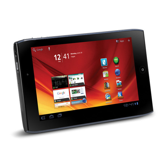
- Page 1 ICONIA Tab A100/A101 SERVICE GUIDE...
-
Page 2: Revision History
Copyright Copyright © 2011 by Acer Incorporated. All rights reserved. No part of this publication may be reproduced, transmitted, transcribed, stored in a retrieval system, or translated into any language or computer language, in any form or by any means, electronic, mechanical, magnetic, optical, chemical, manual or otherwise, without the prior written permission of Acer Incorporated. -
Page 3: A100
Conventions The following conventions are used in this manual: WARNING: Indicates a potential for personal injury. CAUTION: Indicates a potential loss of data or damage to equipment. IMPORTANT: Indicates information that is important to know for the proper completion of a procedure, choice of an option, or completing a task. -
Page 4: General Information
Acer-authorized Service Providers: Your Acer office may have a different part number code than those given in the FRU list in this service guide. The list provided by your regional Acer office must be used to order FRU parts... -
Page 5: Table Of Contents
CHAPTER 1 Hardware Specifications Features ..........1-5 Form Factor. - Page 6 Audio Codec and Amplifier ......1-24 Audio Interface........1-25 Wireless Module 802.11b/g/n .
- Page 7 IO Board Removal........3-29 IO Board Installation ....... 3-30 Microphone Module Removal .
- Page 8 A100/A101........
- Page 9 CHAPTER Hardware Specifications...
- Page 10 Features ..........1-5 Form Factor.
- Page 11 AC Adapter ........1-26 System Power Management .
-
Page 13: Features
Hardware Specifications and Configurations Features The following is a summary of the computer’s many features: Form Factor 7" Tablet Tegra 250 Dual cortex A9, 1GHz ® GPU Ultra Low Power GeForce Memory RAM: LP DDR2 up to 1GB, POP type, discrete on board ... -
Page 14: Camera
Camera Rear camera: 5M Camera with Auto focus (Chicony / Aptina 5140) with flash lights (single LED) Detail spec Focus speed < 0.7 sec at 5 lux with flash lights (single LED) Min exposure time: 1/15 sec ... -
Page 15: Audio
Audio Single analog Microphone (Noise / echo cancellation) Dual Speaker: above 1.0W/pcs, chamber size is 1cc around each 3.5mm Audio Jack 4ring (with Mic) Dolby Operation System Gingerbread Dimension and Weight Dimensions 195 (L) x 117 (W) x 13.1 (H) mm Weight ... -
Page 16: Others
Others Reset hole Docking support (HDMI, power, audio) Accessories In Box Charger + Plug Optional Earphone Micro SD Card Docking + IR remote Pouch Hardware Specifications and Configurations... -
Page 17: Notebook Tour
Notebook Tour Front View Figure 1-1. Front View Table 1-1. Front View Icon Item Description Front Camera 2M Pixel CCD Light Sensor Touch Window Home Button Hardware Specifications and Configurations... -
Page 18: Rear View
Rear View Figure 1-2. Front View Table 1-2. Front View Icon Item Description Rear Camera 5M Pixel CCD LED Flash 1-10 Hardware Specifications and Configurations... -
Page 19: Top View
Top View Figure 1-3. Top View Table 1-3. Top View Icon Item Description Rotation Lock switch Screen Rotation Control Lock switch Volume Control Key Card Slots SIM*/microSD card slot (* only for A101) 1-11 Hardware Specifications and Configurations... -
Page 20: Left View
Left View Figure 1-4. Left View Table 1-4. Left View Icon Item Description Headphones/ Speaker Jack Power/ Resume Power on machine or resume from sleep mode. Button Microphone 1-12 Hardware Specifications and Configurations... -
Page 21: Right View
Right View Figure 1-5. Right View Table 1-5. Right View Icon Item Description Reset Button micro-HDMI Port Micro (Type D) HDMI port. Docking Port micro-USB Connector DC-IN Jack Speakers 1-13 Hardware Specifications and Configurations... - Page 22 Bottom View (N/A) Figure 1-6. Bottom View Table 1-6. Bottom View Icon Item Description 1-14 Hardware Specifications and Configurations...
-
Page 23: System Block Diagram
System Block Diagram Figure 1-7. System Block Diagram 1-15 Hardware Specifications and Configurations... -
Page 24: Specification Tables
Specification Tables Computer specifications Item Metric Imperial Dimensions Length 195.0 mm 7.68 inch Width 117 mm 4.61 in Height 13.1mm 0.52in (front to rear) Weight (equipped with optical ~405 g 0.9 lbs drive, flash drive, and battery) Weight (equipped with optical Build-in battery Build-in battery drive, flash drive, and battery) -
Page 25: System Board Major Chips
System Board Major Chips Item Specification Core logic Tegra 250 Dual cortex A9, 1GHz Integrated with CPU USB 2.0 Controller integrated with CPU Super I/O controller Integrated with CPU Bluetooth Broadcom BCM4329 Wireless Broadcom BCM4329 PCMCIA Audio codec Wolfson WM8903 Card reader SD card controller integrated with CPU LVDS transmitter... -
Page 26: Processor Specifications
Processor Specifications Item CPU Speed Cores/ Cache Package Voltage (GHz) Threads Speed Tech Size (FSB/ (nm) DMI/QBI) 1 GHz 2 Cores 64 bits 40 nm 1 MB 23x23 1.0-1.2V FCBGA CPU Fan True Value Table (N/A) CPU Temperature Fan Speed (RPM) SPL Spec (dBA) System Memory Item... -
Page 27: Video Interface (Integrated)
Memory Combinations (N/A) Slot 1 (MB) Slot 2 (MB) Total Memory (MB) Video Interface (Integrated) Item Specification Chipset Package Interface Compatibility Sampling rate 1-19 Hardware Specifications and Configurations... -
Page 28: Lan Interface
BIOS (N/A) Item Specification BIOS vendor BIOS Version BIOS ROM type BIOS ROM size Features LAN Interface Item Specification LAN Chipset N/A (No LAN Port) LAN connector type N/A (No LAN Port) LAN connector location N/A (No LAN Port) Features UMTS /WCDMA a. - Page 29 Hard Disk Drive (AVL components) (N/A) Item Specification Vendor & Model Name Capacity (GB) Bytes per sector Data heads Drive Format Disks Spindle speed (RPM) Performance Specifications Buffer size Interface Fast data transfer rate (Mbits / sec, max) Media data transfer rate (Mbytes/sec max) DC Power Requirements...
-
Page 30: Led 7.1
BD Drive (N/A) Items Specifications Vendor & Model name Performance Specification Transfer rate (KB/sec) Buffer Memory Interface Applicable disc format Loading mechanism Power Requirement Input Voltage LED 7.1” Item Specification Vendor/Model name CMI/AT070TNA2 Screen Diagonal (mm) 255.52 mm Active Area (mm) 222.72 mm x 125.28 mm Display resolution (pixels) 1024 x 3(RGB) x 600... -
Page 31: Display Supported Resolution (Lcd)
LCD Inverter (N/A) Item Specification Vendor & Model name Brightness conditions Input voltage (v) Input current (mA) Output voltage (V, RMS) Output current (mA, RMS) Output voltage frequency (KHz) Display Supported Resolution (LCD) Resolution 16 bits 32 bits Intel NVIDIA 1024x 3(RGB) x 600 Graphics Controller (N/A) Item... -
Page 32: Bluetooth Module
Bluetooth Module Item Specifications Controller Azurewave AW-NH611 - Broadcom BCM4329 SoC Features Fully support BT 2.1 +EDR UART Interface Camera Item Specification Vendor and Model Chicony CJAA525 Type Mini Card Item Specification Number supported Features 1 mini card slot (for WWAN module) 3G Card Item Specification... -
Page 33: Audio Interface
Audio Interface Item Specification Audio Controller Wolfson WM8903 Audio onboard or optional On board Mono or Stereo Stereo Resolution Support 24bit Compatibility I2S audio Interface Sampling rate Sample rate up to 44.1KHz Internal microphone Internal speaker/quantity Yes/(1W speakers x2) Wireless Module 802.11b/g/n Item Specification Chipset... -
Page 34: Usb Port
USB Port Item Specification USB compliance level USB2.0 Protocol EHCI Number of USB port(s) Location one at the right side Output Current HDMI Port Item Specification Compliance level HDMI1.3a Data throughput Up to 16.7 million colors Number of HDMI port(s) Location one at the right side AC Adapter... -
Page 35: Card Reader
Card Reader Item Specification Chipset Embedded in T20 SOC. Package FCBGA -664 23X23 Maximum supported size SD: 32G Features Storage cards with adapter: mirco SD™ System LED Indicator Item Specification Lock System state White color : Flash on booting White color and amber color off : System off / suspend ... -
Page 36: System Interrupt Specification (N/A)
System Interrupt Specification (N/A) Hardware IRQ System Function IRQ0 IRQ1 IRQ2 IRQ3 IRQ5* IRQ6 IRQ7* IRQ8 IRQ9* IRQ10* IRQ11 IRQ12 IRQ13 IRQ14 IRQ15 *Default configuration; audio possible configurations are IRQ5, IRQ7, IRQ9, IRQ10, or none. NOTE: ExpressCards may assert IRQ3, IRQ4, IRQ5, IRQ7, IRQ9, IRQ10, IRQ11, or IRQ15. Either the infrared or the serial port may assert IRQ3 or IRQ4 1-28 Hardware Specifications and Configurations... -
Page 37: System Io Address Map
System IO Address Map I/O address (hex) System function (shipping configuration) 000 - 00F DMA controller no. 1 010 - 01F Unused 020 - 021 Interrupt controller no. 1 022 - 024 Opti chipset configuration registers 025 - 03F Unused 02E - 02F 87334 "Super I/O"... -
Page 38: System I/O Address Specifications
System I/O Address Specifications I/O address (hex) System function (shipping configuration) 220 - 22F Entertainment audio 230 - 26D Unused 26E - 26 Unused 278 - 27F Unused 280 - 2AB Unused 2A0 - 2A7 Unused 2A8 - 2E7 Unused 2E8 - 2EF Reserved serial port 2F0 - 2F7... -
Page 39: Diagnostic Utilities
CHAPTER Diagnostic Utilities... -
Page 40: Introduction
Introduction ......... 2-3 Diagnostic Tools . -
Page 41: Introduction
Diagnostic Utilities Introduction The ICONIA Tab A100/A101 has a set of software tools designed to diagnose problems with its hardware components. Diagnostic Tools To access the diagnostic tools utility guide, click here. NGA EUU Installation Procedure NOTE: NOTE: Before installing EEU software, make sure ICONIA tablet is not connected to a computer. - Page 42 3. Install USB driver. (Figure 2-3) Figure 2-3. USB Driver Installation 4. To enable USB debugging, on the device, go to the Settings/Applications/Development menu and click the USB debugging checkbox. (Figure 2-4.) Figure 2-4. USB Debugging Diagnostic Utilities...
- Page 43 5. Follow the instructions shown in Figure 2-5 to find OS image version. Figure 2-5. Finding OS Image Version 6. If image version is not available, follow instructions in Figure 2-6 to manually reset device. When procedure is complete, go to Step 1 of this procedure.
- Page 44 7. If image version is available, current and new version information is shown. Click Next to continue. (Figure 2-7) Figure 2-7. Image Versions 8. Enter CPU ID of device. Click Next to continue. (Figure 2-8) NOTE: NOTE: Maximum number of characters for ID is sixteen (16). Figure 2-8.
- Page 45 9. Upgrade process begins as shown in Figure 2-9 IMPORTANT: Upgrade process will not complete if USB cable is unplugged. Figure 2-9. Upgrade Process 10. If upgrade process is successful, Figure 2-10 is shown. If an upgrade error is shown, go to step 12, If a CPU ID value error is identified, go to step 19.
- Page 46 12. If CPU ID is correct but upgrade process is not successful, Figure 2-11 is shown. Figure 2-11. Upgrade Process Failure 13. Click Retry to start upgrade process. Go to Step 14. Click Exit to cancel upgrade process. 15. If upgrade process is cancelled, a confirmation dialog is shown. (Figure 2-12) Figure 2-12.
- Page 47 18. Click OK to exit the program. (Figure 2-13) Figure 2-13. Final Cancellation Dialog 19. If CPU ID value is not correct, Figure 2-14 is shown. Upgrade process failed because wrong CPU ID value was entered. Follow instructions for recovery. Figure 2-14.
- Page 48 22. If upgrade process is cancelled, a confirmation dialog is shown. (Figure 2-15) Figure 2-15. Upgrade Process Cancellation Confirmation Dialog 23. Click No to return to Retry dialog in Step 19. 24. Click Yes to confirm cancellation. 25. Click OK to exit program. (Figure 2-16) Figure 2-16.
-
Page 49: Picasso Diagnostic Tool
Picasso Diagnostic Tool 2-11 Diagnostic Utilities... - Page 50 2-12 Diagnostic Utilities...
- Page 101 CHAPTER Maintenance Procedures...
- Page 102 Introduction ......... 3-3 General Information .
-
Page 103: General Information
Machine Maintenance Procedures Introduction This chapter contains general information about the notebook, a list of tools needed to perform the required maintenance and step by step procedures on how to remove and install components from the notebook computer. General Information The product previews seen in the following procedures may not represent the final product color or configuration. -
Page 104: Maintenance Flowchart
Maintenance Flowchart The flowchart in Figure 3-1 provides a graphic representation of the module removal and installation sequences. It provides information on what components need to be removed and installed during servicing. Figure 3-1. Maintenance Flow Machine Maintenance Procedures... -
Page 105: Getting Started
Getting Started The flowchart (Figure 3-1) identifies sections illustrating the entire removal and install sequence. Observe the order of the sequence to avoid damage to any of the hardware components. Perform the following prior to performing any maintenance procedures: 1. Place system on a flat work surface. 2. -
Page 106: Sim/Micro-Sd Card Removal
SIM/Micro-SD Card Removal NOTE: NOTE: SIM/Micro-SD card not available in non-3G SKU 1. Open SIM/Micro-SD card cover. (Figure 3-4) Figure 3-4. SIM/micro-SD Card Removal 2. Press in SIM card (B) to unlock and remove from spring locking mechanism. (Figure 3-5) Figure 3-5. -
Page 107: Sim/Micro-Sd Card Installation
Figure 3-6. micro-SD Card (non-3G SKU) 3. Press in Micro-SD card (C) to unlock and remove from spring locking mechanism. (Figure 3-5 and Figure 3-6) 4. Secure SIM/Micro-SD card cover. SIM/Micro-SD Card Installation 1. Open SIM/Micro-SD card cover (A). (Figure 3-4) 2. -
Page 108: Lower Case Removal
Lower Case Removal Prerequisite: SIM/Micro-SD Card Removal 1. Starting from top of device, release top cover. (Figure 3-7 and Figure 3-8) Figure 3-7. Releasing Top Cover (1 of 2) Figure 3-8. Releasing Top Cover (2 of 2) Machine Maintenance Procedures... - Page 109 2. Rotate the device and continue to remove all the covers from the right, bottom and left sides of the bezel. (Figure 3-9 through Figure 3-14) Figure 3-9. Releasing Right Cover (1 of 2) Figure 3-10. Releasing Right Cover (2 of 2) Machine Maintenance Procedures...
- Page 110 Figure 3-11. Releasing Bottom Cover (1 of 2) Figure 3-12. Releasing Bottom Cover (2 of 2) 3-10 Machine Maintenance Procedures...
- Page 111 Figure 3-13. Releasing Left Cover (1 of 2) Figure 3-14. Releasing Left Cover (2 of 2) 3-11 Machine Maintenance Procedures...
- Page 112 3. Remove screws (A) from top and bottom of bezel. (Figure 3-15 and Figure 3-16) Figure 3-15. Bezel Screws (1 of 2) Figure 3-16. Bezel Screws (2 of 2) 3-12 Machine Maintenance Procedures...
- Page 113 4. Grasp lower case and bezel as shown in Figure 3-17. Figure 3-17. Removing Lower Case (1 of 3) 5. Separate lower case from bezel locking latches. (Figure 3-18) Figure 3-18. Removing Lower Case (2 of 3) 3-13 Machine Maintenance Procedures...
- Page 114 6. Remove lower case from bezel. (Figure 3-19) Figure 3-19. Removing Lower Case (3 of 3) 3-14 Machine Maintenance Procedures...
-
Page 115: Lower Case Installation
Lower Case Installation 1. Install and secure lower case locking latches (not shown) on bezel. 2. Install and secure screws (A) on bezel. (Figure 3-15 Figure 3-16) 3. Install and secure top, right, bottom and left side covers to bezel. (Figure 3-9 through Figure... -
Page 116: Battery Removal
Battery Removal Prerequisite: Lower Case Removal 1. Locate battery (A) on shield case. (Figure 3-20) Figure 3-20. Battery 2. Disconnect battery cable (B) from mainboard connector (C). (Figure 3-21) Figure 3-21. Battery Cable 3-16 Machine Maintenance Procedures... - Page 117 3. Remove screws (D) from shielding case. (Figure 3-22 and Figure 3-23) Figure 3-22. Battery Screws (1 of 2) Figure 3-23. Battery Screws (2 of 2) 3-17 Machine Maintenance Procedures...
-
Page 118: Battery Installation
NOTE: NOTE: Make sure antenna and GPS cables (E) are clear of battery before removal Figure 3-24. GPS and Antenna Cables 4. Remove battery from shield case. Battery Installation 1. Install battery (A) on shielding case. (Figure 3-20) NOTE: NOTE: Place cables (E) between battery and 3G module. -
Page 119: Battery Removal
3G Module Removal Prerequisite: Battery Removal 1. Locate 3G module (A) on LCD support plate. (Figure 3-25) Figure 3-25. 3G Module Overview 2. Disconnect GPS (C) and RF (B) cables from 3G module connectors labeled aux and main. (Figure 3-26) Figure 3-26. - Page 120 4. Remove screw (E) from shielding case. Figure 3-27. 3G Module, Mainboard Connector and 3G Screw 5. Remove 3G module (A) from mainboard connector (a). 6. Disconnect RF cable (F) from IO board connector. (Figure 3-28) Figure 3-28. RF Cable 7.
-
Page 121: G Module Installation
3G Module Installation 1. Connect RF cable (F) to IO board connector. (Figure 3-28) 2. Install 3G module (A) on mainboard. (Figure 3-27) 3. Install and secure screw (E) to mainboard. CAUTION: Route the WLAN antenna around the IO board FPC to prevent it from being disconnected from mainboard. -
Page 122: Dc-In Cable Removal
DC-In Cable Removal Prerequisite: Battery Removal 1. Locate DC-IN cable (A) on bezel. (Figure 3-29) Figure 3-29. DC-IN Cable Overview 2. Disconnect DC-IN cable (A) from mainboard connector (B). (Figure 3-30) Figure 3-30. DC-IN Cable, Jack and Mainboard Connector 3. Remove DC-IN cable jack (C) from bezel guide. 4. -
Page 123: Dc-In Cable Installation
DC-In Cable Installation 1. Install and secure DC-IN jack on bezel. (Figure 3-30) 2. Connect DC-In cable (A) to mainboard connector (B). 3. Install lower case. 3-23 Machine Maintenance Procedures... -
Page 124: Speaker Module Removal
Speaker Module Removal Prerequisite: Battery Removal 1. Locate speaker modules (A) on bezel. (Figure 3-31) Figure 3-31. Speaker Modules Overview 2. Disconnect Home key FFC (B) from mainboard connector (C). (Figure 3-32) Figure 3-32. Speaker Module FFC and Mainboard Connector 3-24 Machine Maintenance Procedures... - Page 125 3. Disconnect speaker cable (D) from mainboard connector (E). (Figure 3-33) Figure 3-33. Speaker Modules Overview 4. Remove screws (F) from LCD support plate. (Figure 3-34 and Figure 3-35) Figure 3-34. Speaker Module Screws (1 of 2) 3-25 Machine Maintenance Procedures...
-
Page 126: Speakers Installation
Figure 3-35. Speaker Module Screws (2 of 2) 5. Remove speakers from bezel. Speakers Installation 1. Install speakers (A) on bezel. (Figure 3-31) 2. Install and secure screws (F) to support plate. (Figure 3-34 Figure 3-35) 3. Connect speaker cable (D) to mainboard connector (E). (Figure 3-33) 4. -
Page 127: Module Removal
IO Board FPC Removal Prerequisite: Battery Removal (non-3G SKU) 3G Module Removal (3G SKU) 1. Locate IO Board FPC (A). (Figure 3-36) Figure 3-36. IO Board FPC Overview 2. Remove adhesive tape (B) securing FPC to support plate. (Figure 3-37) Figure 3-37. -
Page 128: Io Board Fpc Installation
IO Board FPC Installation 1. Connect FPC (A) to mainboard connector (C). (Figure 3-37) 2. Connect FPC (A) to IO board connector (D). 3. Install tape (B) on FPC and secure to support plate. 4. Install battery. (non-3G SKU) 5. Install 3G module. (3G SKU) 3-28 Machine Maintenance Procedures... -
Page 129: Io Board Removal
IO Board Removal Prerequisite: IO Board FPC Removal 1. Locate IO Board (A). (Figure 3-38) Figure 3-38. IO Board Overview 2. Disconnect 3G antenna cable (B) from IO board connector. (Figure 3-39) Figure 3-39. IO Board Cables and Screw 3. Disconnect microphone cable (C) from IO board connector (D). 4. -
Page 130: Io Board Installation
7. Disconnect RF cable from IO board connector (H). Figure 3-40. IO Board and RF Cable IO Board Installation 1. Connect RF cable (H) to IO board connector. (Figure 3-40) NOTE: NOTE: Light sensor must be secured in support plate guide. Microphone cable must be under IO board. - Page 131 4. Install and secure screw (G) to bezel. (Figure 3-39) 5. Connect light sensor cable (E) to IO board connector (F). 6. Connect microphone cable (C) to IO board connector (D). 7. Connect 3G antenna cable (B) to IO board connector. 8.
-
Page 132: Microphone Module Removal
Microphone Module Removal Prerequisite: IO Board Removal 1. Locate microphone module (A).(Figure 3-42) Figure 3-42. Microphone Module Overview 2. Remove microphone (A) from bezel guides. Microphone Module Installation 1. Install and secure microphone (A) in bezel guide (B) facing out. (Figure 3-43) Figure 3-43. -
Page 133: G Antenna Removal
3G Antenna Removal Prerequisite: IO Board Removal 1. Locate 3G Antenna (A). (Figure 3-44) Figure 3-44. 3G Antenna Overview 2. Release 3G antenna foil (B) secured to support plate. 3. Remove 3G antenna from bezel. 3G Antenna Installation 1. Install 3G antenna (A) on bezel. (Figure 3-44) 2. -
Page 134: Light Sensor Module Removal
Light Sensor Module Removal Prerequisite: IO Board Removal 1. Locate light sensor module (A). (Figure 3-45) Figure 3-45. Light Sensor Module Overview 2. Remove light sensor module (A) from bezel. Light Sensor Module Installation 1. Install and secure light sensor module (A, Figure 3-45) in clips in bezel guides (B). (Figure 3-46) Figure 3-46. -
Page 135: Gps Antenna Removal
GPS Antenna Removal Prerequisite: 3G Module Removal (3G SKU) Speaker Module Removal (non-3G SKU) 1. Locate GPS Antenna (A). (Figure 3-47) Figure 3-47. GPS Antenna Overview 2. Release GPS antenna foil (B) secured to support plate. 3. Remove GPS antenna (A) from bezel. GPS Antenna Installation 1. -
Page 136: Mainboard Removal
Mainboard Removal Prerequisite: Speaker Module Removal IO Board FPC Removal 1. Locate mainboard (A). (Figure 3-48) Figure 3-48. Mainboard Overview 2. Disconnect LVDS cable (B) from mainboard connector (C). (Figure 3-49) Figure 3-49. LVDS Cable and Mainboard Connector 3. Remove tape (D) securing touch screen FPC to mainboard. 3-36 Machine Maintenance Procedures... - Page 137 4. Disconnect touch screen FPC (E) from mainboard connector (F). (Figure 3-50) Figure 3-50. Touch Screen FPC and Mainboard Connector 5. Remove screws (G) from bezel. (Figure 3-51 through Figure 3-53) Figure 3-51. Mainboard Screws (1 of 3) 3-37 Machine Maintenance Procedures...
- Page 138 Figure 3-52. Mainboard Screws (2 of 3) Figure 3-53. Mainboard Screws (3 of 3) 6. Remove mainboard from support plate. 3-38 Machine Maintenance Procedures...
-
Page 139: Mainboard Installation
Mainboard Installation 1. Install mainboard (A) on support plate. (Figure 3-48) 2. Install and secure screws (G) to bezel. (Figure 3-51 through Figure 3-53) 3. Connect touch screen FPC (E) to mainboard connector (F). (Figure 3-50) 4. Install tape (D) securing touch screen to mainboard. (Figure 3-49) 5. -
Page 140: Rear Ccd Board Removal
Rear CCD Board Removal Prerequisite: Mainboard Removal 1. Place bottom of mainboard on a flat surface.(Figure 3-54) Figure 3-54. Mainboard Overview 2. Locate rear CCD board (A). 3. Remove screws (B) from CCD to mainboard. (Figure 3-55) Figure 3-55. Rear CCD Board Screws 3-40 Machine Maintenance Procedures... - Page 141 4. Disconnect and remove rear CCD board (A) from mainboard connector (C). (Figure 3-56 and Figure 3-57) Figure 3-56. Removing Rear CCD Board (1 of 2) Figure 3-57. Removing Rear CCD Board (2 of 2) 3-41 Machine Maintenance Procedures...
-
Page 142: Rear Ccd Board Installation
Rear CCD Board Installation 1. Connect CCD board (A) to mainboard connector (C). (Figure 3-58) Figure 3-58. Installing Rear CCD Board (1 of 2) Figure 3-59. Installing Rear CCD Board (2 of 2) 2. Install and secure screws (B) to mainboard. (Figure 3-55) 3. -
Page 143: Wlan Antenna Removal
WLAN Antenna Removal Prerequisite: Mainboard Removal 1. Locate WLAN antenna (A). (Figure 3-60) Figure 3-60. WLAN Antenna Overview 2. Release WLAN antenna foil (B) secured to support plate. 3. Remove WLAN antenna (A) from bezel. WLAN Antenna Installation 1. Install WLAN antenna (A) on bezel. (Figure 3-60) 2. -
Page 144: Home Key Board Removal
Home Key Board Removal Prerequisite: Mainboard Removal 1. Locate home key board (A). (Figure 3-61) Figure 3-61. Home Key Board Overview 2. Remove home key board (A) from bezel. 3. Disconnect home key FFC (B) from board connector (C). (Figure 3-62) Figure 3-62. -
Page 145: Home Key Board Installation
Home Key Board Installation 1. Connect home key FFC (B) to board connector (C). (Figure 3-62) 2. Align home key board with bezel guide (D). (Figure 3-63) Figure 3-63. Home Key Board Bezel Guide 3. Install and secure home key board (A) to bezel. (Figure 3-61) 4. - Page 146 3-46 Machine Maintenance Procedures...
- Page 147 CHAPTER Troubleshooting...
- Page 148 Introduction ......... 4-3 General Information .
-
Page 149: Introduction
NOTE: NOTE: The diagnostic tests are intended for Acer products only. Non-Acer products, prototype cards, or modified options can give false errors and invalid system responses. 1. Obtain as much detailed information as possible about the problem. -
Page 150: Power On Issues
Power On Issues If the system fails, perform the following: Start Check AC cable / BATT Swap AC cable/ BATT only power on Swap M/B Figure 4-1. Power On Issues Troubleshooting... -
Page 151: No Display Issues
No Display Issues If the display fails, perform the following: Start Go to no power power on Trouble shoo ng step Check LCD cable swap LCD cable LCD panel Swap LCD panel Swap M/B Figure 4-2. No Display Issues Troubleshooting... -
Page 152: Lcd Picture Failure
LCD Picture Failure If the LCD picture fails, perform the following: Start Check LCD cable Swap LCD cable Check LCD panel Swap LCD panel Swap M/B Figure 4-3. LCD Picture Failure Troubleshooting... -
Page 153: Touch Screen Failure
Touch Screen Failure If the touch screen fails, perform the following: Start Check touch Swap touch screen cable screen cable Check touch Swap touch screen small/B screen small/B Check touch Swap touch screen panel screen panel Swap M/B Figure 4-4. Touch Screen Failure Troubleshooting... -
Page 154: Internal Speaker Failure
Internal Speaker Failure If the internal speakers fail, perform the following: Start Check SPK Swap SPK Swap M/B Figure 4-5. Internal Speaker Failure Troubleshooting... -
Page 155: Internal Microphone Failure
Internal Microphone Failure If the internal microphone fails, perform the following: Start Check the front MIC and the back MIC Swap the Check the Check the Swap the front MIC back MIC front MIC back MIC Swap M/B Swap M/B Figure 4-6. -
Page 156: Usb Failure/Mini-Usb Failure
USB Failure/mini-USB Failure If the USB fails, perform the following: Start Check the USB/B Swap the USB/B to M/B FFC to M/B FFC Check the USB/B Swap the USB/B Swap M/B Figure 4-7. USB Failure 4-10 Troubleshooting... -
Page 157: Front Camera Failure
Front Camera Failure If the front camera fails, perform the following: Start Check the Swap the front camera front camera Swap M/B Figure 4-8. Front Camera Failure 4-11 Troubleshooting... -
Page 158: Back Camera Failure
Back Camera Failure If the back camera fails, perform the following: Start Check the Swap the back camera back camera Swap M/B Figure 4-9. Back Camera Failure 4-12 Troubleshooting... -
Page 159: P-Sensor Failure
P-Sensor Failure If the P-sensor fails, perform the following: Start Check conduc ve Add conduc ve co on co on on the Lower Check related Mylar Add related Mylar on the MB Swap M/B Figure 4-10. P-Sensor Failure 4-13 Troubleshooting... -
Page 160: 3G Function Failure
3G Function Failure If the 3G function fails, perform the following: Start Check the Swap the 3G Main antenna 3G antenna Check the Swap the 3G card 3G card Swap M/B Figure 4-11. 3G Function Failure 4-14 Troubleshooting... -
Page 161: Wireless Function Test Failure
Wireless Function Test Failure If the wireless function fails, perform the following: Start Check the Swap the antenna W/L antenna Swap M/B Figure 4-12. Wireless Function Failure 4-15 Troubleshooting... -
Page 162: Gps Function Test Failure (Wi-Fi Sku)
GPS Function Test Failure (Wi-Fi SKU) If the GPS function (Wi-Fi SKU) test fails, perform the following: Start Check the Swap the antenna GPS antenna Swap M/B Figure 4-13. GPS Function Test Failure 4-16 Troubleshooting... -
Page 163: Gps Function Test Failure (3G Sku)
GPS Function Test Failure (3G SKU) If the GPS function test (3G SKU) fails, perform the following: Start Check the 3G Swap the 3G Aux antenna Aux antenna Check the Swap the 3G card 3G card Swap M/B Figure 4-14. GPS Function Test Failure 4-17 Troubleshooting... -
Page 164: Docking Station Test Failure
Docking Station Test Failure If the docking station test fails, perform the following: Start Check the Docking/B Swap the Docking/B to M/B FFC to M/B FFC Check the Swap the Docking/B Docking/B Swap M/B Figure 4-15. Docking Station Test Failure 4-18 Troubleshooting... -
Page 165: Other Functions Failure
Other Functions Failure 1. Check component connection to mainboard. 2. To test for mainboard fault, swap mainboard. 4-19 Troubleshooting... - Page 166 4-20 Troubleshooting...
- Page 167 CHAPTER Jumper and Connector Locations...
-
Page 168: Mainboard Top
Mainboard Top ........5-3 Mainboard Bottom . -
Page 169: Mainboard Top
Jumper and Connector Locations Mainboard Top JP10 JP67 JP70 U129 JP12 JMIN2 JHDMI1 Figure 5-1. Mainboard Top Table 5-1. Mainboard Top Item Description Item Description CPU Chip JP70 Micro USB Connector U129 LP DDR2 Chip JP12 Docking Connector JP67 Camera/B Connector JHDMI1 Micro HDMI Connector JP10... -
Page 170: Mainboard Bottom
Mainboard Bottom ANT3 ANT5 PJP1 JP73 JP58 JMIN2 JLVDS3 JP55 PJP2 Figure 5-2. Mainboard Bottom Table 5-2. Mainboard Bottom Item Description Item Description PJP1 AC-IN Connector JMIN2 3G Module Connector ANT3 GPS Antenna Connector JLVDS3 LCD Panel Connector ANT5 WiFi Antenna Connector PJP2 Battery Connector IO/B Connector... - Page 171 CHAPTER Field Replaceable Unit List...
-
Page 172: Exploded Diagrams
Exploded Diagrams ........6-4 Main Assembly ........6-4 FRU List . -
Page 173: Fru List
Guide. For Acer Authorized Service Providers, the Acer office may have a different part number code from those given in the FRU list of this printed Service Guide. Users MUST use the local FRU list provided by the regional Acer office to order FRU parts for repair and service of customer machines. -
Page 174: Fru List
Exploded Diagrams Main Assembly Figure 6-1. Main Assembly Exploded Diagram FRU List... - Page 175 Table 6-1. Main Assembly Exploded Diagram Description ANTENNA - WLAN 50.H6S02.004 ANTENNA - GPS 50.H6S02.005 HOME KEY BOARD 55.H6S02.003 CAMERA BOARD INCL. 5M CAMERA 55.H6S02.001 MAINBOARD MB.H6R00.001 SPEAKER L+R 23.H6S02.002 TOP STRIP COVER 60.H6W02.001 RIGHT STRIP COVER 60.H6S02.005 BOTTOM STRIP COVER 60.H6S02.003 LOWER CASE IMR INCL.
- Page 176 FRU List Table 6-2. FRU List Category Description ADAPTER Adapter PHIHONG 18W 12V/1.5A Black AP.0180P.002 PSA18R-120P(AI)-R LF Adapter PHIHONG 18W 12V/1.5A 1.1x3.0x7.5 Black AP.0180P.003 PSA18R-120P(AI)-R, w/i 150cm cable LF BATTERY Battery SANYO BAT-711 Prismatic 2S1P SANYO 2 Cell BT.00203.005 1530mAh Main COMMON BOARD CAMERA BOARD INCL.
- Page 177 Table 6-2. FRU List (Continued) Category Description FFC FOR IO BOARD 50.H6S02.002 FFC FOR HOME KEY BOARD 50.H6S02.003 EXTERNAL USB CABLE XZ.70200.115 EXTERNAL HDMI CABLE XZ.70200.117 AC CLIP 18W -EU 27.L0302.001 AC CLIP 18W -US 27.L0302.002 AC CLIP 18W -CN 27.L0302.003 AC CLIP 18W -UK 27.H6002.001...
- Page 178 Table 6-2. FRU List (Continued) Category Description ANTENNA - GPS FOR 3G 50.H6S02.005 ANTENNA - GPS FOR WIFI 50.H6S02.006 ANTENNA - 3G EU 50.H6W02.002 ANTENNA - 3G US 50.H6V02.001 CAMERA 2M 57.H6S02.001 MAINBOARD Mainboard A100_8u Nvidia Tegra 250 Rev 1.0, MB.H6R00.001 W/WIFI&CPU&RAM Mainboard A100_16u Nvidia Tegra 250 Rev 1.0,...
-
Page 179: Screw List
Screw List Table 6-3. Screw List Category Description SCREW SCREW 2D 2.5L K 4.05D NI NL 86.H6S02.001 SCREW 2D 4.0L K 4.0D NI NL 0.3T 86.H6S02.002 SCREW 2.0D 3.0L K 3.6 ZK NL+CR3+ 86.H6S02.003 FRU List... - Page 180 6-10 FRU List...
- Page 181 CHAPTER Model Definition and Configuration...
- Page 182 A100 ........
- Page 183 Model Definition and Configuration A100 Table 7-1. BOM Name, RO & NS Model Country BOM Name A100 AU/NZ XE.H6RAN.001 A100_8u A100 AU/NZ XE.H6SAN.001 A100_16u A100 XE.H6REN.005 A100_8u EMEA A100 XE.H6SEN.001 A100_16u EMEA A100 XE.H6RPN.004 A100_8u A100 XE.H6SPN.001 A100_16u A100 XE.H6RPN.005...
- Page 184 Table 7-1. BOM Name, RO & NS (Continued) Model Country BOM Name A100 XE.H6RAN.004 A100_8u ASSSB A100 XE.H6SAN.004 A100_16u ASSSB A100 Nordic XE.H6REN.013 A100_8u EMEA EMEA A100 Nordic XE.H6SEN.012 A100_16u EMEA EMEA A100 XE.H6RAN.006 A100_8u APHI A100 XE.H6SAN.005 A100_16u APHI A100 XE.H6REN.012...
- Page 185 A100_16u EMEA Table 7-2. Description & Mobile Device Model Country Description Mobile Device A100 AU/NZ XE.H6RAN.001 A100 Tablet None AAP_GEN4 Tablet AndroidAU-Tab-1 AU- Blue Wi-Fi only N N A100 AU/NZ XE.H6SAN.001 A100 Tablet None AAP_GEN4 Tablet AndroidAU-Tab-1 AU- Blue Wi-Fi...
- Page 186 A100 XE.H6SCN.001 A100 Tablet None Tablet AAP_GEN4TW AndroidHK-Tab-1 UK- Blue Wi-Fi only_16G N N A100 XE.H6RAN.003 A100 Tablet None AAP_GEN4 Tablet AndroidID-Tab-1 EU- Blue Wi-Fi only N N A100 XE.H6SAN.003 A100 Tablet None AAP_GEN4 Tablet AndroidID-Tab-1 EU- Blue Wi-Fi only_16G N N A100 XE.H6RAN.002...
- Page 187 Table 7-2. Description & Mobile Device (Continued) Model Country Description Mobile Device A100 MOYO XE.H6REN.010 A100 Tablet None EMEA_GEN5 Tablet AndroidME-6 EU- Blue Wi-Fi only N N A100 MOYO XE.H6SEN.013 A100 Tablet None EMEA_GEN5 Tablet AndroidME-6 EU- Blue Wi-Fi only_16G N N A100 XE.H6RPN.003...
- Page 188 Table 7-2. Description & Mobile Device (Continued) Model Country Description Mobile Device A100 XE.H6RAN.007 A100 Tablet None AAP_GEN4 Tablet AndroidSG-Tab-1 UK- Blue Wi-Fi only N N A100 XE.H6SAN.006 A100 Tablet None AAP_GEN4 Tablet AndroidSG-Tab-1 UK- Blue Wi-Fi only_16G N N A100 XE.H6RAN.008...
- Page 189 Table 7-2. Description & Mobile Device (Continued) Model Country Description Mobile Device A100 S7.H6RWN.001 A100 Sample None Bar-type Tablet WiFi 7.0 WSVGA Blue AU plug N A100 S7.H6RWN.002 A100 Sample None Bar-type Tablet WiFi 7.0 WSVGA Blue EU plug N A100 S7.H6RWN.003...
- Page 190 Table 7-3. CPU, Memory 1 & Band Model Country Memory1 Band A100 AU/NZ XE.H6RAN.001 NV-TEGRA250 eMMC8GB None A100 AU/NZ XE.H6SAN.001 NV-TEGRA250 eMMC16GB None A100 XE.H6REN.005 NV-TEGRA250 eMMC8GB None A100 XE.H6SEN.001 NV-TEGRA250 eMMC16GB None A100 XE.H6RPN.004 NV-TEGRA250 eMMC8GB None A100 XE.H6SPN.001...
- Page 191 Table 7-3. CPU, Memory 1 & Band (Continued) Model Country Memory1 Band A100 XE.H6RAN.006 NV-TEGRA250 eMMC8GB None A100 XE.H6SAN.005 NV-TEGRA250 eMMC16GB None A100 XE.H6REN.012 NV-TEGRA250 eMMC8GB None A100 XE.H6SEN.010 NV-TEGRA250 eMMC16GB None A100 XE.H6REN.007 NV-TEGRA250 eMMC8GB None A100 XE.H6SEN.006 NV-TEGRA250...
- Page 192 Table 7-4. Wifi Module, Battery & Adapter Model Country Wifi Module Battery Adapter A100 AU/NZ XE.H6RAN.001 WiFi Module 2CELL1.53 A100 AU/NZ XE.H6SAN.001 WiFi Module 2CELL1.53 A100 XE.H6REN.005 WiFi Module 2CELL1.53 A100 XE.H6SEN.001 WiFi Module 2CELL1.53 A100 XE.H6RPN.004 WiFi Module 2CELL1.53 A100 XE.H6SPN.001...
- Page 193 Table 7-4. Wifi Module, Battery & Adapter (Continued) Model Country Wifi Module Battery Adapter A100 XE.H6RAN.006 WiFi Module 2CELL1.53 A100 XE.H6SAN.005 WiFi Module 2CELL1.53 A100 XE.H6REN.012 WiFi Module 2CELL1.53 A100 XE.H6SEN.010 WiFi Module 2CELL1.53 A100 XE.H6REN.007 WiFi Module 2CELL1.53 A100 XE.H6SEN.006...
- Page 194 A101 Table 7-5. BOM Name, RO & NS Model Country BOM Name A101 AU/NZ XE.H6TAN.001 A101_8u900770W A101 AU/NZ XE.H6UAN.001 A101_16u900770W A101 AU/NZ XE.H6VAN.003 A101_8u3G5521GW A101 AU/NZ XE.H6WAN.001 A101_16u3G5521GW A101 XE.H6TEN.005 A101_8u900770W EMEA A101 XE.H6UEN.013 A101_16u900770W EMEA A101 XE.H6VEN.005 A101_8u3G5521GW EMEA A101 XE.H6WEN.013 A101_16u3G5521GW...
- Page 195 Table 7-5. BOM Name, RO & NS (Continued) Model Country BOM Name A101 XE.H6VAN.004 A101_8u3G5521GW A101 XE.H6WAN.002 A101_16u3G5521GW A101 XE.H6TEN.003 A101_8u900770W EMEA A101 XE.H6UEN.001 A101_16u900770W EMEA A101 XE.H6VEN.002 A101_8u3G5521GW EMEA A101 XE.H6WEN.001 A101_16u3G5521GW EMEA A101 MOYO XE.H6TEN.010 A101_8u900770W EMEA A101 MOYO XE.H6UEN.009 A101_16u900770W...
- Page 196 Table 7-5. BOM Name, RO & NS (Continued) Model Country BOM Name A101 XE.H6WEN.004 A101_16u3G5521GW EMEA A101 XE.H6TAN.007 A101_8u900770W A101 XE.H6UAN.006 A101_16u900770W A101 XE.H6VAN.009 A101_8u3G5521GW A101 XE.H6WAN.006 A101_16u3G5521GW A101 XE.H6TAN.008 A101_8u900770W A101 XE.H6UAN.007 A101_16u900770W A101 XE.H6VAN.001 A101_8u3G5521GW A101 XE.H6WAN.007 A101_16u3G5521GW A101 XE.H6TEN.009 A101_8u900770W...
- Page 197 Table 7-5. BOM Name, RO & NS (Continued) Model Country BOM Name A101 S7.H6TWN.014 A101_8u900770W A101 S7.H6TWN.015 A101_8u900770W A101 S7.H6VWN.001 A101_8u3G5521GW A101 S7.H6VWN.002 A101_8u3G5521GW A101 S7.H6VWN.003 A101_8u3G5521GW A101 S7.H6VWN.004 A101_8u3G5521GW A101 S7.H6VWN.005 A101_8u3G5521GW A101 S7.H6VWN.006 A101_8u3G5521GW A101 S7.H6VWN.007 A101_8u3G5521GW A101 S7.H6VWN.008 A101_8u3G5521GW A101...
- Page 198 Table 7-6. Description & Mobile Device Model Country Description Mobile Device A101 AU/NZ XE.H6TAN.001 A101 Tablet 900 AAP_GEN4 Tablet AndroidAU-Tab-1 AU- Blue EM770W N N A101 AU/NZ XE.H6UAN.001 A101 Tablet 900 AAP_GEN4 Tablet AndroidAU-Tab-1 AU- Blue EM770W_16G N N A101 AU/NZ XE.H6VAN.003 A101 Tablet 3G AAP_GEN4...
- Page 199 Table 7-6. Description & Mobile Device (Continued) Model Country Description Mobile Device A101 Eastern Europe XE.H6VEN.013 A101 Tablet 3G EMEA_GEN3 Tablet AndroidEE-Tab-1 EU- Blue F5521gw N N A101 Eastern Europe XE.H6WEN.011 A101 Tablet 3G EMEA_GEN3 Tablet AndroidEE-Tab-1 EU- Blue F5521gw_16G N N A101 GCTWN XE.H6TTN.001...
- Page 200 Table 7-6. Description & Mobile Device (Continued) Model Country Description Mobile Device A101 XE.H6TAN.002 A101 Tablet 900 AAP_GEN4 Tablet AndroidIN-Tab-1 EU- Blue EM770W N N A101 XE.H6UAN.002 A101 Tablet 900 AAP_GEN4 Tablet AndroidIN-Tab-1 EU- Blue EM770W_16G N N A101 XE.H6VAN.004 A101 Tablet 3G AAP_GEN4 Tablet AndroidIN-Tab-1 EU- Blue...
- Page 201 Table 7-6. Description & Mobile Device (Continued) Model Country Description Mobile Device A101 XE.H6VPN.004 A101 Tablet 3G EMEA_GEN3 Tablet AndroidMexico-Tab-1 US- Blue F5521gw N N A101 XE.H6WPN.002 A101 Tablet 3G EMEA_GEN3 Tablet AndroidMexico-Tab-1 US- Blue F5521gw_16G N N A101 XE.H6TAN.004 A101 Tablet 900 AAP_GEN4 Tablet AndroidMY-Tab-1 UK- Blue...
- Page 202 Table 7-6. Description & Mobile Device (Continued) Model Country Description Mobile Device A101 XE.H6TEN.012 A101 Tablet 900 EMEA_GEN6 Tablet AndroidPL EU- Blue EM770W N A101 XE.H6UEN.010 A101 Tablet 900 EMEA_GEN6 Tablet AndroidPL EU- Blue EM770W_16G N N A101 XE.H6VEN.012 A101 Tablet 3G EMEA_GEN6 Tablet AndroidPL EU- Blue F5521gw N A101...
- Page 203 Table 7-6. Description & Mobile Device (Continued) Model Country Description Mobile Device A101 XE.H6VAN.001 A101 Tablet 3G AAP_GEN4 Tablet AndroidTH-Tab-1 EU- Blue F5521gw N N A101 XE.H6WAN.007 A101 Tablet 3G AAP_GEN4 Tablet AndroidTH-Tab-1 EU- Blue F5521gw_16G N N A101 XE.H6TEN.009 A101 Tablet 900 Tablet EMEA_CUS5TR AndroidTR-4...
- Page 204 Table 7-6. Description & Mobile Device (Continued) Model Country Description Mobile Device A101 XE.H6TAN.009 A101 Tablet 900 AAP_GEN4 Tablet AndroidVN-Tab-1 EU- Blue EM770W N N A101 XE.H6UAN.008 A101 Tablet 900 AAP_GEN4 Tablet AndroidVN-Tab-1 EU- Blue EM770W_16G N N A101 XE.H6VAN.002 A101 Tablet 3G AAP_GEN4 Tablet AndroidVN-Tab-1 EU- Blue...
- Page 205 Table 7-6. Description & Mobile Device (Continued) Model Country Description Mobile Device A101 S7.H6VWN.001 A101 Sample 3G Bar-type Tablet HSUPA 7.0 WSVGA Blue AU plug N N A101 S7.H6VWN.002 A101 Sample 3G Bar-type Tablet HSUPA 7.0 WSVGA Blue CN plug N N A101 S7.H6VWN.003 A101 Sample 3G Bar-type...
- Page 206 Table 7-6. Description & Mobile Device (Continued) Model Country Description Mobile Device A101 West EU-1 XE.H6UEN.007 A101 Tablet 900 EMEA_GEN3 Tablet AndroidWEU4 EU- Blue EM770W_16G N N A101 West EU-1 XE.H6UEN.008 A101 Tablet 900 EMEA_GEN3 Tablet AndroidWEU5 EU- Blue EM770W_16G N N A101 West EU-1 XE.H6VEN.001...
- Page 207 Table 7-7. CPU, Memory 1 & Band (Continued) Model Country Memory1 Band A101 AU/NZ XE.H6VAN.003 NV-TEGRA250 eMMC8GB A101 AU/NZ XE.H6WAN.001 NV-TEGRA250 eMMC16GB A101 XE.H6TEN.005 NV-TEGRA250 eMMC8GB A101 XE.H6UEN.013 NV-TEGRA250 eMMC16GB A101 XE.H6VEN.005 NV-TEGRA250 eMMC8GB A101 XE.H6WEN.013 NV-TEGRA250 eMMC16GB A101 XE.H6TPN.004 NV-TEGRA250 eMMC8GB A101...
- Page 208 Table 7-7. CPU, Memory 1 & Band (Continued) Model Country Memory1 Band A101 XE.H6WEN.001 NV-TEGRA250 eMMC16GB A101 MOYO XE.H6TEN.010 NV-TEGRA250 eMMC8GB A101 MOYO XE.H6UEN.009 NV-TEGRA250 eMMC16GB A101 MOYO XE.H6VEN.010 NV-TEGRA250 eMMC8GB A101 MOYO XE.H6WEN.008 NV-TEGRA250 eMMC16GB A101 XE.H6TPN.003 NV-TEGRA250 eMMC8GB A101 XE.H6UPN.001 NV-TEGRA250...
- Page 209 Table 7-7. CPU, Memory 1 & Band (Continued) Model Country Memory1 Band A101 XE.H6TAN.008 NV-TEGRA250 eMMC8GB A101 XE.H6UAN.007 NV-TEGRA250 eMMC16GB A101 XE.H6VAN.001 NV-TEGRA250 eMMC8GB A101 XE.H6WAN.007 NV-TEGRA250 eMMC16GB A101 XE.H6TEN.009 NV-TEGRA250 eMMC8GB A101 XE.H6UEN.004 NV-TEGRA250 eMMC16GB A101 XE.H6VEN.009 NV-TEGRA250 eMMC8GB A101 XE.H6WEN.010 NV-TEGRA250...
- Page 210 Table 7-7. CPU, Memory 1 & Band (Continued) Model Country Memory1 Band A101 S7.H6VWN.004 NV-TEGRA250 eMMC8GB A101 S7.H6VWN.005 NV-TEGRA250 eMMC8GB A101 S7.H6VWN.006 NV-TEGRA250 eMMC8GB A101 S7.H6VWN.007 NV-TEGRA250 eMMC8GB A101 S7.H6VWN.008 NV-TEGRA250 eMMC8GB A101 S7.H6VWN.009 NV-TEGRA250 eMMC8GB A101 S7.H6VWN.010 NV-TEGRA250 eMMC8GB A101 West EU-1 XE.H6TEN.001...
- Page 211 Table 7-8. Wifi Module, Battery & Adapter (Continued) Model Country Wifi Module Battery Adapter A101 XE.H6VEN.005 WiFi Module 2CELL1.53 A101 XE.H6WEN.013 WiFi Module 2CELL1.53 A101 XE.H6TPN.004 WiFi Module 2CELL1.53 A101 XE.H6UPN.003 WiFi Module 2CELL1.53 A101 XE.H6VPN.003 WiFi Module 2CELL1.53 A101 XE.H6WPN.001 WiFi Module 2CELL1.53...
- Page 212 Table 7-8. Wifi Module, Battery & Adapter (Continued) Model Country Wifi Module Battery Adapter A101 MOYO XE.H6WEN.008 WiFi Module 2CELL1.53 A101 XE.H6TPN.003 WiFi Module 2CELL1.53 A101 XE.H6UPN.001 WiFi Module 2CELL1.53 A101 XE.H6VPN.004 WiFi Module 2CELL1.53 A101 XE.H6WPN.002 WiFi Module 2CELL1.53 A101 XE.H6TAN.004 WiFi Module...
- Page 213 Table 7-8. Wifi Module, Battery & Adapter (Continued) Model Country Wifi Module Battery Adapter A101 XE.H6TEN.009 WiFi Module 2CELL1.53 A101 XE.H6UEN.004 WiFi Module 2CELL1.53 A101 XE.H6VEN.009 WiFi Module 2CELL1.53 A101 XE.H6WEN.010 WiFi Module 2CELL1.53 A101 XE.H6TEN.006 WiFi Module 2CELL1.53 A101 XE.H6UEN.002 WiFi Module 2CELL1.53...
- Page 214 Table 7-8. Wifi Module, Battery & Adapter (Continued) Model Country Wifi Module Battery Adapter A101 S7.H6VWN.008 WiFi Module 2CELL1.53 A101 S7.H6VWN.009 WiFi Module 2CELL1.53 A101 S7.H6VWN.010 WiFi Module 2CELL1.53 A101 West EU-1 XE.H6TEN.001 WiFi Module 2CELL1.53 A101 West EU-1 XE.H6TEN.002 WiFi Module 2CELL1.53 A101...
- Page 215 CHAPTER Test Compatible Components...
-
Page 216: Android Os Environment Test
A100/A101........ - Page 217 Test Compatible Components This computer’s compatibility is tested and verified by Acer’s internal testing department. All of its system functions are tested under Android OS environment. Refer to the following lists for components, adapter cards, and peripherals which have passed these tests.
-
Page 218: Android Os Environment Test
Android OS Environment Test A100/A101 Table 8-1. A100/A101 Vendor Type Description 60027216 F5521gw Ericsson F5521gw LC.21300.056 ERICSSON 60027216 F5521gw-NB Ericsson F5521gw-NB LC.21300.077 ERICSSON PLM00023 EM770W Huawei EM770W LC.21300.008 Huawei PLM00023 EM770W-Tablet Huawei EM770W-Tablet LC.21300.071 Huawei PLM00023 EM820W Huawei EM820W LC.21300.068... - Page 219 Table 8-1. A100/A101 (Continued) Vendor Type Description LCD2 10001022 H7WSVGA LED LCD CMI 7'' WSVGA Glare LK.0700D.001 AT070TNA2 V1 LF 250nit 5ms Main Camera1 10001044 Camera Module Camera Module CHICONY 5M AF QM.05M06.004 CHICONY CJAA525 Socket Micro SOC5140 MIPI Main Camera2...
- Page 220 Table 8-1. A100/A101 (Continued) Vendor Type Description 60003533 eMMC16GB IC Samsung Memory IC.01609.004 YOSUN KLMAG4FEJA-A001 27nm v4.41 60003533 eMMC8GB IC Samsung Memory v4.41 IC.08009.003 YOSUN KLM8G2FEJA-A001 32nm 60004668 LPDDR2 IC Elpida Memory 168b PoP IC.0800E.001 ELPIDA EDB8132B2PB-6D-F 40nm 8Gb 60004668...
- Page 221 CHAPTER Online Support Information...
- Page 222 Introduction ......... 9-3...
-
Page 223: Online Support Information
This section describes online technical support services available to help users repair their Acer Systems. For distributors, dealers, ASP or TPM, please refer the technical queries to a local Acer branch office. Acer Branch Offices and Regional Business Units may access our website. - Page 224 Online Support Information...