Cisco 7916 Phone Manual
Unified ip phone expansion module
Hide thumbs
Also See for 7916:
- Quick reference (2 pages) ,
- User manual (9 pages) ,
- User manual (9 pages)
Table of Contents
P
G
HONE
UIDE
Cisco Unified IP Phone Expansion
Module 7916
INCLUDING LICENSE AND WARRANTY
1
Introducing the Cisco Unified IP Phone Expansion
Module 7916
2
Installing the Cisco Unified IP Phone
Expansion Module 7916
3
Features of the Cisco Unified IP Phone
Expansion Module 7916
4
Using the Cisco Unified IP Phone
Expansion Module 7916
5
Troubleshooting the Cisco Unified IP Phone
Expansion Module 7916
6
Technical Specifications for the Cisco Unified IP
Phone Expansion Module 7916
7
Where to Find More Information
8
Obtaining Documentation and Submitting a
Service Request
9
Cisco One-Year Limited Hardware Warranty Terms
Table of Contents

Related Manuals for Cisco 7916


Summary of Contents for Cisco 7916
- Page 1 HONE UIDE Cisco Unified IP Phone Expansion Module 7916 INCLUDING LICENSE AND WARRANTY Introducing the Cisco Unified IP Phone Expansion Module 7916 Installing the Cisco Unified IP Phone Expansion Module 7916 Features of the Cisco Unified IP Phone Expansion Module 7916...
- Page 2 24 extra line appearances or programmable buttons to your phone. Attaching a second Expansion Module to your Cisco Unified IP Phone adds a total of 48 extra line appearances or programmable buttons to your phone. See Figure 1. If you are running the SCCP protocol, you can Note configure a maximum of 42 lines on your phone.
-
Page 3: Before You Begin
In addition to the package contents, you also need a Footstand Kit (separate orderable item). If you are attaching one Cisco Unified IP Phone Expansion Module 7916, you need the single Footstand Kit. If you are attaching two Expansion Module 7916s, you need the double Footstand Kit. -
Page 4: Additional Equipment
Expansion Module 7916 product warranty. Safety Information The following safety warnings are for the Expansion Module 7916. Read these notices before you install or use the Expansion Module 7916. For translated warnings, refer to the Regulatory Compliance and Safety Information for the Cisco... -
Page 5: Expansion Module
Installing and Using Your Expansion Module 7916 Read the following safety notices before installing or using your Expansion Module 7916: Warning IMPORTANT SAFETY INSTRUCTIONS This warning symbol means danger. You are in a situation that could cause bodily injury. Before you work on any... - Page 6 Using an External Power Supply Read the following warnings before you use the Cisco certified external power supply with the Expansion Module 7916: Only use the specified Cisco-approved power Caution supply on this product. Warning This product relies on the building's installation for short-circuit (over current) protection.
- Page 7 To install the Cisco Unified IP Phone Expansion Module 7916, perform the following tasks. 1. Remove the Footstand from the Cisco Unified IP Phone. 2. Connect the Support Bar to the Cisco Unified IP Phone. 3. Connect the Expansion Module 7916 to the Support Bar.
- Page 8 Unplug the handset, and unplug the headset if one is Step 2 attached to the phone. Turn the Cisco Unified IP Phone over and lay it on a Step 3 protected flat surface to prevent it from being scratched.
- Page 9 Figure 3 Connecting the Support Bar Position the support bar on the back of the Step 1 Cisco Unified IP Phone so that it fits flush with the phone. Locate the two connector pins. Step 2 Use a flat head screwdriver to carefully push each of the...
- Page 10 Position the phone so that the front of the phone is Step 1 facing up. Line up the two open slots on the bottom of the Step 2 Cisco Unified IP Phone Expansion Module 7916 with the two hooks on the support bar.
- Page 11 Insert the hooks into the slots and then rotate the top Step 3 of the Cisco Unified IP Phone Expansion Module 7916 into the support bar so that it rests flush with the bar. Tighten the thumbscrew on the back of the Step 4 Cisco Unified IP Phone Expansion Module 7916.
-
Page 12: Connect The Power Supply Unit
Plug one end of the second interface cable into the AUX Step 3 jack with the “out” icon underneath on the first Expansion Module (the one closest to the phone). Plug the other end of the second interface cable into the Step 4 AUX jack with the “in”... - Page 13 Expansion Module and plug the other end into a standard electrical power outlet in the wall. • If your Cisco Unified IP Phone is powered over the Ethernet with two Expansion Modules: Connect the power supply unit to the AC –...
- Page 14 Connect the Footstand Locate the three hooks on the footstand. Step 1 Position the hooks so that they align with the open slots Step 2 on the support bar. There are four positions in each of the three Note sets of open slots on the support bar. This lets you choose the angle of the footstand.
-
Page 15: Start-Up Sequence
Start Up Sequence After the Cisco Unified IP Phone Expansion Module 7916 is installed, upon startup the buttons all show a steady amber light. The Cisco logo, load name, segment name, and download percentage are displayed. - Page 16 (or name or other text label), phone service, phone feature or Privacy assigned to each button. Icons indicating line status appear similar to, and function the same as, those on the Cisco Unified IP Phone to which it is attached.
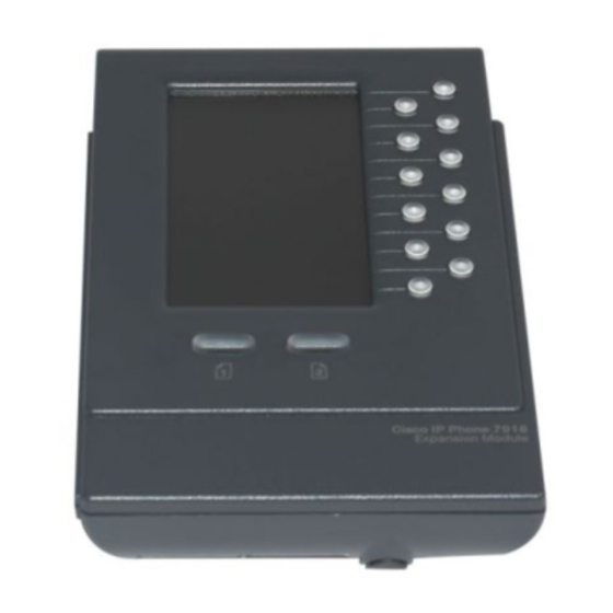
- Page 17 Lighted Buttons—12 buttons. Each button corresponds to one line (just like on the Cisco Unified IP Phone). The lights beneath each button indicate the state of the corresponding line as follows: • Line available: light off • Line in use by you: steady green light •...
- Page 18 Refer to the phone guide for your Cisco Unified IP Phone for instructions about using your phone. The following is a typical scenario when using the Cisco Unified IP Phone and Cisco Unified IP Phone Expansion Module 7916 combination. You receive a call for your Director at extension 12345. You...
-
Page 19: Adjusting The Brightness
Phone services can include, for example, weather, stock quotes, or corporate calendars and directories. Refer to the phone guide for your Cisco Unified IP Phone for more information. Adjusting the Brightness... - Page 20 If you are experiencing other difficulties, contact your system administrator. Technical Specifications for the Cisco Unified IP Phone Expansion Module 7916 This section provides the physical and operating environment specifications for the Cisco Unified IP Phone Expansion Module 7916, as well as the regulatory compliance information.
-
Page 21: Physical And Operating Environment Specifications
48 VDC, 40mA max Cable Specifications The following are the cable specifications for the cables used with the Cisco Unified IP Phone Expansion Module 7916: • 2 RJ-11 jacks with 6-pin connectors for the interface cable connections • 48-V power connector. The diameter of the center pin in the Expansion Module power jack (Switchcraft 712A) is 0.1 in. -
Page 22: Related Documentation
Subscribe to the What’s New in Cisco Product Documentation as a Really Simple Syndication (RSS) feed and set content to be delivered directly to your desktop using a reader application. The RSS feeds are a free service and Cisco currently supports RSS version 2.0. -
Page 23: Cisco One-Year Limited Hardware Warranty Terms
Your formal Warranty Statement, including the warranties and license agreements applicable to Cisco software, is available on Cisco.com. Follow these steps to access and download the Cisco Information Packet and your warranty and license agreements from Cisco.com. - Page 24 The Cisco warranty page appears. d. Read the document online, or click the PDF icon to download and print the document in Adobe Portable Document Format (PDF). You can also contact the Cisco service and support website for assistance: http://www.cisco.com/public/Support_root.shtml. Duration of Hardware Warranty...
- Page 25 Cisco Website at www.cisco.com/go/offices. CCDE, CCVP, Cisco Eos, Cisco StadiumVision, the Cisco logo, DCE, and Welcome to the Human Network are trademarks; Changing the Way We Work, Live, Play, and Learn is a service mark; and Access Registrar, Aironet,...