
Related Manuals for Siemens 181


Summary of Contents for Siemens 181
- Page 1 SIMATIC ET 200SP Analog input module AI 4xRTD/TC 2-/3-/4-wire HF (6ES7134-6JD00-0CA1) Manual Edition 02/2014 Answers for industry.
- Page 2 ___________________ Analog input module AI 4xRTD/TC 2-/3-/4- Preface wire HF (6ES7134-6JD00-0CA1) ___________________ Guide to documentation ___________________ Product overview SIMATIC ___________________ Wiring ET 200SP ___________________ Analog input module Parameters/address space AI 4xRTD/TC 2-/3-/4-wire HF ___________________ (6ES7134-6JD00-0CA1) Interrupts/diagnostics alarms Manual ___________________ Technical specifications ___________________ Parameter data record ___________________...
- Page 3 Legal information Warning notice system This manual contains notices you have to observe in order to ensure your personal safety, as well as to prevent damage to property. The notices referring to your personal safety are highlighted in the manual by a safety alert symbol, notices referring only to property damage have no safety alert symbol.
-
Page 4: Preface
Preface Purpose of the documentation This device manual complements the system manual ET 200SP distributed I/O system (http://support.automation.siemens.com/WW/view/en/58649293). Functions that generally relate to the system are described in this manual. The information provided in this manual and in the system/function manuals supports you in commissioning the system. -
Page 5: Table Of Contents
Table of contents Preface ..............................3 Guide to documentation .......................... 5 Product overview ............................ 7 Properties ............................7 Wiring ..............................10 Pin assignment ..........................10 Schematic circuit diagram ......................12 Parameters/address space ........................13 Measurement types and measuring ranges................13 Parameters .......................... -
Page 6: Guide To Documentation
Guide to documentation Introduction This modular documentation of the SIMATIC products covers diverse topics concerning your automation system. The complete documentation for the ET 200SP distributed I/O system consists of a system manual, function manuals and product manuals. The STEP 7 information system (online help) also supports you during the configuration and programming of your automation system. - Page 7 Guide to documentation Topic Documentation Key contents BaseUnits Manual ET 200SP BaseUnits Technical specifications (http://support.automation.siemens. com/WW/view/en/59753521) Amendments and special Product information on Current information not yet features of the ET 200SP documentation of the ET 200SP documented in the system manuals, distributed I/O system distributed I/O system function manuals, or product...
-
Page 8: Product Overview
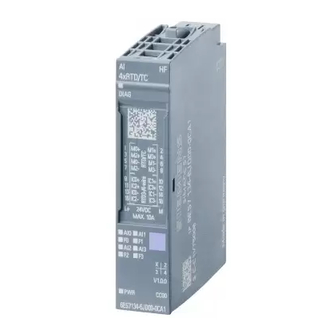
Product overview Properties Article number 6ES7134-6JD00-0CA1 View of the module Figure 2-1 View of the module AI 4×RTD/TC 2-/3-/4-wire HF Analog input module AI 4xRTD/TC 2-/3-/4-wire HF (6ES7134-6JD00-0CA1) Manual, 02/2014, A5E03573289-AD... - Page 9 Product overview 2.1 Properties Properties The module has the following technical properties: ● Analog input module with 4 inputs ● Resolution: Up to 16 bits including sign ● Voltage measurement type can be set per channel ● Resistor measurement type can be set per channel ●...
- Page 10 Product overview 2.1 Properties See also You can find more information on accessories in the ET 200SP distributed I/O system (http://support.automation.siemens.com/WW/view/en/58649293) system manual. Analog input module AI 4xRTD/TC 2-/3-/4-wire HF (6ES7134-6JD00-0CA1) Manual, 02/2014, A5E03573289-AD...
-
Page 11: Wiring
Wiring Pin assignment General pin assignment Table 3- 1 Pin assignment for AI 4xRTD/TC 2-/3-/4-wire HF Pin assignment for AI 4×RTD/TC 2-/3-/4-wire HF (6ES7134-6JD00-0CA1) Terminal Assignment Terminal Assignment Notes BaseUnits Color identification label +: Measuring • line positive, channel n -: Measuring line •... - Page 12 Wiring 3.1 Pin assignment See also ET 200SP distributed I/O system (http://support.automation.siemens.com/WW/view/en/58649293) Analog input module AI 4xRTD/TC 2-/3-/4-wire HF (6ES7134-6JD00-0CA1) Manual, 02/2014, A5E03573289-AD...
-
Page 13: Schematic Circuit Diagram
Wiring 3.2 Schematic circuit diagram Schematic circuit diagram Schematic circuit diagram Figure 3-1 Schematic circuit diagram AI 4×RTD/TC 2-/3-/4-wire HF Analog input module AI 4xRTD/TC 2-/3-/4-wire HF (6ES7134-6JD00-0CA1) Manual, 02/2014, A5E03573289-AD... -
Page 14: Parameters/Address Space
Parameters/address space Measurement types and measuring ranges The following table describes the measuring range and the temperature coefficients you can configure for each measurement type: Table 4- 1 Measurement types and measuring ranges Measurement type Measuring range Temperature coefficient Deactivated –... - Page 15 Parameters/address space 4.1 Measurement types and measuring ranges Special features when using Cu10 sensors ● Choose "Thermal resistor (3-wire connection)" and "Cu10" in the parameter assignment. ● Wire the Cu10 sensor into the 3-wire connection technology. ● During operation, automatic, internal compensation of the line resistance of the missing measuring line takes place.
- Page 16 Parameters/address space 4.1 Measurement types and measuring ranges Special features when using PTC resistors PTCs are suitable for monitoring temperature and/or as thermal protection devices of complex drives or transformer windings. ● Choose "Thermal resistor (2-wire)" and "PTC" in the parameter assignment. ●...
- Page 17 Parameters/address space 4.1 Measurement types and measuring ranges Assignment in the process image input (PII) with SIMATIC S7 Figure 4-1 Assignment in the process image input (PII) Notes on programming ● Bits 0+2 are relevant for evaluation in the process image input. You can monitor, for example, the temperature of a motor using bits 0+2.
- Page 18 Parameters/address space 4.1 Measurement types and measuring ranges Example The diagram shows the temperature curve and the associated switching points. Figure 4-2 Temperature curve with prewarning range See also Technical specifications (Page 40) Analog input module AI 4xRTD/TC 2-/3-/4-wire HF (6ES7134-6JD00-0CA1) Manual, 02/2014, A5E03573289-AD...
-
Page 19: Parameters
Parameters/address space 4.2 Parameters Parameters Parameters of the AI 4xRTD/TC 2-/3-/4-wire HF The following table lists the configurable parameters. The effective range of the configurable parameters depends on the type of configuration. The following configurations are possible: ● Distributed operation on PROFINET IO in an ET 200SP system ●... - Page 20 Parameters/address space 4.2 Parameters Parameter Value range Default Reconfiguration Scope with configuration in RUN software, e.g., STEP 7 (TIA Portal) GSD file GSD file PROFINET IO PROFIBUS DP Type/range of Thermal resistor Channel Channel Deactivated • measurement (4-wire connection) Voltage ±50 mV •...
- Page 21 Parameters/address space 4.2 Parameters Parameter Value range Default Reconfiguration Scope with configuration in RUN software, e.g., STEP 7 (TIA Portal) GSD file GSD file PROFINET IO PROFIBUS DP Type/range of Thermal resistor Thermal resistor Channel Channel measurement (2, 3, 4-wire connection) (4-wire connection) Pt 100 standard Ni 100 climatic range...
- Page 22 Parameters/address space 4.2 Parameters Parameter Value range Default Reconfiguration Scope with configuration in RUN software, e.g., STEP 7 (TIA Portal) GSD file GSD file PROFINET IO PROFIBUS DP Temperature Pt 0.00385055 Channel Channel Pt 0.00385055 • coefficient Pt 0.003916 • Pt 0.003902 •...
- Page 23 Parameters/address space 4.2 Parameters Parameter Value range Default Reconfiguration Scope with configuration in RUN software, e.g., STEP 7 (TIA Portal) GSD file GSD file PROFINET IO PROFIBUS DP Hardware Disable Channel Disable • interrupt high Enable • limit 1 High limit 1 8500 Channel Value...
-
Page 24: Explanation Of Parameters
Parameters/address space 4.3 Explanation of Parameters Explanation of parameters Diagnostics: Missing supply voltage L+ Enabling of the diagnostics for missing or insufficient supply voltage L+. Diagnostics: Reference junction Enabling of the reference junction diagnostics if the reference temperature of the reference junction needs to be determined for the TC channel being operated. - Page 25 Parameters/address space 4.3 Explanation of Parameters Note Shared Device and "Reference channel of group 0, 1, 2, 3" If the transmitter and receiver for the reference junction temperature of a group are assigned to different IO controllers, then both IO controllers must be performing data exchange with the IO device to ensure error-free operation of the temperature compensation.
- Page 26 Parameters/address space 4.3 Explanation of Parameters Setting Description Reference channel of group 0, The channel acts as a receiver for the reference junction 1, 2, 3 temperature of a group. Fixed reference temperature The reference temperature of the thermocouple is set to 0 °C. As a result, no temperature compensation is performed.
- Page 27 Parameters/address space 4.3 Explanation of Parameters Smoothing The individual measured values are smoothed using filtering. The smoothing can be set in 4 levels. Smoothing time = number of module cycles (k) x cycle time of the module. The following figure shows how many module cycles it takes for the smoothed analog value to approach 100%, depending on the configured smoothing.
- Page 28 Parameters/address space 4.3 Explanation of Parameters Measuring range center Determines the temperature over which the scalable measuring range is symmetrically spanned. The value must be within the nominal range of the underlying measuring range. It is specified in integers. Maximum / Minimum Corresponds to overflow / underflow for the scalable measuring range.
-
Page 29: Scalable Measuring Range
Parameters/address space 4.4 Scalable measuring range Scalable measuring range Introduction The scalable measuring range is available for the temperature measuring ranges of thermal resistors (RTD) standard and thermocouples. The measuring ranges for voltage, resistor and thermal resistor climatic are not supported. The scalable measuring range is valid for the following ranges: ●... - Page 30 Parameters/address space 4.4 Scalable measuring range Rules ● The measuring range center must be within the nominal range of the underlying measuring range. It is specified in integers. ● The scalable measuring range is spanned symmetrically over the measuring range ①...
-
Page 31: Configuration
Parameters/address space 4.4 Scalable measuring range 4.4.1 Configuration Requirement You must select a valid temperature measuring range for configuration. Configuration The function is activated using the "Scalable measuring range" parameter. The following figure shows an example of a configuration in STEP 7: Figure 4-5 Configuration for the scalable measuring range Reference... -
Page 32: Evaluating Data Record 235
Parameters/address space 4.4 Scalable measuring range 4.4.2 Evaluating data record 235 Evaluation in the user program In the user program, you can evaluate the status and the limits of the scalable measuring range with data record 235, which may result by reaching underflow/overflow. Structure of data record 235 Figure 4-6 Structure of data record 235... - Page 33 Parameters/address space 4.4 Scalable measuring range Parameters The figure below shows the structure of the parameter. If the corresponding bit is set to "1", the parameter is activated. * x = 2 + (channel number x 8) Figure 4-8 Structure of data record 235 - channel parameter byte x to x+7 Description of the parameters Table 4- 9 Description of the parameters from data record 235...
- Page 34 Parameters/address space 4.4 Scalable measuring range Example The following example shows the values for a thermal resistor Pt 100 Standard, °C: Table 4- 10 Example of a thermal resistor Pt 100 Standard Hex. value Dec. value Evaluation of data record 235 V0.0 8 bytes Scalable measuring range active and clipped (clipping)
-
Page 35: Address Space
Parameters/address space 4.5 Address space Address space Address space of the analog input module AI 4×RTD/TC 2-/3-/4-wire HF The following figure shows the assignment of the address space with value status (Quality Information (QI)). The addresses for the value status are only available if the value status is enabled. -
Page 36: Interrupts/Diagnostics Alarms
Interrupts/diagnostics alarms Status and error display LED display The figure below shows the LED displays of the AI 4xRTD/TC 2-/3-/4-wire HF: ① DIAG (green/red) ② Channel status (green) ③ Channel error (red) ④ PWR (green) Figure 5-1 LED display Analog input module AI 4xRTD/TC 2-/3-/4-wire HF (6ES7134-6JD00-0CA1) Manual, 02/2014, A5E03573289-AD... - Page 37 Interrupts/diagnostics alarms 5.1 Status and error display Meaning of the LED displays The following tables contain the meaning of the status and error displays. Remedies for diagnostics alarms can be found in section Diagnostics alarms (Page 38). DIAG LED Table 5- 1 Error display of the DIAG LED DIAG LED Meaning...
-
Page 38: Interrupts
Interrupts/diagnostics alarms 5.2 Interrupts Interrupts Evaluating hardware interrupts with IO controller The module generates a hardware interrupt at the following events: ● Violation of low limit 1 ● Violation of high limit 1 ● Violation of low limit 2 ● Violation of high limit 2 You can obtain detailed information on the event in the hardware interrupt organization block with the "RALARM"... -
Page 39: Diagnostics Alarms
Interrupts/diagnostics alarms 5.3 Diagnostics alarms Diagnostic error interrupt The module generates a diagnostic error interrupt at the following events: ● Channel temporarily unavailable ● Hardware interrupt lost ● Reference channel error ● Error ● Violation of low limit ● Violation of high limit ●... - Page 40 Interrupts/diagnostics alarms 5.3 Diagnostics alarms Diagnostics alarms Error code Meaning Remedy Parameter assignment The module cannot evaluate parameters Correct the configuration • error for the channel: Module plugged in does (comparison of preset and actual not match the configuration. setup). Incorrect parameter assignment.
-
Page 41: Technical Specifications
Technical specifications Technical specifications Technical specifications of AI 4×RTD/TC 2-/3-/4-wire HF 6ES7134-6JD00-0CA1 Product type designation AI 4xRTD/TC 2-/3-/4-wire HF General information Firmware version V2.0 Usable BaseUnits BU type A0, A1 Product function I&M data Yes; I&M0 to I&M3 Engineering with STEP 7 TIA Portal can be configured/integrated as of version V12 SP1 / V13 STEP 7 can be configured/integrated as of version... - Page 42 Technical specifications 6.1 Technical specifications 6ES7134-6JD00-0CA1 Analog inputs Number of analog inputs Maximum permissible input voltage for voltage input 30 V (destruction limit) Constant measurement current for resistance-type sensor, typ. 2 mA Cycle time (all channels), min. Sum of the basic conversion times and additional processing times (depending on the parameter assignment of the activated...
- Page 43 Technical specifications 6.1 Technical specifications 6ES7134-6JD00-0CA1 Type TXK/TXK(L) according to GOST Yes; 16 bits incl. sign Input resistance (Type TXK/TXK(L) according to GOST) 1 MΩ Input ranges (rated values), resistance thermometer Cu 10 Yes; 16 bits incl. sign Input resistance (Cu 10) 1 MΩ...
- Page 44 Technical specifications 6.1 Technical specifications 6ES7134-6JD00-0CA1 Yes; with BaseUnit type A1 Internal reference junction • Reference channel of the group • 4; group 0 to 3 Number of reference channel groups • Fixed reference temperature • Resistance thermometer (RTD) Maximum permissible input voltage for voltage input 30 V (destruction limit) Technical unit for temperature measurement...
- Page 45 Technical specifications 6.1 Technical specifications 6ES7134-6JD00-0CA1 Operational limit in entire temperature range Voltage in relation to input range, (+/-) ± 0.1% Resistance in relation to input range, (+/-) ± 0.1% Basic error limit (operational limit at 25 °C) Voltage in relation to input range, (+/-) ±...
- Page 46 Technical specifications 6.1 Technical specifications Operational and basic error limits for resistance thermometers Error limits for resistance thermometers Operational limit (in the entire temperature range, in relation to input range) ±1.0 K Pt 100, Pt 200, Pt 500, Pt 1000 standard •...
- Page 47 Technical specifications 6.1 Technical specifications Operational and basic error limits for thermocouples Error limits for thermocouples Operational limit for thermocouples (in the entire temperature range, in ±1.5 K relation to the input range) Operational limit for type C thermocouples (in the entire temperature ±...
-
Page 48: Parameter Data Record
Parameter data record Dependencies when configuring with GSD file When configuring the module with a GSD file, remember that the settings of some parameters are dependent on each other. Configuring with a PROFINET GSD file The table lists the properties and their dependencies on the measurement type and measuring range for PROFINET. - Page 49 Parameter data record A.1 Dependencies when configuring with GSD file Measurement Measuring range Temperature Reference junction Temperature unit Conductor type coefficient resistance (3-wire Cu 10 climatic Cu 0.00427 connection) Thermal resistor Pt100 Pt 0.00385055 No reference Degrees Celsius x (with 2-wire (2, 3, 4-wire Pt200 Pt 0.003916...
- Page 50 Parameter data record A.1 Dependencies when configuring with GSD file Configuring with a PROFINET GSD file The table lists the properties and their dependencies on the measurement type for PROFINET. Table A- 2 Dependencies on the measurement type Measurement type Scalable Measuring range Diagnostics...
- Page 51 Parameter data record A.1 Dependencies when configuring with GSD file Measurement Measuring Temperature Slot Temperature Diagnostics type range coefficient reference unit Underflow Wire Missing Reference junction / overflow break supply junction voltage Resistor – – (2-wire connection) Thermal Pt100 Pt 0.00385055 Reference Degrees –...
- Page 52 Parameter data record A.1 Dependencies when configuring with GSD file Measurement Measuring Temperature Slot Temperature Diagnostics type range coefficient reference unit Underflow Wire Missing Reference junction / overflow break supply junction voltage Thermal Cu 10 Cu 0.00427 Degrees – resistor climatic reference Celsius...
-
Page 53: Parameter Assignment And Structure Of Parameter Data Record
Parameter data record A.2 Parameter assignment and structure of parameter data record Parameter assignment and structure of parameter data record The data records of the module have an identical structure, regardless of whether you configure the module with PROFIBUS DP or PROFINET IO. Parameter assignment in the user program The module parameter settings can be changed in RUN (for example, the voltage or current values of selected channels can be edited in RUN without having an effect on the other... - Page 54 Parameter data record A.2 Parameter assignment and structure of parameter data record Header information The figure below shows the structure of the header information. Figure A-2 Header information Analog input module AI 4xRTD/TC 2-/3-/4-wire HF (6ES7134-6JD00-0CA1) Manual, 02/2014, A5E03573289-AD...
- Page 55 Parameter data record A.2 Parameter assignment and structure of parameter data record Parameters The figure below shows the structure of the parameters for channels 0 to 3. You can activate a parameter by setting the corresponding bit to "1". * x = 2 + (channel number * 22); channel number = 0 to 3 Analog input module AI 4xRTD/TC 2-/3-/4-wire HF (6ES7134-6JD00-0CA1) Manual, 02/2014, A5E03573289-AD...
- Page 56 Parameter data record A.2 Parameter assignment and structure of parameter data record Analog input module AI 4xRTD/TC 2-/3-/4-wire HF (6ES7134-6JD00-0CA1) Manual, 02/2014, A5E03573289-AD...
- Page 57 Parameter data record A.2 Parameter assignment and structure of parameter data record Figure A-3 Structure of byte x to x+21 for channel 0 to 3 Codes for measurement type The following table contains the codes for the measurement types of the analog input module.
- Page 58 Parameter data record A.2 Parameter assignment and structure of parameter data record Codes for measuring range The following table contains the codes for the measuring ranges of the analog input module. You must enter these codes at byte x+1 (see previous figure). Table A- 4 Codes for measuring range Measuring range...
- Page 59 Parameter data record A.2 Parameter assignment and structure of parameter data record Measuring range Code Thermal resistor Cu 10 climatic 0000 1110 Cu 10 standard 0000 1111 Thermocouple Type B 0000 0000 Type N 0000 0001 Type E 0000 0010 Type R 0000 0011 Type S...
- Page 60 Parameter data record A.2 Parameter assignment and structure of parameter data record Limits for hardware interrupts The following tables contain the permitted limits for hardware interrupts (in each case, the usable value is given). The limits depend on the selected measurement type and the selected measuring range.
- Page 61 Parameter data record A.2 Parameter assignment and structure of parameter data record Table A- 10 Limits for thermocouple types N and TXK Thermocouple Type N Type TXK °C °F °C °F 15499 28219 18231 10499 19219 13231 Overflow -2699 -4539 -1999 -3279 Underflow...
-
Page 62: Switchable Wire Break Check
Parameter data record A.3 Switchable wire break check Switchable wire break check Function The "Switchable wire break check" is available for thermocouples. It switches off the wire break check for the module. This is required, for example, to calibrate thermocouples, since the test current necessary for a wire break check leads to measurement errors during calibration. -
Page 63: Representation Of Analog Values
Representation of analog values This appendix shows the analog values for all measuring ranges supported by the analog input module AI 4xRTD/TC 2-/3-/4-wire HF. Measured value resolution The resolution of the analog values differs depending on the analog module and its assigned parameters. -
Page 64: Representation Of Input Ranges
Representation of analog values B.1 Representation of input ranges Representation of input ranges In the following tables, you can find the digitized representation of the bipolar and unipolar input ranges. The resolution is 16 bits. Table B- 2 Bipolar input ranges Dec. -
Page 65: Representation Of Analog Values In Voltage Measuring Ranges
Representation of analog values B.2 Representation of analog values in voltage measuring ranges Representation of analog values in voltage measuring ranges The following tables list the decimal and hexadecimal values (codes) of the possible voltage measuring ranges. Table B- 4 Voltage measuring range ±1 V Values Voltage measuring range... -
Page 66: Representation Of Analog Values For Resistance-Type Sensors
Representation of analog values B.3 Representation of analog values for resistance-type sensors Representation of analog values for resistance-type sensors The following tables list the decimal and hexadecimal values (codes) of the possible resistance-type sensor ranges. Table B- 6 Resistance-type sensors from 150 Ω to 6000 Ω Values Resistance-type sensor range Range... -
Page 67: Representation Of Analog Values For Thermal Resistors
Representation of analog values B.4 Representation of analog values for thermal resistors Representation of analog values for thermal resistors Note A higher resolution can be configured for the measuring range for the standard resistance thermometers, see section Scalable measuring range (Page 28). The tables below list the decimal and hexadecimal values (codes) of the thermal resistors. - Page 68 Representation of analog values B.4 Representation of analog values for thermal resistors Table B- 9 Thermal resistor Ni 100, 120, 200, 500, 1000, LG-Ni 1000 standard Ni x00 Values Ni x00 Values Ni x00 Values Range standard in standard in standard in Dec.
- Page 69 Representation of analog values B.4 Representation of analog values for thermal resistors Table B- 11 Thermal resistor Cu 10 standard Cu 10 Values Cu 10 Values Cu 10 Values Range standard standard standard Dec. Hex. Dec. Hex. Dec. Hex. in °C in °F in K (1 digit =...
-
Page 70: Representation Of Analog Values For Thermocouples
Representation of analog values B.5 Representation of analog values for thermocouples Representation of analog values for thermocouples Note A higher resolution can be configured for thermocouples, see section Scalable measuring range (Page 28). The tables below list the decimal and hexadecimal values (codes) of the thermocouples. Table B- 13 Thermocouple type B Type B... - Page 71 Representation of analog values B.5 Representation of analog values for thermocouples Table B- 15 Thermocouple type E Type E Values Type E Values Type E Values Range in °C in °F in K Dec. Hex. Dec. Hex. Dec. Hex. > 1200.0 32767 7FFF >...
- Page 72 Representation of analog values B.5 Representation of analog values for thermocouples Table B- 18 Thermocouple type L Type L Values Type L Values Type L Values Range in °C in °F in K Dec. Hex. Dec. Hex. Dec. Hex. > 1150.0 32767 7FFF >...
- Page 73 Representation of analog values B.5 Representation of analog values for thermocouples Table B- 21 Thermocouple type T Type T Values Type T Values Type T Values Range in °C in °F in K Dec. Hex. Dec. Hex. Dec. Hex. > 540.0 32767 7FFF >...