Table of Contents
Quick Links
D9142F
Operation and Installation
Table of Contents:
I.
II.
III.
Description ...................................................................................................................2
........................................................................................................ 3
Installing the D9142F .................................................................................... 3
1. Mounting the Enclosure .......................................................................... 3
2. Installing the D9142M .............................................................................. 4
3. Installing the D1601 ................................................................................. 4
Connecting AC Power .................................................................................. 4
Batteries ....................................................................................................... 7
1.
Battery Connection ............................................................................... 7
2.
Battery Supervision .............................................................................. 8
3.
Stand-by Battery Calculations ............................................................. 8
Connecting Auxiliary Devices ..................................................................... 9
Power Supply Supervision .......................................................................... 9
LED Indicators ............................................................................................ 11
Switched Output Control ........................................................................... 12
Specifications .................................................................................................... 13
24VDC Power Supply
Table of Contents

Related Manuals for Bosch 24VDC


Summary of Contents for Bosch 24VDC
-
Page 1: Table Of Contents
D9142F 24VDC Power Supply Operation and Installation Table of Contents: Description ........................2 Installation ......................3 Installing the D9142F ..................3 1. Mounting the Enclosure ................3 2. Installing the D9142M ................4 3. Installing the D1601 ................. 4 Connecting AC Power .................. 4 Batteries ....................... -
Page 2: Description
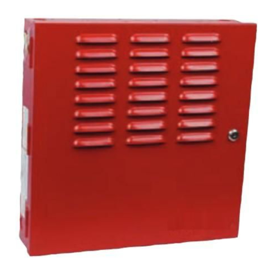
The D9142F Power Supply is shipped in three separate packages. The D9142M and installation instructions come in one package. The D8109L comes in a second package and the D1601 transformer comes in a third package. Figure 1: D9142F System D9142F Operation and Installation F01U036364-03 Page 2 © Bosch Security Systems, Inc. -
Page 3: Installation
Power and Trouble LED assembly Installation The D9142F typically is installed adjacent to the Control Communicator. It is compatible with all Bosch Security Systems, Inc. Control Panels but should only be used with a listed panel for fire alarm applications. -
Page 4: Installing The D9142M
Call a licensed electrician to troubleshoot any electrical problem. 5. Insert the fuse into the F1 socket. 6. Replace the protective cover. 7. Turn the 120 VAC circuit breaker ON. D9142F Operation and Installation F01U036364-03 Page 4 © Bosch Security Systems, Inc. - Page 5 5. Insert the fuse into the F1 socket. 6. Replace the protective cover. 7. Turn the 120 VAC circuit breaker ON. 8. Observe the green AC power LED should be ON. D9142F Operation and Installation © Bosch Security Systems, Inc. Page 5 F01U036364-03...
- Page 6 If the D9142F is to be used to power the panel the D8109L should be mounted next to the control’s enclosure and joined with conduit. D9142F Operation and Installation F01U036364-03 Page 6 © Bosch Security Systems, Inc.
-
Page 7: Installing The Batteries
• Do not mix battery sizes, types, or manufacturers when connecting to a power supply. • Wear insulated gloves and safety goggles while handling Consult battery manufacturer instructions for further information about batteries and applicable safety precautions. D9142F Operation and Installation © Bosch Security Systems, Inc. Page 7 F01U036364-03... -
Page 8: Battery Supervision
0.135 A from the supply continuously. 7 amp hours also provide up to 3 A of alarm power for indicating devices for five minutes at the end of the stand-by period. D9142F Operation and Installation F01U036364-03 Page 8 © Bosch Security Systems, Inc. -
Page 9: Connecting Auxiliary Devices
• On Board AC Fuse Failure • Power Output Fault • Battery Test Failure • Battery Trouble: Low, Missing or Shorted Figure 6: Connecting Power Output to Devices D9142F Operation and Installation © Bosch Security Systems, Inc. Page 9 F01U036364-03... - Page 10 This relay can be used as a common trouble indicator. To activate the relay for a specific trouble condition, move the switch to the on position. For the factory default settings see Figure 8. Figure 8: Dip Switch Settings Default D9142F Operation and Installation F01U036364-03 Page 10 © Bosch Security Systems, Inc.
-
Page 11: Led Indicators
D8109L enclosure. 2. Mount the LED assembly with the three screws provided. 3. Connect the LED assembly wire harness to J5 on the D9142F board. Figure 10: Status LED's D9142F Operation and Installation © Bosch Security Systems, Inc. Page 11 F01U036364-03... -
Page 12: Switched Output Control
3) Relocate the control panel with respect to the radio/television. If necessary, the installer should consult an experienced radio/television technician for additional suggestions, or send for the “Interference Handbook” prepared by the Federal Communications Commission. © 2008 Bosch Security Systems, Inc. F01U036364-03 2/08...