Honeywell 4600g User Manual
Honeywell commercial/retail/industrial area imager user's guide
Hide thumbs
Also See for 4600g:
- Quick start manual (21 pages) ,
- User manual (248 pages) ,
- Specifications (2 pages)

Related Manuals for Honeywell 4600g


Summary of Contents for Honeywell 4600g
- Page 1 4600rp, 4600g/4600r, 4800i Commercial/Retail/Industrial Area Imager User’s Guide ™...
- Page 2 Disclaimer Honeywell International Inc. (“Honeywell”) reserves the right to make changes in specifications and other information contained in this document without prior notice, and the reader should in all cases consult Honeywell to determine whether any such changes have been made. The information in this publication does not represent a commitment on the part of Honeywell.
- Page 3 This equipment has been tested and found to comply with the limits for a Class A digital device, pursuant to part 15 of the FCC Rules. These limits are designed to provide reasonable protection against harmful interference when the equipment is operated in a commercial environment. This equipment generates, uses, and can radiate radio frequency energy and, if not installed and used in accordance with the instruction manual, may cause harmful interference to radio communications.
- Page 4 For further information please contact: Honeywell Imaging & Mobility Europe BV Nijverheidsweg 9-13 5627 BT Eindhoven The Netherlands Honeywell International Inc. shall not be liable for use of our product with equipment (i.e., power supplies, personal computers, etc.) that is not CE marked and does not comply with the Low Voltage Directive.
- Page 5 Please refer to the product packaging for patent information. Solids and Water Protection The 4600g/4600r has a rating of IP41, immunity of foreign particles and dripping water. The 4800i has a rating of IP54, immunity of windblown dust penetration and...
-
Page 7: Table Of Contents
Table of Contents Chapter 1 - Getting Started About This Manual ... 1-1 Unpacking the Imager ... 1-1 Imager Models ... 1-2 Imager Identification ... 1-3 Connecting the Imager with USB ... 1-5 Connecting the Imager with RS-232 Serial Port ... 1-6 Connecting the Imager with RS-232 Wedge ... - Page 8 Wand Emulation ... 2-13 Data Block Size ... 2-13 Delay Between Blocks ... 2-14 Overall Checksum ... 2-14 Wand Emulation Transmission Rate ... 2-15 Wand Emulation Polarity ... 2-15 Wand Emulation Idle... 2-16 Chapter 3 - Output Good Read Indicators... 3-1 Beeper –...
- Page 9 Aimer Mode ... 3-12 Centering... 3-12 Decode Search Mode ... 3-14 Preferred Symbology ... 3-15 Output Sequence Overview ... 3-17 Output Sequence Editor ... 3-19 Require Output Sequence... 3-19 Multiple Symbols ... 3-20 No Read ... 3-21 Print Weight... 3-21 Video Reverse...
- Page 10 Chapter 5 - Data Formatting Data Format Editor Introduction... 5-1 To Add a Data Format ... 5-1 Other Programming Selections... 5-2 Data Format Editor Commands ... 5-2 Data Format Editor ... 5-5 Data Formatter... 5-5 Alternate Data Formats... 5-6 Chapter 6 - Secondary Interface Secondary RS-232 Connection ...
- Page 11 Interleaved 2 of 5 ... 7-8 Code 93 ... 7-10 Straight 2 of 5 Industrial ... 7-11 Straight 2 of 5 IATA (Two-Bar Start/Stop) ... 7-12 Matrix 2 of 5 ... 7-13 Code 11 ... 7-13 Code 128 ... 7-15 ISBT 128 Concatenation ...
- Page 12 Postal Codes ... 7-38 Intelligent Mail Barcode ... 7-38 ID-tag (UPU 4-State) ... 7-39 Postnet... 7-39 Planet Code ... 7-40 British Post... 7-41 Canadian Post ... 7-41 Kix (Netherlands) Post ... 7-41 Australian Post... 7-41 Japanese Post ... 7-43 China Post ... 7-43 Korea Post ...
- Page 13 OCR Templates ... 9-3 Creating an OCR Template... 9-3 Stringing Together Multiple Formats (Creating “Or” Statements) ... 9-5 OCR User-Defined Variables ... 9-6 Reading Multi-Row OCR ... 9-7 OCR Check Character ... 9-7 OCR Modulo 10 Check Character... 9-8 OCR Modulo 36 Check Character... 9-8 OCR User-Defined Check Character ...
- Page 14 Examples of Query Commands ... 12-3 Trigger Commands ... 12-4 Resetting the Standard Product Defaults ... 12-4 Menu Commands ... 12-4 Chapter 13 - Product Specifications 4600g and 4600r... 13-1 4800i ... 13-2 Standard Cable Pinouts... 13-3 Keyboard Wedge ... 13-3 Wand Emulation ... 13-4 Serial Output ...
- Page 15 Appendix A Symbology Chart... A-1 ASCII Conversion Chart (Code Page 1252) ... A-4 Code Page Mapping of Printed Barcodes ... A-6 Sample Symbols OCR Programming Chart Programming Chart...
-
Page 17: Chapter 1 - Getting Started
Getting Started About This Manual This User’s Guide provides installation and programming instructions for the 4000 Series imagers. Product specifications, dimensions, warranty, and cus- tomer support information are also included. Honeywell barcode imagers are factory programmed for the most common ter- minal and communications settings. -
Page 18: Imager Models
Imager Models The chart below lists the interfaces that can be used with your imager. Refer to Chapter 6 for programming information regarding secondary interfaces. Models Primary 4600gXX03XX True RS-232 4800iXX03XX 4600gXX05XX Keyboard wedge, TTL level 4800iXX05XX 232, TTL level 232 serial wedge, IBM 4683, wand emula- tion, USB keyboard, USB HID, USB retail (IBM SurePOS),... -
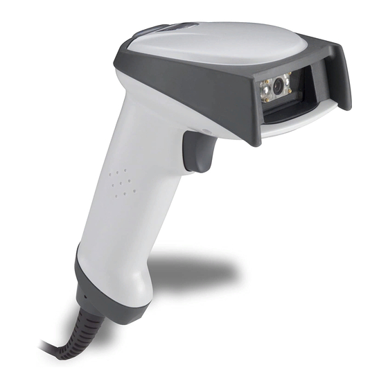
Page 19: Imager Identification
Imager Identification Compliance Label location Item Number, Serial Number and Revision Information location 1 - 3... - Page 20 Connecting the Imager with Keyboard Wedge Note: See "Imager Models" your imager. An imager can be connected between the keyboard and PC as a “keyboard wedge,” plugged into the serial port, or connected to a portable data terminal in wand emulation or non decoded output mode. The following is an example of a keyboard wedge connection: 1.
-
Page 21: Connecting The Imager With Usb
Connecting the Imager with USB Note: See "Imager Models" your imager. An imager can be connected to the USB port of a computer. 1. Connect the appropriate interface cable to the imager first, then to the com- puter. 2. Program the imager for a USB interface using the Plug and Play barcodes beginning on page 1-9. -
Page 22: Connecting The Imager With Rs-232 Serial Port
Connecting the Imager with RS-232 Serial Port Note: See "Imager Models" your imager. 1. Turn off power to the terminal/computer. 2. Connect the appropriate interface cable to the imager. Note: For the imager to work properly, you must have the correct cable for your type of terminal/computer. - Page 23 1. Turn off power to the computer. 2. Disconnect the existing serial cable from the computer. 3. Connect the appropriate interface cable to the imager. Note: For the imager to work properly, you must have the correct cable for your type of computer.
-
Page 24: Programming The Interface - Plug And Play
Programming the Interface - Plug and Play Plug and Play barcodes provide instant imager set up for commonly used inter- faces. Note: After you scan one of the codes, power cycle the host terminal to have the interface in effect. Note: See "Imager Models"... -
Page 25: Usb Connection
USB Connection IBM SurePos Scan one of the following “Plug and Play” codes to program the imager for IBM SurePos (USB handheld imager) or IBM SurePos (USB Tabletop imager). Note: After scanning one of these codes, you must power cycle the cash register. -
Page 26: Usb Pc Or Macintosh Keyboard
USB PC or Macintosh Scan one of the following codes to program the imager for USB PC Keyboard or USB Macintosh Keyboard. Scanning these codes adds a CR and selects the terminal ID (USB PC Keyboard - 124, USB Macintosh Keyboard - 125). USB Keyboard (PC) USB Japanese Keyboard (PC) USB HID... -
Page 27: Rs-232 Serial Port Connection
CTS/RTS Emulation ACK/NAK Mode RS-232 Serial Port Connection All communication parameters between the imager and terminal must match for correct data transfer through the serial port using RS-232 protocol. Scanning the RS-232 interface barcode programs the imager for an RS-232 interface at 38,400 baud, parity–none, 8 data bits, 1 stop bit, and adds a suffix of a CR LF. -
Page 28: Serial Wedge Data Transmission Port
Serial Wedge Data Transmission Port Using the following barcodes, set the port to which you want the scanned data to transmit. Port 1 corresponds to P1 on the output cable and Port 2 corre- sponds to P2 on the output cable. Choosing Both sends scanned data to P1 and P2. -
Page 29: Wand Emulation Connection
Each of the previous barcodes also programs the following suffixes for each symbology: Symbology EAN-8 EAN-13 UPC-A UPC-E Code 39 Interleaved 2 of 5 Code 128 IBM 4683 Port 9B HHBCR-2 Interface The IBM 4683 Port 9B HHBCR-2 Interface barcode also programs the following suffixes for each symbology: Symbology EAN-8... -
Page 30: Reading Techniques
25 inches per second, Output Polarity to black high, and Idle State to high. (If you want to change the terminal ID only , without changing any other imager set- tings, please refer to Wand Emulation Connection on page 2-12.) Wand Emulation Plug &... - Page 31 from the target, pull the trigger, and center the aiming beam on the symbol. If the code being scanned is highly reflective (e.g., laminated), it may be neces- sary to tilt the code +5° to prevent unwanted reflection. 1 - 15...
- Page 32 1 - 16...
-
Page 33: Chapter 2 - Terminal Interfaces
Terminal Interfaces Terminal ID If your interface is not covered by a Plug and Play barcode from Chapter 1, then refer to Supported Terminals on page 2-2 through page 2-3, and locate the Ter- minal ID number for your PC. Scan the Terminal ID barcode below, then scan the numeric barcode(s) from the Programming Chart inside the back cover of... -
Page 34: Supported Terminals
Supported Terminals Note: See "Imager Models" your imager. Terminal Esprit Heath Zenith Heath Zenith IBM 102 key IBM 122 key IBM 122 key IBM 122 key IBM 122 key IBM DOS/V 106 key IBM SurePOS IBM SurePOS IBM Thinkpad IBM Thinkpad IBM Thinkpad I/O 122 key Lee Data... - Page 35 Wand Emulation (Code 39 Format) Wand Emulation (Same Code Format) * Default for 4600g/4600r/4600rp/4800iXX 05XX models. It is best to use the Plug and Play barcodes, beginning on ning the terminal ID listed in this table. ** Default for 4600g/4800iXX 03XX models...
-
Page 36: Keyboard Country
Keyboard Country Scan the appropriate country code below to program the keyboard for your country. As a general rule, the following characters are supported, but need special care for countries other than the United States: @ | $ # { } [ ] = / ‘ \ < > ~ * United States Brazil Czech Republic... - Page 37 Keyboard Country (continued) Italy Latin America Netherlands (Dutch) Norway Poland Portugal Romania Russia Slovakia Spain Sweden Switzerland (German) 2 - 5...
-
Page 38: Keyboard Style
Keyboard Country (continued) Turkey F Turkey Q U.K. Please refer to the Honeywell website (www.honeywell.com/aidc) for complete keyboard country support information and applicable interfaces. If you need to program a keyboard for a country other than one listed above, scan the Pro- gram Keyboard Country barcode below, then scan the numeric barcode(s) for the appropriate country from the inside back cover, then the Save barcode. -
Page 39: Keyboard Modifiers
Shift Lock is used when you normally have the Shift Lock key on (not common to U.S. keyboards). Shift Lock Automatic Caps Lock is used if you change the Caps Lock key on and off. The software tracks and reflects if you have Caps Lock on or off (AT and PS/2 only). - Page 40 support all keyboard country codes. New users should use the Windows mode. Refer to Keyboard Function Relationships, page 10-1 for CTRL+ ASCII Values. Default = Off Windows Mode Control + ASCII Mode On * Control + ASCII Mode Off DOS Mode Control + ASCII Mode On Turbo Mode: The imager sends characters to a terminal faster.
- Page 41 Automatic Direct Connect Mode: This selection can be used if you have an IBM AT style terminal and the system is dropping characters. Default = Off Automatic Direct Connect Mode On * Automatic Direct Connect Mode Off 2 - 9...
-
Page 42: Rs-232 Baud Rate
RS-232 Baud Rate Baud Rate sends the data from the imager to the terminal at the specified rate. The host terminal must be set for the same baud rate as the imager. Default = 38,400. 1200 4800 19200 57,600 RS-232 Word Length: Data Bits, Stop Bits, and Parity Data Bits sets the word length at 7 or 8 bits of data per character. -
Page 43: Rs-232 Receiver Time-Out
Parity provides a means of checking character bit patterns for validity. Default = None. 7 Data, 1 Stop, Parity Even 7 Data, 1 Stop, Parity Odd 7 Data, 2 Stop Parity None 8 Data, 1 Stop, Parity Even 8 Data, 1 Stop, Parity Odd RS-232 Receiver Time-Out The unit stays awake to receive data until the RS-232 Receiver Time-Out expires. -
Page 44: Rs-232 Handshaking
receiver time-out by scanning the barcode below, then scanning digits from the inside back cover of this manual, then scanning Save . The range is 0 to 300 seconds. Default = 0 seconds (no time-out - always on). RS-232 Handshaking RS-232 Handshaking allows control of data transmission from the Imager using software commands from the host device. -
Page 45: Wand Emulation
In Wand Emulation mode, the imager decodes the barcode then sends data in the same format as a wand imager. The Code 39 Format converts all symbolo- gies to Code 39. The Same Code Format transmits UPC, EAN, Code 128, Codabar, and Inter- leaved 2 of 5 without any changes, but converts all other symbologies to Code 39. -
Page 46: Delay Between Blocks
Delay Between Blocks This sets the delay time between data blocks. Default = 50ms. 150ms Overall Checksum When this option is turned on, a computed check character is added at the end of the entire message. The check character is the character which when Exclu- sive-OR’d with every preceding character of the message yields a result of 0x00 (00H). -
Page 47: Wand Emulation Transmission Rate
Wand Emulation Transmission Rate The Transmission Rate is limited by the terminal’s ability to receive data without dropping characters. Default = 25 inches/second. Wand Emulation Polarity The Polarity can be sent as standard with black bars high, or reversed with white bars high. -
Page 48: Wand Emulation Idle
Wand Emulation Idle The idle describes the state of the imager when no data is being transmitted. When in Wand Emulation mode, you must set the imager’s idle state to match the idle state for the device to which the imager is connected. Default = Idle High . -
Page 49: Chapter 3 - Output
Beeper Volume – Good Read The beeper volume codes modify the volume of the beep the imager emits on a good read. Default = Medium for the 4600g / 4600r / 4600rp ; High for the 4800i . Medium High... -
Page 50: Beeper Pitch - Good Read
Beeper Pitch – Good Read The beeper pitch codes modify the pitch (frequency) of the beep the imager emits on a good read. Default = Medium. Low (1600 Hz) * Medium (3250 Hz) High (4200 Hz) Beeper Duration – Good Read The beeper duration codes modify the length of the beep the imager emits on a good read. -
Page 51: Good Read Delay
LED flashes are in sync with one another. To change the number of beeps, scan the barcodebarcode below and then scan a digit (1-9) barcode and the Save barcode on the Programming Chart inside the back cover of this manual. Default = One. -
Page 52: Trigger Modes
Trigger Modes Manual/Serial Trigger You can activate the imager either by pressing the trigger, or using a serial trig- ger command (see Trigger Commands on page 12-4). When in manual trigger mode, the imager scans until a barcode is read, or until the trigger is released. When in serial mode, the imager scans until a barcode has been read or until the deactivate command is sent. -
Page 53: In-Stand Sensor Mode (4600R Only)
Low Power Time-Out Timer Scan the Low Power Time-Out barcode to change the time-out duration (in sec- onds). Then scan the time-out duration (from 0-300 seconds) from the inside back cover, and Save . Default = 120 seconds. If the unit remains idle during the low power time-out interval, the unit goes into low power mode. -
Page 54: Scan Stand Symbol
When a unit is in Scan Stand mode, it remains idle as long as it sees the Scan Stand symbol. (See Scan Stand Symbol is presented, the imager is triggered to read the new code. Note: The imager automatically adjusts the illumination LEDs to the lowest light level possible to maintain a good lock on the Scan Stand symbol. -
Page 55: Presentation Led Behavior After Decode
Presentation LED Behavior after Decode When an imager is in presentation mode, the LEDs remain on and continue scanning for a short time after a barcode is decoded. If you wish to turn the LEDs off immediately after a barcode is decoded, scan the LEDs Off barcode, below. -
Page 56: Image Snap And Ship
Image Snap and Ship Image Snap and Ship tells the imager to take a picture (rather than read a bar- code) the next time the trigger is pressed. Once the picture is snapped, it is shipped to the host system as a jpeg file. The imager then reverts to barcode reading for the next trigger press. -
Page 57: User-Specified Reread Delay
Reread Delay only works when in Presentation™ Mode (page 3-7). Short (500 ms) Long (1000 ms) User-Specified Reread Delay If you want to set your own length for the reread delay, scan the barcode below, then set the delay (from 0-30,000 milliseconds) by scanning digits from the inside back cover, then scanning Save . -
Page 58: Illumination Lights
If you have an aimer delay programmed (see aimer will be at 100% power during the delay, regardless of the LED Power Level. Note: If you scan the Off barcode, both the aimer and illumination lights turn off, making it impossible to scan barcodes in low light. To turn the LED Power Level back on, move to a brightly lit area and scan either the Low or the High barcode below. -
Page 59: Imager Time-Out
Imager Time-Out Imager Time-Out powers down the imager after the unit has been idle for the specified time. To prevent the imager from powering down, set this time-out to 0. Scan the barcode below, then set the time-out by scanning digits (from 0 - 999,999 ms) from the inside back cover, then scanning Save . -
Page 60: Aimer Mode
5X00 engines. Refer to the Revision on page 11-1 for information on determining the engine in your unit. The 4600g, 4600r, 4800i, and 4600rp do not allow concurrent aimer mode. The Aimer Mode feature allows you to lower peak current during scanning by alternating the aimer and illumination LEDs. - Page 61 Barcode 1 Barcode 2 The default centering window is a 128x96 pixel area in the center of the imager’s field of view. The following diagram illustrates the default top, bottom, left, and right pixel positions, measured from the top and the left side of the imager’s field of view, which is 640 by 480 pixels.
-
Page 62: Decode Search Mode
Scan Centering On , then scan one of the following barcodes to change the top, bottom, left, or right of the centering window. Then scan the percent you want to shift the centering window using digits on the inside back cover of this man- ual. -
Page 63: Preferred Symbology
Quick Omnidirectional - This is an abbreviated search for barcode features around the center region of an image. This mode quickly reads all symbologies in any orientation. The Quick Omnidirectional mode may miss some off-center symbols, as well as larger Data Matrix and QR Code symbols. Quick Omnidirectional Advanced Linear Decoding - Performs quick horizontal linear scans in a cen- ter band of the image. - Page 64 Scan a barcode below to enable or disable Preferred Symbology. Preferred Symbology On * Preferred Symbology Off High Priority Symbology To specify the high priority symbology, scan the High Priority Symbology bar- code below. On the Symbology Chart on page A-1, find the symbology you want to set as high priority.
-
Page 65: Output Sequence Overview
Preferred Symbology Default Scan the barcode below to set all Preferred Symbology entries to their default values. Output Sequence Overview Require Output Sequence When turned off, the barcode data will be output to the host as the Imager decodes it. When turned on, all output data must conform to an edited sequence or the imager will not transmit the output data to the host device. - Page 66 value that represents the character(s) you want to match. Use the Program- ming Chart to read the alphanumeric combination that represents the ASCII characters. (99 is the Universal number, indicating all characters.) 5. End Output Sequence Editor Scan F F to enter an Output Sequence for an additional symbology, or Save to save your entries.
-
Page 67: Output Sequence Editor
9999 code length that must match for Code 93, 9999 = all lengths start character match for Code 93, 43h = “C” termination string for third code To program the previous example using specific lengths, you would have to count any programmed prefixes, suffixes, or formatted characters as part of the length. -
Page 68: Multiple Symbols
When the output sequence is Off , the barcode data is output to the host as the imager decodes it. Note: This selection is unavailable when the Multiple Symbols Selection is turned on. Required On/Not Required *Off Multiple Symbols Note: This feature does not work when the Imager is in Low Power mode. When this programming selection is turned On , it allows you to read multiple symbols with a single pull of the Imager’s trigger. -
Page 69: No Read
No Read With No Read turned On , the Imager notifies you if a code cannot be read. If using a Quick*View Scan Data Window, an “NR” appears when a code cannot be read. If No Read is turned Off , the “NR” will not appear. * Off If you want a different notation than “NR,”... -
Page 70: Working Orientation
Video Reverse is used to allow the imager to read barcodes that are inverted. The “Off” barcode below is an example of this type of barcode. If additional menuing is required, Video Reverse must be disabled to read the menu bar- codes and then re-enabled after menuing is completed. - Page 71 * Upright Rotate Code Clockwise 90° (Rotate Imager Counterclockwise) Upside Down Rotate Code Counterclockwise 90° (Rotate Imager Clockwise) 3 - 23...
- Page 72 3 - 24...
-
Page 73: Chapter 4 - Data Editing
Data Editing Prefix/Suffix Overview When a barcode is scanned, additional information is sent to the host computer along with the barcode data. This group of barcode data and additional, user-defined data is called a “message string.” The selections in this section are used to build the user-defined data into the message string. -
Page 74: To Add A Prefix Or Suffix
To Add a Prefix or Suffix: Step 1. Scan the Add Prefix or Add Suffix symbol Step 2. Determine the 2 digit Hex value from the Symbology Chart (included in Appendix A) for the symbology to which you want to apply the prefix or suffix. -
Page 75: To Clear One Or All Prefixes Or Suffixes
To Clear One or All Prefixes or Suffixes: You can clear a single prefix or suffix, or clear all prefixes/suffixes for a symbol- ogy. When you Clear One Prefix (Suffix), the specific character you select is deleted from the symbology you want. When you Clear All Prefixes (Suffixes), all the prefixes or suffixes for a symbology are deleted. -
Page 76: Prefix Selections
Prefix Selections Add Prefix Clear One Prefix Clear All Prefixes Suffix Selections Add Suffix Clear One Suffix Clear All Suffixes Function Code Transmit When this selection is enabled and function codes are contained within the scanned data, the imager transmits the function code to the terminal. Charts of these function codes are provided in Supported Interface Keys starting on... -
Page 77: Intercharacter, Interfunction, And Intermessage Delays
Intercharacter, Interfunction, and Intermessage Delays Some terminals drop information (characters) if data comes through too quickly. Intercharacter, interfunction, and intermessage delays slow the transmission of data, increasing data integrity. Each delay is composed of a 5 millisecond step. You can program up to 99 steps (of 5 ms each) for a range of 0-495 ms. -
Page 78: Interfunction Delay
Next, scan the Character to Trigger Delay barcode, then the 2-digit hex value for the ASCII character that will trigger the delay ASCII Conversion Chart (Code Page 1252), page A-4. Delay Length Character to Trigger Delay To remove this delay, scan the Delay Length barcode, and set the number of steps to 0. -
Page 79: Intermessage Delay
Intermessage Delay An intermessage delay of up to 495 milliseconds (in 5 ms steps) may be placed between each scan transmission. Scan the Intermessage Delay barcode below, then scan the number of 5 millisecond steps (0-99), and the Save bar- code using the Programming Chart inside the back cover of this manual. - Page 80 4 - 8...
-
Page 81: Chapter 5 - Data Formatting
Data Formatting Data Format Editor Introduction You may use the Data Format Editor to change the imager’s output. For exam- ple, you can use the Data Format Editor to insert characters at certain points in barcode data as it is scanned. The selections in the following pages are used only if you wish to alter the output. -
Page 82: Other Programming Selections
Step 4. Code I.D. Appendix A, find the symbology to which you want to apply the data format. Locate the Hex value for that symbology and scan the 2 digit hex value from the manual. Step 5. Length Specify what length (up to 9999 characters) of data will be acceptable for this symbology. - Page 83 F4 Send “xx” character “nn” times (Insert) leaving cursor in current cursor posi- tion. Syntax = F4xxnn (xx stands for the hex value for an ASCII code, see ASCII Conversion Chart (Code Page numeric value (00-99) for the number of times it should be sent.) E9 Send all but the last “nn”...
- Page 84 ters to be replaced and xx through zz and zz E5 Terminates character replacement. Syntax = E5. FE Compare character in current cursor position to the character “xx.” If char- acters are equal, increment cursor. If characters are not equal, no format match.
-
Page 85: Data Format Editor
Data Format Editor Enter Data Format * Default Data Format Clear One Data Format Clear All Data Formats Save Discard Data Formatter When Data Formatter is turned off, the barcode data is output to the host as read (including prefixes and suffixes). Choose one of the following options. Default = Data Formatter On, but Not Required. -
Page 86: Alternate Data Formats
Alternate Data Formats Alternate formats allow you “single shot” capability to scan one barcode using a different data format than your primary format. When data formats are pro- grammed (see page 5-1), you must input whether you are programming the pri- mary format, or an alternate format numbered 1, 2, or 3. -
Page 87: Chapter 6 - Secondary Interface
Secondary Interface By switching secondary interface cables, the imager can, for example, commu- nicate with a portable data terminal (secondary interface) in addition to the host terminal (primary interface). Refer to the table below for interfaces supported by your model. Some features don’t apply if the interface is not supported by your model. -
Page 88: Secondary Rs-232 Connection
You can temporarily disable the secondary interface, but still retain the second- ary interface settings in the imager’s memory by scanning the Disable barcode below. To re-enable the secondary interface, scan the Enable barcode. Default =Disable . * Disable Enable Secondary RS-232 Connection All communication parameters between the imager and terminal must match for correct data transfer through the serial port using RS-232 protocol. -
Page 89: Wand Emulation Multi Block
The Code 39 Format barcode below sets the terminal ID to 61, and the Same Code Format barcode sets the terminal ID to 64. Wand Emulation Same Code Format Wand Emulation Multi Block Note: See "Imager Models" your imager. Note: Changing secondary wand emulation settings also changes the primary wand emulation settings (see Delay Between Blocks This sets the delay time between data blocks. -
Page 90: Overall Checksum
Overall Checksum When this option is turned on, a computed check character is added at the end of the entire message. The check character is the character which when Exclu- sive-OR’d with every preceding character of the message yields a result of 0x00 (00H). -
Page 91: Wand Emulation Polarity
Wand Emulation Polarity The Polarity can be sent as standard with black bars high, or reversed with white bars high. Default = Black High. * Black High White High Wand Emulation Idle The idle describes the state of the imager when no data is being transmitted. When in Wand Emulation mode, you must set the imager’s idle state to match the idle state for the device to which the imager is connected. -
Page 92: Secondary Trigger Mode
Note: Programming Read Time-Out in the secondary interface also programs it in the primary interface. Manual Trigger, Low Power Note:Does not apply to the 4600g/4600r/4600rp/4800i with Advanced Illumina- tion. The imager powers down until the trigger is pulled. When the trigger is pulled, the imager powers up and operates until there is no triggering for the time set with the Low Power Time-Out barcode below. -
Page 93: Hands Free Time-Out
Low Power Time-Out Timer Scan the Low Power Time-Out barcode to change the time-out duration (in sec- onds). Then scan the time-out duration (from 0-300 seconds) from the inside back cover, and Save . Default = 120 seconds. If the unit remains idle during the low power time-out interval, the unit goes into low power mode. -
Page 94: Scan Stand Mode
Scan Stand Mode Note: Scan Stand Mode is only available for non-advanced illumination units with software revision 31205480-090 or older. Refer to the Software Revision software in your unit. When a unit is in Scan Stand mode, it remains idle as long as it sees the Scan Stand symbol. - Page 95 Symbologies This programming section contains the following menu selections. Refer to Chapter 12 for settings and defaults. • All Symbologies • Intelligent Mail Barcode • Australian Post • Aztec Code • British Post • Canadian Post • China Post • Codabar •...
-
Page 96: All Symbologies
All Symbologies If you want to decode all the symbologies allowable for your imager, scan the All Symbologies On code. If on the other hand, you want to decode only a particular symbology, scan All Symbologies Off followed by the On symbol for that particular symbology. -
Page 97: Codabar
CodabarCodabar * On Codabar Start/Stop Characters Start/Stop characters identify the leading and trailing ends of the barcode. You may either transmit, or not transmit Start/Stop characters. Default = Don’t Transmit . Transmit * Don’t Transmit Codabar Check Character Codabar check characters are created using different “modulos.”... -
Page 98: Codabar Concatenation
When Check Character is set to Validate, but Don’t Transmit , the unit will only read Codabar barcodes printed with a check character, but will not transmit the check character with the scanned data. * No Check Character Validate Modulo 16, but Don’t Transmit Validate Modulo 16 and Transmit... -
Page 99: Code 39
Codabar Message Length Scan the barcodes below to change the message length. Refer to Message Length Description (page 7-2) for additional information. Minimum and Maximum lengths = 2-60. Minimum Default = 4, Maximum Default = 60. Minimum Message Length Maximum Message Length Code 39 <... - Page 100 When Check Character is set to Validate, but Don’t Transmit, the unit only reads Code 39 barcodes printed with a check character, but will not transmit the check character with the scanned data. When Check Character is set to Validate and Transmit, the imager only reads Code 39 barcodes printed with a check character, and will transmit this charac- ter at the end of the scanned data.
-
Page 101: Code 32 Pharmaceutical (Paraf)
Code 32 Pharmaceutical (PARAF) Code 32 Pharmaceutical is a form of the Code 39 symbology used by Italian pharmacies. This symbology is also known as PARAF. Note: Trioptic Code (page Pharmaceutical codes. Full ASCII If Full ASCII Code 39 decoding is enabled, certain character pairs within the barcode symbol will be interpreted as a single character. -
Page 102: Code 39 Code Page
Character pairs /M and /N decode as a minus sign and period respectively. Character pairs /P through /Y decode as 0 through 9. Full ASCII On * Full ASCII Off Code 39 Code Page Code pages define the mapping of character codes to characters. If the data received does not display with the proper characters, it may be because the barcode being scanned was created using a code page that is different from the one the host program is expecting. - Page 103 When Check Digit is set to Validate, but Don’t Transmit, the unit only reads Interleaved 2 of 5 barcodes printed with a check digit, but will not transmit the check digit with the scanned data. When Check Digit is set to Validate and Transmit, the imager only reads Inter- leaved 2 of 5 barcodes printed with a check digit, and will transmit this digit at the end of the scanned data.
-
Page 104: Code 93
Code 93 < Default All Code 93 Settings > Code 93 * On Code 93 Message Length Scan the barcodes below to change the message length. Refer to Message Length Description (page 7-2) for additional information. Minimum and Maximum lengths = 0-80. Minimum Default = 0, Maximum Default = 80. Minimum Message Length Maximum Message Length Code 93 Code Page... -
Page 105: Straight 2 Of 5 Industrial
Straight 2 of 5 IndustrialStraight 2 of 5 Industrial * Off Straight 2 of 5 Industrial Message Length Scan the barcodes below to change the message length. Refer to Message Length Description (page 7-2) for additional information. -
Page 106: Straight 2 Of 5 Iata (Two-Bar Start/Stop)
Straight 2 of 5 IATA (Two-Bar Start/Stop)Straight 2 of 5 IATA * Off Straight 2 of 5 IATA Message Length Scan the barcodes below to change the message length. Refer to Message Length Description (page 7-2) for additional information. -
Page 107: Matrix 2 Of 5
Matrix 2 of 5Matrix 2 of 5 * Off Matrix 2 of 5 Message Length Scan the barcodes below to change the message length. Refer to Message Length Description (page 7-2) for additional information. Minimum and Maximum lengths = 1-80. -
Page 108: Code 11
Code 11 * Off Check Digits Required This option sets whether 1 or 2 check digits are required with Code 11 bar- codes. Default = Two Check Digits. One Check Digit * Two Check Digits Code 11 Message Length Scan the barcodes below to change the message length. Refer to Message Length Description (page 7-2) for additional information. -
Page 109: Code 128
Code 128Code 128 * On ISBT 128 Concatenation In 1994 the International Society of Blood Transfusion (ISBT) ratified a standard for communicating critical blood information in a uniform manner. The use of ISBT formats requires a paid license. The ISBT 128 Application Specification describes 1) the critical data elements for labeling blood products, 2) the current recommendation to use Code 128 due to its high degree of security and its space-efficient design, 3) a variation of Code 128 that supports concatenation... - Page 110 Code 128 Message Length Scan the barcodes below to change the message length. Refer to Message Length Description (page 7-2) for additional information. Minimum and Maximum lengths = 0-80. Minimum Default = 0, Maximum Default = 80. Minimum Message Length Maximum Message Length Code 128 Code Page Code pages define the mapping of character codes to characters.
-
Page 111: Telepen
TelepenTelepen * Off Telepen Output Using AIM Telepen Output, the imager reads symbols with start/stop pattern 1 and decodes them as standard full ASCII (start/stop pattern 1). When Original Telepen Output is selected, the imager reads symbols with start/stop pattern 1 and decodes them as compressed numeric with optional full ASCII (start/stop pattern 2). -
Page 112: Upc-A
UPC-AUPC-A * On UPC-A Check Digit This selection allows you to specify whether the check digit should be transmit- ted at the end of the scanned data or not. Default = On . * On UPC-A Number System The numeric system digit of a U.P.C. -
Page 113: Upc-A Addenda
UPC-A Addenda This selection adds 2 or 5 digits to the end of all scanned UPC-A data. Default = Off for both 2 Digit and 5 Digit Addenda. 2 Digit Addenda On 5 Digit Addenda On UPC-A Addenda Required When Required is scanned, the imager will only read UPC-A barcodes that have addenda. -
Page 114: Upc-A/Ean-13
UPC-A/EAN-13 with Extended Coupon Code Use the following codes to enable or disable UPC-A and EAN-13 with Extended Coupon Code. Default = On. * On UPC-E0UPC-E0 Most U.P.C. barcodes lead with the 0 number system. For these codes, use the UPC-E0 selection. - Page 115 UPC-E0 Addenda Required When Addenda Required is set to on, the imager will only read UPC-E bar- codes that have addenda. Default = Not Required. Required UPC-E0 Addenda Separator When this feature is on, there is a space between the data from the barcode and the data from the addenda.
-
Page 116: Upc-E1
UPC-E0 Number System The numeric system digit of a U.P.C. symbol is normally transmitted at the beginning of the scanned data, but the unit can be programmed so it will not transmit it. Default = On. * On UPC-E0 Addenda This selection adds 2 or 5 digits to the end of all scanned UPC-E data. -
Page 117: Ean/Jan-13
EAN/JAN-13EAN/JAN-13 * On EAN/JAN-13 Check Digit This selection allows you to specify whether the check digit should be transmit- ted at the end of the scanned data or not. Default = On. * On 7 - 23... - Page 118 EAN/JAN-13 Addenda This selection adds 2 or 5 digits to the end of all scanned EAN/JAN-13 data. Default = Off for both 2 Digit and 5 Digit Addenda. 2 Digit Addenda On 5 Digit Addenda On EAN/JAN-13 Addenda Required When Addenda Required is set to on, the imager will only read EAN/JAN-13 barcodes that have addenda.
-
Page 119: Isbn Translate
ISBN Translate This selection causes EAN-13 Bookland symbols to be translated into their equivalent ISBN number format. Default = Off. * Off EAN/JAN-8EAN/JAN-8 * On EAN/JAN-8 Check Digit This selection allows you to specify whether the check digit should be transmit- ted at the end of the scanned data or not. -
Page 120: Ean/Jan-8 Addenda
EAN/JAN-8 Addenda This selection adds 2 or 5 digits to the end of all scanned EAN/JAN-8 data. Default = Off for both 2 Digit and 5 Digit Addenda. 2 Digit Addenda On 5 Digit Addenda On EAN/JAN-8 Addenda Required When Addenda Required is set to on, the imager will only read EAN/JAN-8 bar- codes that have addenda. -
Page 121: Msi
* Off MSI Check Character Different types of check characters are used with MSI barcodes. You can program the imager to read MSI barcodes with Type 10 check characters. Default = Validate Type 10, but Don’t Transmit. When Check Character is set to Validate and Transmit , the imager will only read MSI barcodes printed with the specified type check character, and will transmit this character at the end of the scanned data. -
Page 122: Plessey Code
MSI Message Length Scan the barcodes below to change the message length. Refer to Length Description (page 7-2) for additional information. Minimum and Maximum lengths = 4-48. Minimum Default = 4, Maximum Default = 48. Minimum Message Length Plessey Code... -
Page 123: Gs1 Databar Omnidirectional
GS1 DataBar Omnidirectional < Default All GS1 DataBar Omnidirectional Settings > GS1 DataBar Omnidirectional * On GS1 DataBar Limited < Default All GS1 DataBar Limited Settings > GS1 DataBar Limited * On GS1 DataBar Expanded < Default All GS1 DataBar Expanded Settings > 7 - 29... - Page 124 GS1 DataBar Expanded * On GS1 DataBar Expanded Message Length Scan the barcodes below to change the message length. Refer to Message Length Description (page 7-2) for additional information. Minimum and Maximum lengths = 4-74. Minimum Default = 4, Maximum Default = 74. Minimum Message Length Maximum Message Length 7 - 30...
-
Page 125: Posicode
PosiCodePosiCode A and B * On You have to have PosiCode A and B on to read any of the PosiCode symbolo- gies. A and B On (No Limited) A and B and Limited A On (Limited B Off) * A and B and Limited B On (Limited A Off) -
Page 126: Trioptic Code
Trioptic Code Note: If you are going to scan Code 32 Pharmaceutical codes Trioptic Code must be off. Trioptic Code is used for labeling magnetic storage media. Codablock FCodablock F Codablock F Message Length Scan the barcodes below to change the message length. -
Page 127: Code 16K
Code 16KCode 16K * Off Code 16K Message Length Scan the barcodes below to change the message length. Refer to Message Length Description (page 7-2) for additional information. Minimum and Maximum lengths = 0-160. Minimum Default = 1, Maximum Default = 160. Minimum Message Length Maximum Message Length 7 - 33... -
Page 128: Code 49
Code 49Code 49 * On Code 49 Message Length Scan the barcodes below to change the message length. Refer to Message Length Description (page 7-2) for additional information. Minimum and Maximum lengths = 1-81. Minimum Default = 1, Maximum Default = 81. Minimum Message Length Maximum Message Length 7 - 34... -
Page 129: Pdf417
PDF417 < Default All PDF417 Settings > PDF417 * On PDF417 Message Length Scan the barcodes below to change the message length. Refer to Message Length Description (page 7-2) for additional information. Minimum and Maximum lengths = 1-2750. Minimum Default = 1, Maximum Default = 2750. Minimum Message Length Maximum Message Length 7 - 35... -
Page 130: Micropdf417
MicroPDF417 < Default All MicroPDF417 Settings > MicroPDF417 MicroPDF417 Message Length Scan the barcodes below to change the message length. Refer to Length Description (page 7-2) for additional information. Minimum and Maximum lengths = 1-366. Minimum Default = 1, Maximum Default = 366. Minimum Message Length GS1 Composite Codes Linear codes are combined with a unique 2D composite component to form a... -
Page 131: Upc/Ean Version
UPC/EAN Version Scan the UPC/EAN Version On barcode to decode GS1 Composite symbols that have a UPC or EAN linear component. (This does not affect GS1 Compos- ite symbols with a UCC/EAN-128 or GS1 linear component. If either of these codes are the linear component, either Code 128 or the correct GS1 code must be enabled.) UPC/EAN Version On... -
Page 132: Tcif Linked Code 39 (Tlc39)
reported as “]e0.” Any application that accepts GS1 data can be simplified since it only needs to recognize one data carrier type. Default = GS1 Emulation Off . GS1 Emulation * GS1 Emulation Off TCIF Linked Code 39 (TLC39) This code is a composite code since it has a Code 39 linear component and a MicroPDF417 stacked code component. -
Page 133: Id-Tag (Upu 4-State)
ID-tag (UPU 4-State) Note: You may enable the ID-tag (UPU 4-State) if you have firmware with a base number of 31205480. Refer to the page 11-2 for information on determining the firmware revision in your unit. Postnet Postnet Check Digit This selection allows you to specify whether the check digit should be transmit- ted at the end of the scanned data. -
Page 134: Planet Code
Planet Code * Off Planet Code Check Digit This selection allows you to specify whether the check digit should be transmit- ted at the end of the scanned data. Transmit Check Digit * Don’t Transmit Check Digit 7 - 40... -
Page 135: British Post
British Post Canadian Post Kix (Netherlands) Post Note: Kix code can misread when scanned sideways or upside down. Use Working Orientation, page 3-22, if your Kix codes will not usually be presented upright to the imager. Australian Post * Off * Off * Off * Off... - Page 136 Australian Post Interpretation This option controls what interpretation is applied to customer fields in Austra- lian 4-State symbols. Bar Output lists the bar patterns in “0123” format. Numeric N Table causes that field to be interpreted as numeric data using the N Table.
-
Page 137: Japanese Post
Japanese Post * Off China PostChina Post * Off China Post Message Length Scan the barcodes below to change the message length. Refer to Message Length Description (page 7-2) for additional information. Minimum and Maximum lengths = 2-80. -
Page 138: Korea Post
Korea PostKorea Post * Off Korea Post Message Length Scan the barcodes below to change the message length. Refer to Message Length Description (page 7-2) for additional information. Minimum and Maxi- mum lengths = 2-80. Minimum Default = 4, Maximum Default = 48. Minimum Message Length Maximum Message Length 7 - 44... -
Page 139: Qr Code
QR Code < Default All QR Code Settings > QR Code This selection applies to both QR Code and Micro QR Code. * On Note: The default applies to firmware with a base number of 31205480. Refer to the Show Software Revision determining the firmware revision in your unit QR Code Message Length Scan the barcodes below to change the message length. -
Page 140: Data Matrix
Data Matrix < Default All Data Matrix Settings > Data Matrix * On Data Matrix Message Length Scan the barcodes below to change the message length. Refer to Message Length Description (page 7-2) for additional information. Minimum and Maximum lengths = 1-1500. Minimum Default = 1, Maximum Default = 1500. Minimum Message Length Maximum Message Length 7 - 46... -
Page 141: Maxicode
MaxiCode < Default All MaxiCode Settings > MaxiCode * On MaxiCode Message Length Scan the barcodes below to change the message length. Refer to Message Length Description (page 7-2) for additional information. Minimum and Maximum lengths = 1-150. Minimum Default = 1, Maximum Default = 150. Minimum Message Length Maximum Message Length 7 - 47... -
Page 142: Aztec Code
Aztec Code < Default All Aztec Code Settings > Aztec Code * On Aztec Code Message Length Scan the barcodes below to change the message length. Refer to Message Length Description (page 7-2) for additional information. Minimum and Maximum lengths = 1-3750. Minimum Default = 1, Maximum Default = 3750. Minimum Message Length Maximum Message Length Aztec Runes... -
Page 143: Chapter 8 - Imaging Commands
Imaging Commands The image scanner is like a digital camera in the way it captures, manipulates, and transfers images. The following commands allow you to alter the way the imager performs these functions. Single-Use Basis Imaging Commands with their modifiers send instructions to the imager on a single-use basis, and take effect for a single image capture. -
Page 144: Image Snap - Imgsnp
Step 1 - Take a Picture Using IMGSNP Image Snap - IMGSNP An image is taken whenever the hardware button is pressed, or when the Image Snap (IMGSNP) command is processed. The image snap command has many different modifiers that can be used to change the look of the image in memory. - Page 145 L - LED State Determines if the LEDs should be on or off, and when. Ambient illumination (0L) is preferred for taking pictures of color documents, such as ID cards, especially when the imager is in a stand. LED illumination (1L) is preferred when the imager is handheld.
- Page 146 G - Gain Gain is used in Manual Style only (2P). Like a volume control, the gain modifier boosts the signal and multiplies the pixel value. As you increase the gain, the noise in an image is also amplified. No gain (default) Medium gain Heavy gain Maximum gain...
-
Page 147: Image Ship - Imgshp
% - Target Set Point Percentage Sets the target point for the light and dark values in the captured image. A setting of 75% means 75% of the pixels are at or below the target white value, and 25% of the pixels are above the target white value. Altering this setting from the default is not recommended under normal circumstances. -
Page 148: Imgshp Modifiers
IMGSHP Modifiers A - Infinity Filter Enhances pictures taken from very long distances (greater than 10 feet or 3m). The Infinity Filter should not be used with Infinity filter off (default) Infinity filter on Example of Infinity Filter off (0A) from approximately 12 feet (3.66m) away: C - Compensation Flattens the image to account for variations in illumination across the image. - Page 149 E - Edge Sharpen An edge sharpen filter cleans up the edges of an image, making it look cleaner and sharper. While edge sharpening does make the image look cleaner, it also removes some fine detail from the original image. The strength of the edge sharpen filter can be entered from 1 to 24.
- Page 150 H - Histogram Stretch Increases the contrast of the transmitted image. Not available with some image formats. No stretch (default) Histogram stretch Example of Histogram Stretch at 0H: I - Invert Image Invert image is used to rotate the image around the X or Y axis. Invert around the X axis (flips picture upside down) Invert around the Y axis (flips picture left to right) Example of image not...
- Page 151 IF- Noise Reduction Used to reduce the salt and pepper noise in an image. No salt and pepper noise reduction (default) Salt and pepper noise reduction Example of Noise Reduction Off (0if): IR - Image Rotate Image as snapped (rightside up) (default) Rotate image 90 degrees to the right Rotate image 180 degrees (upside down) Rotate image 90 degrees to the left...
- Page 152 J - JPEG Image Quality Sets the desired quality when the JPEG image format is selected. Higher numbers result in higher quality, but larger files. Smaller numbers result in greater amounts of lossy compression, faster transmission times, lower quality, but smaller files. (Default = 50) Image is compressed as much as possible while preserving quality factor of n ( n = 0 - 100) worst quality (smallest file)
- Page 153 The bottom edge of the shipped image corresponds to row n - 1 of the image in memory. Range: 000 - 480. (Default = all rows) Uncropped Image: Example of Image Crop set to 200B: Alternately, specify the number of pixels to cut from the outside margin of the image;...
- Page 154 S - Pixel Ship Pixel Ship sizes an image in proportion to its original size. It decimates the image by shipping only certain, regularly spaced pixels. For example, 4S would transmit every fourth pixel from every fourth line. The smaller number of pixels shipped, the smaller the image, however, after a certain point the image becomes unusable.
- Page 155 Apply document image filter using grayscale threshold n. Use lower numbers when the image contrast is lower. 1U will have a similar effect to setting Range: 0-255. Example of Document Image Filter set to 0U: V - Blur Image Smooths transitions by averaging the pixels next to the hard edges of defined lines and shaded areas in an image.
-
Page 156: Intelligent Signature Capture - Imgbox
W - Histogram Ship A histogram gives a quick picture of the tonal range of an image, or key type. A low-key image has detail concentrated in the shadows; a high-key image has detail concentrated in the highlights; and an average-key image has detail concentrated in the midtones. -
Page 157: Imgbox Modifiers
To see this example, align the aimer with the signature area (not with the bar- code), then press the trigger. Send the following IMGBOX command string after the button push: Note: Case is not important in the command string. It is used here only for clarity. The following image is captured: The IMGBOX commands have many different modifiers that can be used to change the size and appearance of the signature image output by the imager. - Page 158 B - Output Image Height This option is used to size the image vertically. If using this option, set the resolution (R) to zero. Example of Image Height set to 50B: Example of Image Height set to 100B: D - Pixel Depth This indicates the number of bits per pixel in the transmitted image, which defines whether it will be grayscale or black and white.
- Page 159 K - Gamma Correction Gamma measures the brightness of midtone values produced by the image. You can brighten or darken an image using gamma correction. A higher gamma correction yields an overall brighter image. The lower the setting, the darker the image. The optimal setting for text images is 50K. Gamma correction off (default) Apply gamma correction for brightening typical document image Apply gamma correction factor n ( n = 1-255)
- Page 160 R - Resolution of Signature Capture Area The resolution is the number of pixels that the imager outputs per each minimum bar width. The higher the value for R, the higher the quality of the image, but also the larger the file size. Values begin at 1000. The imager automatically inserts a decimal point between the first and second digit.
- Page 161 X - Horizontal Barcode Offset The horizontal barcode offset allows you to offset the horizontal center of the signature capture area. Positive values move the horizontal center to the right and negative values to the left. Measurements are in multiples of the minimum bar width.
- Page 162 8 - 20...
-
Page 163: Chapter 9 - Ocr Programming
OCR Programming Use this section to program the Imager for optical character recognition (OCR). The 2D imager reads 6 to 60 point OCR typeface. Note: OCR is not as secure as barcodes. To enhance security in OCR applications, create an OCR template to match the data, and print an OCR check character. -
Page 164: U.s. Currency Font
OCR-B On allows you to scan characters in the OCR-B font. The default set- ting allows you to scan any eight digit combination. If you have created an OCR template, character combinations that fit the template can be scanned (see Creating an OCR Template, page 9-3). -
Page 165: Semi Font
SEMI Font SEMI Font On allows you to scan the SEMI font used in the semiconductor industry. SEMI Font On All OCR Off turns off all OCR capability in the imager, so the imager will be able to scan linear, stacked, matrix, and composite barcodes, but not OCR fonts. However, any OCR templates you have created will be retained in memory. - Page 166 Template Characters represents any alphanumeric character (digit or letter) represents that a check character is verified but not transmitted represents any digit represents any available OCR character represents character from user-defined variable “g” represents character from user-defined variable “h” represents character from user-defined variable “g” or “h” represents that a check character is verified but transmitted represents any uppercase letter marks the start of a new template...
-
Page 167: Stringing Together Multiple Formats (Creating "Or" Statements)
Character Match Sequences This method is used if you need a template that shows a specific character in a specific position. Put the character in uppercase in the template at the required position (template characters are always lower case). Example: You need to read three variable digits, three specific characters (ABC), followed by three variable digits. -
Page 168: Ocr User-Defined Variables
To create this template, you would enable the OCR-A font. Scan the Enter OCR Template symbol in the back of this manual eight times, then scan the t to create the “or” Chart statement. Then you would scan the characters for the second template. Scan d four times, scan l two times , then scan d two more times. -
Page 169: Reading Multi-Row Ocr
Reading Multi-Row OCR The imager is capable of decoding multi-row OCR text. Note: Reading rows longer than sixteen characters is not recommended. Consider the following example. This example shows serial commands as they would be entered using Quick*View. Example: You need to read multiple rows of OCR-A data as shown below: First, enable the OCR-A font. -
Page 170: Ocr Modulo 10 Check Character
Example: You need to read any combination of seven digits, with a modulo 10 check character in the eighth position. The template would be: To create this template, you would enable the OCR-A font. Scan the Modulo 10 Check Character symbol. Then scan the Enter OCR Template symbol, and scan the d from the c once. -
Page 171: Weighting Options
Also enter the OCR template: Enable the OCR-A font, then scan the following string: The imager performs the following check character computation: (6 + 5 + 1 + 2 +3 + 5 + 1 + X) modulo 11 = 0 Since the result is zero, the message is considered to be valid, so the reader outputs the message: 6512351 Programming a User-Defined Check Character... - Page 172 3-1-3-1 Weighted Modulo 10 Check Character Starting with the check character and working backward through the message, the imager applies a multiplier of 1, then 3, then 1, then 3, and so on. This is the checking scheme used in many GS1 symbologies, including U.P.C. and Interleaved 2 of 5 (when a check digit is invoked).
-
Page 173: Ocr Isbn Application Example
Then scan the string below: The reader performs the check character computation below: (0 x 1 + 1 x 2 + 2 x 1 + 8 x 2 + 4 x 1 + 5 x 2 + 4 x 1) modulo 10 = (0 + 2 + 2 + (1 + 6) + 4 + (1 + 0) + 4) modulo 10 Since the result is zero, the message is considered to be valid, so the reader outputs the message: 012845... - Page 174 4. Scan the symbol below to set up three templates to handle the ISBN number, the three digit price field, and the four digit price field. 5. Finally, set up the ISBN check digit, which is a special position-weighted modulo 11 checksum. The imager automatically invokes the ISBN checksum for template rows that are: 1.) at least fourteen characters long, 2.) whose first four characters are the letters “ISBN,”...
-
Page 175: Ocr Template Codes
OCR Template Codes Note: Reading more than three rows of OCR is not recommended. Contact the factory if you have an application that requires reading four or more rows of OCR. Enter OCR Template Enter User-Defined † Variable “h” † One or more two-digit numbers and Save are required after reading this pro- gramming symbol. - Page 176 9 - 14...
-
Page 177: Chapter 10 - Interface Keys
Interface Keys Keyboard Function Relationships The following Keyboard Function Code, Hex/ASCII Value, and Full ASCII “CTRL”+ relationships apply to all terminals that can be used with the imager. Refer to page 2-7 enable Control + ASCII mode. Function Code HEX/ASCII Value Full ASCII “CTRL”... - Page 178 The last five characters in the Full ASCII “CTRL”+ column ( [ \ ] 6 - ), apply to US only. The following chart indicates the equivalents of these five characters for different countries. Country United States Belgium Scandinavia France Germany Italy Switzerland...
-
Page 179: Supported Interface Keys
Supported Interface Keys IBM AT/XT and PS/2 Compatibles, WYSE PC/AT ASCII Supported Keys Reserved Enter (KP) Cap Lock ALT make ALT break CTRL make CTRL break CR/Enter Reserved Reserved Delete CR/Enter Insert Escape Home Print Back Space Back Tab * IBM 3191/92, 3471/72, 3196/97, 3476/77, Telex (all models) IBM XTs and IBM, DDC, Memorex Compatibles... - Page 180 Supported Interface Keys IBM, Memorex Telex (102)* ASCII Supported Keys Reserved Enter New Line Tab/Field Forward Delete Field Exit Insert Clear Error Reset Home Print Back Space Back Tab * IBM 3196/97, 3476/77, 3191/92, 3471/72, Memorex Telex (all models) with 102 key keyboards ** Memorex Telex with 88 key keyboards 10 - 4...
- Page 181 Supported Interface Keys Esprit 200, 400 ANSI ASCII Supported Keys Reserved New Line New Line New Line Escape Insert Back Space Back Tab Esprit 200, 400 Esprit 200, 400 ASCII Supported Keys Supported Keys Reserved Reserved New Line New Line New Line New Line Delete...
- Page 182 Supported Interface Keys Apple Mac/iMac ASCII Supported Keys Reserved Enter/Numpad Enter CAPS ALT make ALT break CNTRL make CNTRL break RETURN APPLE make APPLE break RETURN Ins Help Home Prnt Scrn BACKSPACE LSHIFT TAB BACKSPACE 10 - 6...
-
Page 183: Chapter 11 - Utilities
Utilities To Add a Test Code I.D. Prefix to All Symbologies This selection allows you to turn on transmission of a Code I.D. before the decoded symbology. (See the Symbology Chart, included in the A, page A-1) for the single character code that identifies each symbology.) This action first clears all current prefixes, then programs a Code I.D. -
Page 184: Show Scan Driver Revision
Show Scan Driver Revision Scan the barcode below to output the scan driver revision. The scan driver con- trols image capture. You may use the Show Scan Driver Revision option if you have firmware with a base number of 31205480. Refer to the Show Software Revision below for information on determining the firmware revision in your unit. -
Page 185: Test Menu
Test Menu When you scan the Test Menu On code, then scan a programming code in this manual, the imager displays the content of a programming code. The program- ming function will still occur, but in addition, the content of that programming code is output to the terminal. -
Page 186: Visual Xpress Introduction
You can exit Full Report mode by either typing the menu command, 2D_PQA0, if you are using Quick*View, or by scanning the following barcode: Note: For additional information on interpreting your read results, please refer to Honeywell Quick Check 2D Print Assessment User’s Guide. Visual Xpress Introduction Note: Software revision 31205480-118 (or higher) with support for light bar off- axis illumination is backward compatible with all non-light bar units. -
Page 187: Installing Visual Xpress From The Web
1. Access the Honeywell web site at www.honeywell.com/aidc. 2. Click on the Resources tab. Select Product Downloads-Software. 3. Click on the dropdown for Select Product Number. Click on 4600g. 4. Click on the listing for Visual Xpress. 5. When prompted, select Save File, and save the files to the c:\windows\temp directory. - Page 188 4. Click on the listing for Quick*View Software Utility. 5. When prompted, select Save, and save the files to the c:\windows\temp directory. 6. Once you have finished downloading the file, exit the web site. 7. Using Explorer, go to the c:\windows\temp file. 8.
-
Page 189: Chapter 12 - Serial Programming Commands
Serial Programming Commands The serial programming commands can be used in place of the programming barcodes. Both the serial commands and the programming barcodes will pro- gram your imager. For complete descriptions and examples of each serial pro- gramming command, refer to the corresponding programming barcode in this manual. -
Page 190: Query Commands
Query Commands Several special characters can be used to query the device about its settings. What is the default value for the setting(s). What is the device’s current value for the setting(s). What is the range of possible values for the setting(s). (The de- vice’s response uses a dash (-) to indicate a continuous range of values. -
Page 191: Examples Of Query Commands
Examples of Query Commands In the following examples, a bracketed notation [ ] depicts a non-displayable response. Example #1:What is the range of possible values for Codabar Coding Enable? Enter: cbrena*. Response: CBRENA0-1[ACK] This response indicates that Codabar Coding Enable (CBRENA) has a range of values from 0 to 1 (off and on). -
Page 192: Trigger Commands
Setting Selection * Indicates default Factory Default Default Settings Terminal Interfaces Terminal ID 000 (4600g/4600r/4600rp/ 4800i 030 models) 124 (4600g/4600r/4600rp/ 4800i 050 models) 12 - 4 (page 3-4), or by sending the Manual/ (page 12-9). Once the imager is in serial trigger mode, page 12-9). - Page 193 Setting Selection * Indicates default Program *U.S.A. Keyboard Belgium Country Brazil Canada (French) Czech Republic Denmark Finland (Sweden) France Germany/Austria Greece Hungary Israel (Hebrew) Italy Latin America Netherlands (Dutch) Norway Poland Portugal Romania Russia Slovakia Spain Sweden Switzerland (German) Turkey F Turkey Q U.K.
- Page 194 Setting Selection * Indicates default Keyboard Style *Regular Caps Lock Shift Lock Automatic Caps Lock Emulate External Keyboard Keyboard *Control + ASCII Off Modifiers DOS Mode Control + ASCII Windows Mode Control + ASCII *Turbo Mode Off Turbo Mode On *Numeric Keypad Off Numeric Keypad On *Auto Direct Conn.
- Page 195 Setting Selection * Indicates default Word Length: 7 Data, 1 Stop, Parity Even Data Bits, Stop 7 Data, 1 Stop, Parity None Bits, and Parity 7 Data, 1 Stop, Parity Odd 7 Data, 2 Stop, Parity Even 7 Data, 2 Stop, Parity None 7 Data, 2 Stop, Parity Odd 8 Data, 1 Stop, Parity Even *8 Data, 1 Stop, Parity None...
-
Page 196: Output Selections
Idle Low Idle *Idle High Output Selections Beeper - Good Read Beeper Volume - Good Read *Medium (default for 4600g/ 4600r/4600rp) *High (default for 4800i) Beeper Pitch - Low (1600) (min 400Hz) Good Read *Medium (3250) (Frequency) High (4200) (max 9000Hz) - Page 197 Setting Selection * Indicates default Good Read *No Delay Delay Short Delay (500 ms) Medium Delay (1000 ms) Long Delay (1500 ms) User-Specified Range 0 - 30,000 ms Good Read Delay Manual/Serial *Manual/Serial Trigger Mode Trigger Read Time-Out (0 - 300,000 ms) *30,000 Manual Trigger, Manual Trigger, Low Power Low Power...
- Page 198 Setting Selection * Indicates default LED Power Level Low (50%) *High (100%) Illumination *Lights On Lights Lights Off Imager Time- Range 0 - 999,999 ms (*60,000 ms) Aimer Delay 200 milliseconds 400 milliseconds *Off (no delay) User-Specified Range 0 - 4,000 ms Aimer Delay Aimer Mode Concurrent (4X00 default)
- Page 199 Setting Selection * Indicates default Preferred Symbology *Off High Priority Symbology Low Priority Symbology Preferred Symbology Timeout Preferred Symbology Default Output Enter Sequence Sequence Editor Default Sequence Require Output Required Sequence On/Not Required *Off Multiple Symbols *Off No Read *Off Print Weight Set Print Weight (1-7) *Default (4)
-
Page 200: Data Formatter Selections
Setting Selection * Indicates default Suffix Add Suffix Clear One Suffix Clear All Suffixes Function Code *Enable Transmit Disable Intercharacter Range 0 - 495 ms Delay User Specified Delay Length Intercharacter (0 - 495 ms) Delay Character to Trigger Delay Interfunction Range 0 - 495 ms Delay... - Page 201 Setting Selection * Indicates default Secondary Wand Emulation Same Code Code 39 Wand Format Emulation Wand Emulation Code 39 Format Wand Emulation 5 ms Multi Block *50 ms Delay Between 150 ms Blocks 500 ms Overall Checksum *Off Wand Emulation Transmission Rate Wand Emulation...
- Page 202 Setting Selection * Indicates default Hands Free Range 0 - 300,000 ms Time-Out Scan Stand Scan Stand Mode Scan Stand Symbol Presentation Presentation Mode Symbologies All Symbologies All Symbologies Off All Symbologies On Codabar Default All Codabar Settings Codabar Codabar Start/ *Don’t Transmit Stop Char.
- Page 203 Setting Selection * Indicates default Code 39 Check *No Check Char. Char. Validate, But Don’t Transmit Validate, and Transmit Code 39 Minimum (0 - 48) *0 Message Length Maximum (0 - 48) *48 Code 39 *Off Append Code 32 *Off Pharmaceutical (PARAF) Code 39 Full...
- Page 204 Setting Selection * Indicates default Straight 2 of 5 Default All Straight 2 of 5 Industrial Industrial Settings Straight 2 of 5 *Off Industrial Straight 2 of 5 Minimum (1 - 48) *4 Industrial Maximum (1 - 48) *48 Message Length Straight 2 of 5 Default All Straight 2 of 5 IATA IATA...
- Page 205 Setting Selection * Indicates default ISBT *Off Concatenation Code 128 Minimum (0 - 80) *0 Message Length Maximum (0 - 80) *80 Code 128 Code Code 128 Code Page (*2) Page Telepen Default All Telepen Settings Telepen *Off Telepen Output *AIM Telepen Output Original Telepen Output Telepen...
- Page 206 Setting Selection * Indicates default UPC-A/EAN-13 with Extended Coupon Code UPC-E0 Default All UPC-E Settings UPC-E0 UPC-E0 Expand *Off UPC-E0 Required Addenda *Not Required Required UPC-E0 Addenda Separator UPC-E0 Check Digit UPC-E0 Number System UPC-E0 2 Digit Addenda On Addenda *2 Digit Addenda Off 5 Digit Addenda On *5 Digit Addenda Off...
- Page 207 Setting Selection * Indicates default EAN/JAN-13 2 2 Digit Addenda On Digit Addenda *2 Digit Addenda Off 5 Digit Addenda On *5 Digit Addenda Off EAN/JAN-13 *Not Required Addenda Required Required EAN/JAN-13 Addenda Separator ISBN Translate *Off EAN/JAN-8 Default All EAN/ JAN 8 Settings EAN/JAN-8 EAN/JAN-8...
- Page 208 Setting Selection * Indicates default MSI Check *Validate Type 10, but Don’t Character Transmit Validate Type 10 and Transmit MSI Message Minimum (4 - 48) *4 Length Maximum (4 - 48) *48 Plessey Code Default All Plessey Settings Plessey Code *Off Plessey Minimum (4 - 48) *4...
- Page 209 Setting Selection * Indicates default PosiCode A and B On A and B and Limited A On *A and B and Limited B On PosiCode Msg. Minimum (2 - 80) *4 Length Maximum (2 - 80) *48 Trioptic Code *Off Codablock F Default All Codablock F Settings...
- Page 210 Setting Selection * Indicates default MicroPDF417 Default All Micro PDF417 Settings MicroPDF417 *Off MicroPDF417 Minimum (1-366) *1 Msg. Length Maximum (1-366) *366 GS1 Composite Codes *Off UPC/EAN Version *Off GS1 Composite Minimum (1-2435) *1 Codes Msg. Maximum (1-2435) *2435 Length GS1 Emulation GS1 DataBar Emulation GS1-128 Emulation...
- Page 211 Setting Selection * Indicates default British Post *Off Canadian Post *Off (Netherlands) *Off Post Australian Post *Off Australian Post *Bar Output Interpretation Numeric N Table Alphanumeric C Table Japanese Post *Off China Post Default All China Post Settings China Post *Off China Post Msg.
- Page 212 Setting Selection * Indicates default Data Matrix Data Matrix Minimum (1-1500) *1 Msg. Length Maximum (1-1500) *1500 MaxiCode Default All MaxiCode Settings MaxiCode MaxiCode Msg. Minimum (1-150) *1 Length Maximum (1-150) *150 Aztec Code Default All Aztec Code Settings Aztec Code Aztec Code Minimum (1-3750) *1 Msg.
- Page 213 Setting Selection * Indicates default Imaging Default Commands Default all Imaging Commands Image Snap Imaging Style - Decoding *Imaging Style - Photo Imaging Style - Manual Beeper On *Beeper Off Exposure (1-7874 microseconds) *Gain - None Gain - Medium Gain - Heavy Gain - Maximum Delta for Acceptance (0-255) *LED State - Off...
- Page 214 Setting Selection * Indicates default Image Ship Sharpen Edges (0-23) (continued) *File Format - JPEG File Format - KIM File Format - TIFF binary File Format - TIFF binary group 4, compressed File Format - TIFF grayscale File Format - Uncompressed binary File Format - Uncompressed grayscale...
-
Page 215: Ocr Selections
Setting Selection * Indicates default Image Ship Image Crop - Top (0-480) *0 (continued) Image Crop - Bottom (0-480) *479 Image Crop - Margin (0-238) Protocol - None (raw) Protocol - None (default USB) Protocol - Hmodem Compressed Protocol - Hmodem Ship Every Pixel Ship Every 2nd Pixel Ship Every 3rd Pixel... - Page 216 Setting Selection * Indicates default OCR Check OCR Mod. 10 Check Char. Character OCR Mod. 36 Check Char. OCR User-Defined Check Char. 3-1-3-1 Weighted Mod. 10 Check Char. 2-1-2-1 Weighted Mod. 10 Check Char. OCR Templates Enter OCR Template Enter User-Defined Variable g Enter User-Defined Variable h 12 - 28 Serial...
-
Page 217: Chapter 13 - Product Specifications
Product Specifications 4600g and 4600r Parameter 4600g/4600r Dimensions (Typical): Height Length Width Weight 4600rp Dimensions (Typical): Height (Stand and imager) Length (Stand) Length (Back edge of stand to front of imager nose with image in upright position) Width (Stand base) -
Page 218: 4800I
Vibration ESD Tolerance 4800i Parameter Dimensions (Typical): Height Length Width Weight Illumination: Scan LEDs Aiming LEDs Image Skew Angle Pitch Angle Motion Tolerance: Streaming Presentation Trigger Other Trigger Selections Symbol Contrast Voltage Requirements Current Draw (Typical): Power Supply Noise Rejection Temperature Ranges: Operating Storage... -
Page 219: Standard Cable Pinouts
Standard Cable Pinouts Keyboard Wedge 13 - 3... -
Page 220: Wand Emulation
Wand Emulation 13 - 4... -
Page 221: Serial Output
Serial Output 13 - 5... -
Page 222: Usb
13 - 6... -
Page 223: Chapter 14 - Maintenance
Maintenance Repairs Repairs and/or upgrades are not to be performed on this product. These ser- vices are to be performed only by an authorized service center. See "Customer Support" on page 15-1 for further information. Maintenance Your imager provides reliable and efficient operation with a minimum of care. Although specific maintenance is not required, the following periodic checks ensure dependable imager operation: Cleaning the Device... -
Page 224: Replacing The Interface Cable
• Order replacement cables from Honeywell or from an authorized distributor. • When ordering a replacement cable, specify the cable part number of the original interface cable. To Replace the 4600g/4600r Interface Cable: 1. Turn the power to the host system OFF. -
Page 225: Troubleshooting
6. Insert the end of the paper clip into the small hole and press in. This depresses the retention tab, releasing the connector. Pull the connector out while maintaining pressure on the paper clip, then remove the paper clip. 7. Replace with the new cable. Insert the connector into the opening and press firmly. - Page 226 Is the imager having trouble reading your symbols? If the imager isn’t reading symbols well, check that the symbols: • Aren’t smeared, rough, scratched, or exhibiting voids. • Aren’t coated with frost or water droplets on the surface. • Are enabled in the imager or in the decoder to which the imager connects. Is the barcode displayed but not entered? The barcode is displayed on the host device correctly, but you still have to press a key to enter it (the Enter/Return key or the Tab key, for example).
-
Page 227: Chapter 15 - Customer Support
Customer Support Technical Assistance If you need assistance installing or troubleshooting your device, please call your distributor or the nearest technical support office: North America/Canada Telephone: (800) 782-4263 Fax number: (315) 554-6705 E-mail: [email protected] Latin America Telephone: (803) 835-8000 Telephone: (800) 782-4263 E-mail: [email protected] Brazil Telephone: +55 (21) 3535-9100... -
Page 228: Product Service And Repair
Product Service and Repair Honeywell provides service for all its products through service centers through- out the world. To obtain warranty or non-warranty service, contact the appropri- ate location below to obtain a Return Material Authorization number (RMA #) before returning the product. North America Telephone: (800) 782-4263 Fax: (803) 835-8012... -
Page 229: Limited Warranty
Limited Warranty Honeywell International Inc. ("Honeywell") warrants its products to be free from defects in materials and workmanship and to conform to Honeywell’s published specifications applicable to the products purchased at the time of shipment. This warranty does not cover any Honeywell product which is (i) improperly installed or used;... - Page 230 Honeywell extends these war- ranties only to users of the products. These warranties are non-transferable. The duration of the limited warranty for the 4600g, 4600r, 4600rp, or 4800i is for five (5) year(s). 15 - 4...
-
Page 231: A Appendix A
Appendix A Symbology Chart Symbology All Symbologies 4-CB (4-State Customer Barcode) Australian Post Aztec Code British Post Canadian Post China Post Codabar Codablock F Code 11 Code 128 Code 16K Code 32 Pharmaceutical (PARAF) Code 39 Code 49 Code 93 and 93i Data Matrix EAN-13 EAN-8... - Page 232 Symbology MicroPDF417 No Read OCR-A OCR-B MICR E-13B U.S. Currency Font SEMI Font PDF417 Planet Code Plessey Code PosiCode Postnet QR/Micro QR Code Reduced Space Symbology (RSS-14, GS1 DataBar Limited, GS1 DataBar Expanded) Straight 2 of 5 IATA (two-bar start/ stop) TCIF Linked Code 39 (TLC39) Telepen...
- Page 233 Note: “m” represents the AIM modifier character. Refer to International Technical Specification, Symbology Identifiers, for AIM modifier character details. Note: Prefix/Suffix entries for specific symbologies override the universal (All Symbologies, 99) entry. Refer to Data Editing beginning on page 4-1 and page 5-1 for information about using Code ID and AIM ID.
- Page 234 ASCII Conversion Chart (Code Page 1252 Note: This table applies to U.S. style keyboards. Certain characters may differ depending on your Country Code/PC regional settings. Dec Hex Char A - 4 Hex Char Dec “ & ‘ < > Char Dec Hex Char ‘...
- Page 235 Char € € ‚ ƒ „ … † ‡ ˆ ‰ Š ‹ Œ Ž ‘ ’ “ ” • – — ˜ ™ š › œ ž Ÿ Char Dec ¡ ¢ £ ¤ ¥ ¦ § ¨ © ª...
-
Page 236: Code Page Mapping Of Printed Barcodes
Code Page Mapping of Printed Barcodes Code pages define the mapping of character codes to characters. If the data received does not display with the proper characters, it may be because the barcode being scanned was created using a code page that is different from the one the host program is expecting. - Page 237 Sample Symbols UPC-A Interleaved 2 of 5 0 123456 7890 Code 128 1234567890 EAN-13 Code 128 Code 39 9 780330 290951 Codabar BC321 Code 93 A13579B Industrial Straight 2 of 5 123456-9$ 123456 Prog - 1...
- Page 238 Sample Symbols Matrix 2 of 5 GS1 DataBar 6543210 PDF417 (01)00123456789012 Postnet Car Registration Zip Code Code 49 Data Matrix 1234567890 QR Code Test Symbol Numbers 4-CB (4-State Customer Barcode) 01,234,567094,987654321,01234567891 ID-tag (UPU 4-State) J18CUSA8E6N062315014880T Prog - 2...
- Page 239 Sample Symbols Aztec Micro PDF417 Package Label MaxiCode Test Message OCR-B with Modulo 10 check character Test Message OCR-A with Modulo 36 check character Prog - 3...
-
Page 240: Ocr Programming Chart
OCR Programming Chart Prog - 4... - Page 241 OCR Programming Chart Discard Save Prog - 5...
-
Page 242: Programming Chart
Programming Chart Prog - 6... - Page 243 Programming Chart Save Note: If you make an error while scanning the letters or digits (before scanning Save), scan Discard, scan the correct letters or digits, and Save again. Discard...
- Page 244 Honeywell 700 Visions Drive P.O. Box 208 Skaneateles Falls, NY 13153-0208 46gr-48i-UG Rev E 9/08...