GE ZVC36LSS Installation Instructions Manual
30", 36", 48" custom hood insert
Hide thumbs
Also See for ZVC36LSS:
- Dimensions and installation information (2 pages) ,
- Installation instructions manual (24 pages) ,
- Owner's manual (16 pages)

Related Manuals for GE ZVC36LSS


Summary of Contents for GE ZVC36LSS
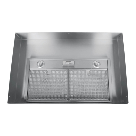
- Page 1 30", 36" and 48" Custom Hood Insert ZVC3OLSS ZVC36LSS ZVC48LSS Monogram° 49-80415 I 12-06 JR...
- Page 2 Installation Instructions BEFOREYOU BEGIN WARNING:To REDUCE THE RIsK OF FIRE,ELECTRIC SHOCKOR INJURYTO Read these instructions completelg carefullg. PERSONS, OBSERVE THE FOLLOWING: Usethis unit onlg in the manner intended by the PORTANT- • Save these instructions for local manufacturer. If you have questions,contact the manufacturer.
- Page 3 Installation Instructions AVERTISSEMENT : AFIN AVERTISSEMENT REDUIRELERISQUED'INCENDIE,DECHOCS REDUIRE LE,RISQUE D'UNFEUDEFRITURE SUR :AFIN DE LA CUISINIERE : ELECTRIQUES O U DE BLESSURES CORPORELLES, VEUILLEZ VOUSCONFORMER AU× RECOMMANDATIONS A. Ne laissezjamaissanssurveillanceles6bments de cuissonde SUIVANTES : votre cuisini_re Iorsqu'ils sont r6gl6s_ une temperature6levee. A.
-
Page 4: Table Of Contents
Design Information CONTENTS Installation Instructions Design Information Product Clearances ................Step 1, Install Hood Liner ............Product Dimensions ..............Step 2, Connect Electrical ............Advance Planning Step 3, Install Insert Sleeve ............Advance Planning ................Step 4, Install Damper Plate ............Remote Mounting of the Control (Wired) ...... -
Page 5: Product Dimensions
Design Information PRODUCT DIMENSIONS ZVC30 Dimensions and Specifications (in inches) Outside Dimensions 27-1/2_ The Insert Sleeve The custom canopg must be sized to fit the insert sleeve. Construct the canopg with an opening that is: 26"W x 13-3116"D The opening must be constructed of 3/4"... - Page 6 Design Information PRODUCT DIMENSIONS ZVC36 Dimensions and Specifications (in inches) Outside Dimensions 27-1/2" The Insert Sleeve The custom canopg must be sized to fit the insert 16-3/4" sleeve. Construct the canopg with an opening that is: 26"W x 13-3116"D The opening must be constructed of 3/4"...
-
Page 7: Product Dimensions
Design Information PRODUCT DIMENSIONS ZVC48 Dimensions and Specifications (in inches) Outside Dimensions I" 39-1/2" © © © The Insert Sleeve The custom canopy must be sized to fit the insert sleeve. Construct the canopy with an opening 29-1/2" that is: 38-3/4"W x 13-3/16"D The opening must be constructed... -
Page 8: Advance Planning
Advance Planning ADVANCE PLANNING POWER SUPPLY IMPORTANT - (Please read carefully) Ductwork Planning • This hood is equipped for 8" round ductwork. • Determine the exact locution of the vent hood, WARNING: FOR PERSONAL SAFETY,THIS APPLIANCE • Plan the route for venting exhaust to the outdoors, MUST BE PROPERLYGROUNDED. -
Page 9: Duct Fittings
3-1/4" x 10" wall cap duct fitting equivalent. Equivalent w/damper 24 ft. length of duct pieces are based round roof vent on actual tests conducted by GE Evaluation Engineering and reflect Total Duct Run. requirements for good venting performance with any ventilation hood. -
Page 10: Installation Preparation
Installation Preparation TOOLS AND MATERIALS REQUIRED 1/4" pivoting (NOT SUPPLIED) soo et 1" conduit (for remote mounting only) Needle-nose pliers Electric drill and Aluminized 3/8" socket/ appropriate bits duct tape nut driver Silicone Wire nuts 8" ducting and Pencil and tape measure Safety glasses caps as needed "_... -
Page 11: Parts Provided
4 insert sleeve blower motor washers REMOTE MOUNTING OF THE CONTROL (WIRED) Blower motor (Models ZVC30LSS and ZVC36LSS) Control wall bracket Blanking plate for remote control opening* *NOTE:To be used on custom hood when controls are Control Control remotely mounted. -
Page 12: Ductwork, Wiring Locations
Wall Installation Preparation 5-1/2" from DUCTWORK, WIRING LOCATIONS rear wall to Determine the exact location of the insert centerline sleeve. Mark the exact centerline location. The ceiling structure must be capable of supporting the weight of the insert sleeve (appro×imatelg 100 pounds) and ang inadvertent user contact loads, •... -
Page 13: Construct Ceiling Support
Island Installation Preparation CONSTRUCT CEILING SUPPORT (for Island Installation) Plan the Location of the Hood and Ductwork The insert sleeve in the ceiling must be centered left The ceiling structure must be capable of supporting to right over the cooktop, weight of the insert sleeve (approximatelu !00 pounds) and anu inadvertent... -
Page 14: Remote Mounting Of The Control (Wired)
Preparation Installation REMOTE MOUNTING OF THE CONTROL REMOTE LOCATION FOR CONTROL (WIRED} The control can be removed from the hood and installed in a backsplash or countertop. -- IL WARNING: Disconnect electrical • A cover plate is provided to cover the opening in power from unit before beginning remote control the hood when the control is removed. - Page 15 Preparation Installation REMOTE MOUNTING OF THE CONTROL (WIRED) {CONT.) WALL MOUNT COUNTERTOP Mounting Control Wall Control bracket bracket ¼ Jack • _"-"r"--..Co nne cto r 4-wire cordi-._" Mounting plate Screws, __ord Screws 4,-_ Mounting bracket _ Apply silicone around plate I.
-
Page 16: Installation Instructions
Installation Instructions [STEP I] INSTALL HOOD LINER 1. Frame the cutout opening to fit the linen NOTE: The opening support must be 3/4" thick 3. Secure the liner to the cabinet with 6 screws wood to accept the liner installation screws. -
Page 17: Step 2, Connect Electrical
Installation Instructions [STEP 2] CONNECT ELECTRICAL Verifg that power is turned off at the source. WARNING: ,f house wiring is not 00000 2-wirewith a ground wire, an electrician will need to convertexisting w iringto meet these specs. When house wiringis aluminum, be sureto use U.L approved anti-oxidant c ompound and aluminum-to-copper connectors. -
Page 18: Step 3, Install Insert Sleeve
Installation Instructions ISTEP 31 INSTALL INSERT SLEEVE 1. Tuck the house wiring out of the wag. 2, Install the insert sleeve into the cutout opening of custom cabinet frame. 4. Align 8" duct to exhaust opening of insert sleeve and seal with aluminum tape. -
Page 19: Step 4, Install Damper Plate
Installation Instructions [STEP 4] INSTALL DAMPER PLATE 1. Pick up damper plate assemblg and rotate so that ° vent side is up and bracket is located on left as gou 3. Secure damper plate assemblg bg placing nuts stand facing hood. on bolts and tightening with socket or wrench. -
Page 20: Step 5, Install Blower Motor
Installation Instructions ISTEP sl INSTALL BLOWER MOTOR iioooooii 3. Place blower motor on damper plate assemblg 1. Pick up blower motor and rotate so tabs align bg sliding blower motor tabs into slots of damper with damper plate bracket. plate assemblg. 2. -
Page 21: Step 7, Install Filters
Installation Instructions ISTEP 7 ] INSTALL F ILTERS [STEP 8] FINALIZE INSTALLATION 1.Check to be sure all tape and packaging 1. Remove protective film from the filters. materials have been removed. 2. Refer to Owner's Manual for operating instructions. Clip 2. - Page 22 Notes...
- Page 23 Notes...
- Page 24 ® local service in your area, call 1.800.444.1845. Note: Product improvement is a continuing endeavor at General Electric. Therefore, materials, appearance and specifications are subject to change without notice. Monogram: GEConsumer&hldustrial GEAppliances GeneralElectricCompany Louisville, K Y40225 ge com Printed in Italg @2006 GECompany...