Honeywell 2020 User Manual
2d cordless imaging system
Hide thumbs
Also See for 2020:
- User manual (188 pages) ,
- User manual (192 pages) ,
- User manual (284 pages)
Table of Contents
Table of Contents

Related Manuals for Honeywell 2020


Summary of Contents for Honeywell 2020
- Page 1 2020/4820/4820i 2D Cordless Imaging System User’s Guide ™...
- Page 2 Disclaimer Honeywell International Inc. (“HII”) reserves the right to make changes in speci- fications and other information contained in this document without prior notice, and the reader should in all cases consult HII to determine whether any such changes have been made. The information in this publication does not repre- sent a commitment on the part of HII.
- Page 3 Caution: Any changes or modifications made to this equipment not expressly approved by Honeywell may void the FCC authorization to operate this equipment. Use only shielded data cables with this system. This unit has been tested with cables less than 3 meters.
- Page 4 5627 BT Eindhoven The Netherlands Honeywell shall not be liable for use of our product with equipment (i.e., power supplies, personal computers, etc.) that is not CE marked and does not comply with the Low Voltage Directive. This equipment is intended for...
- Page 5 If you need more information on the collection, reuse, and recycling systems, please contact your local or regional waste administration. You may also contact your supplier for more information on the environmental performances of this product. Germany If your product is marked with the GS symbol, then the product has been issued a GS certificate showing compliance to EN 60950-1, Second Edition.
- Page 6 Brazil (4820i, 2020-5 Scanner and AP-010BT) This product is approved by Anatel, according to the procedures regulated by Resolution No. 242/2000 and meets the technical requirements applied. Este produto está homologado pela ANATEL, de acordo com os procedimentos regulamentados pela Resolução No. 242/2000 e atende aos requisitos técnicos aplicados.
- Page 7 • Do not disassemble or modify batteries. Caution: Danger of explosion if batteries are incorrectly replaced. Replace only with the same or equivalent type recommended by the manufacturer. Dispose of used batteries according to the recycle program for batteries as directed by the governing agency for the country where the batteries are to be discarded.
- Page 8 Required Safety Labels Scanner Compliance Label locations Item Number, Serial Number and Revision Information location...
- Page 9 Base Compliance Label locations Item Number, Serial Number and Revision Information location...
-
Page 11: Table Of Contents
Table of Contents Chapter 1 - Getting Started About This Manual ............1-1 Unpacking the System ..........1-1 Image Scanner Models ..........1-1 Cordless System: Main Components ......1-2 About the Battery ............1-2 Proper Disposal of the Battery ........1-3 Connecting the Base ........... - Page 12 Data Accumulation Mode On ....3-2 Base Charge Mode ............. 3-3 Beeper and LED Sequences and Meaning ....3-4 Image Scanner LED Sequences and Meaning ..3-4 2020 LED Sequences and Meaning ..... 3-4 Image Scanner Modes..........3-5 Unlinking the Image Scanner ........ 3-5...
- Page 13 Single Image Scanner Operation ........ 3-5 Locked Link Mode - Single Image Scanner ..3-6 Open Link Mode - Single Image Scanner .... 3-6 Override Locked Image Scanner ......3-6 Multiple Image Scanner Operation......3-7 Image Scanner Name ..........3-7 Image Scanner Report ..........
- Page 14 Chapter 4 - Output Good Read Indicators..........4-1 Beeper – Good Read ..........4-1 Beeper Volume – Good Read ....... 4-1 Beeper Pitch – Good Read ........4-2 Beeper Duration – Good Read ......4-2 LED – Good Read ..........4-2 Number of Beeps –...
- Page 15 Video Reverse............4-22 Working Orientation ..........4-22 Chapter 5 - Data Editing Prefix/Suffix Overview ..........5-1 To Add a Prefix or Suffix: ........5-1 To Clear One or All Prefixes or Suffixes: ....5-2 To Add a Carriage Return Suffix to All Symbologies ..........
- Page 16 Code 39 ............... 7-5 Code 32 Pharmaceutical (PARAF) ....... 7-7 Full ASCII .............. 7-8 Code 39 Code Page ..........7-8 Interleaved 2 of 5 ............7-9 Code 93 ..............7-11 Code 93 Code Page ........... 7-11 Straight 2 of 5 Industrial (three-bar start/stop) ... 7-12 Straight 2 of 5 IATA (two-bar start/stop) ....
- Page 17 TCIF Linked Code 39 (TLC39) ........7-39 Postal Codes ............. 7-39 Intelligent Mail Bar Code ........7-39 ID-tag (UPU 4-State) .......... 7-40 Postnet ............... 7-40 Planet Code ............7-41 British Post ............7-42 Canadian Post ............ 7-42 Kix (Netherlands) Post ........7-42 Australian Post ...........
- Page 18 SEMI Font..............9-3 OCR Templates ............9-3 Creating an OCR Template ........9-3 Stringing Together Multiple Formats (Creating “Or” Statements) ......9-5 OCR User-Defined Variables........9-6 Reading Multi-Row OCR ........9-7 OCR Check Character..........9-7 OCR Modulo 10 Check Character ......9-8 OCR Modulo 36 Check Character ......9-8 OCR User-Defined Check Character......9-8 Weighting Options ..........
- Page 19 Imaging Default Commands......12-27 OCR Selections..........12-29 Minimizing Bluetooth/ISM Band Network Activity ........... 12-30 Chapter 13 - Product Specifications 4820 Product Specifications........13-1 4820i Product Specifications ........13-3 2020-5 Product Specifications ........13-4 Chapter 14 - Maintenance Repairs ..............14-1...
- Page 20 Maintenance ..............14-1 Cleaning the Device ..........14-1 Inspecting Cords and Connectors ...... 14-1 Replacing the 2020 Interface Cable: ....14-2 Assembling the Battery Charge Sleeve Kit....14-3 Troubleshooting the Base..........14-4 Troubleshooting the Image Scanner......14-4 Chapter 15 - Customer Support Product Service and Repair........15-1 Online Product Service and Repair Assistance ..
-
Page 21: Chapter 1 - Getting Started
4820/4820i. Product specifications, dimensions, warranty, and customer sup- port information are also included. Honeywell bar code image scanners are factory programmed for the most com- mon terminal and communications settings. If you need to change these set- tings, programming is accomplished by scanning the bar codes in this guide. -
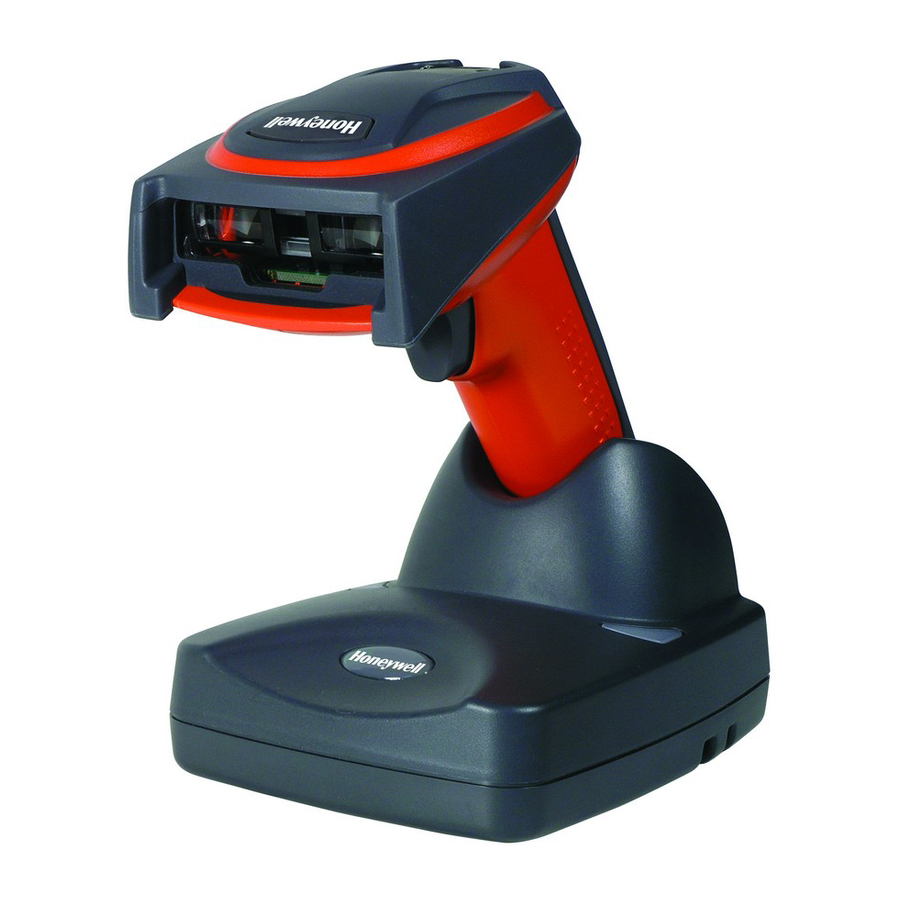
Page 22: Cordless System: Main Components
Charging Information The battery is designed to charge while the image scanner is positioned in the cordless base unit. Refer to "2020 LED Sequences and Meaning" on page 3-4 for an interpretation of the Charge Status indicators. • Place the image scanner in the base that is connected to an appropriate power supply. -
Page 23: Proper Disposal Of The Battery
Replace it after the battery is unable to hold an adequate charge. • If you are not sure if the battery or charger is working properly, send it to Honeywell International Inc. or an authorized service center for inspection. Refer to Customer Support on page 15-1 for additional information. -
Page 24: Connecting The Base With Keyboard Wedge
For additional USB programming and technical information, refer to the Honey- well “USB Application Note,” available at www.honeywell.com/aidc Connecting the Base with Keyboard Wedge 1. Turn off power and disconnect the keyboard cable from the back of the ter- minal/computer. - Page 25 2. Connect the appropriate interface cable to the base and to the terminal/ computer and keyboard. Make sure the cables are secured in the wireways in the bottom of the base and that the base sits flat on a horizontal surface. 3.
-
Page 26: Connecting The Base With Rs-232 Serial Port
4. Once the image scanner has been fully connected, power up the computer. Connecting the Base with RS-232 Wedge The 2020 uses TTL signal levels to wedge into an RS-232 serial network. Use only 2020 serial wedge cables to prevent damage to the base. Refer to... -
Page 27: Linking Image Scanner To Base
3. Connect the appropriate interface cable to the base. Make sure the cables are secured in the wireways in the bottom of the base and that the base sits flat on a horizontal surface. Note: For the base to work properly, you must have the correct cable for your type of computer. -
Page 28: Communication Between The Cordless System And The Host
At this point, you are set to one image scan- ner to one base. Image Scanner Green LED 2020 Base Red LED 1. Provide power to the base. 2. Place the image scanner into the base. The image scanner and base link. -
Page 29: Reading Techniques
When data is scanned, the data is sent to the host system via the base unit. The cordless image scanner recognizes data acknowledgement (ACK) from the base unit. If it cannot be determined that the data has been properly sent to the base, the image scanner issues an error indication. - Page 30 Linear bar code 2D Matrix symbol The aiming beam is smaller when the image scanner is closer to the code and larger when it is farther from the code. Symbologies with smaller bars or ele- ments (mil size) should be read closer to the unit. Symbologies with larger bars or elements (mil size) should be read farther from the unit.
-
Page 31: Chapter 2 - Programming The Interface
Programming the Interface Introduction Chapter 1 describes connecting the base to the computer with the appropriate interface cable. This chapter describes how to program your system for the desired interface. Programming the Interface - Plug and Play Plug and Play bar codes provide instant image scanner set up for commonly used interfaces. -
Page 32: Rs-232
RS-232 The RS-232 Interface bar code is used when connecting to the serial port of a PC or terminal. The following RS-232 Interface bar code also programs a car- riage return (CR) and a line feed (LF) suffix, baud rate, and data format as indi- cated below. -
Page 33: Ibm 4683 Ports 5B, 9B, And 17 Interface
IBM 4683 Ports 5B, 9B, and 17 Interface Scan one of the following “Plug and Play” codes to program the image scanner for IBM 4683 Port 5B, 9B, or 17. Note: After scanning one of these codes, you must power cycle the cash register. -
Page 34: Ibm Surepos
IBM SurePos Scan one of the following “Plug and Play” codes to program the image scanner for IBM SurePos (USB Handheld image scanner) or IBM SurePos (USB Table- top imager). Note: After scanning one of these codes, you must power cycle the cash register. -
Page 35: Usb Pc Or Macintosh Keyboard
Scan the following code to program the image scanner to emulate a regular RS- 232-based COM Port. If you are using a Microsoft® Windows® PC, you will need to download a driver from the Honeywell website (www.honeywell.com/ aidc). The driver will use the next available COM Port number. Apple® Macin- tosh computers recognize the image scanner as a USB CDC class device and automatically uses a class driver. -
Page 36: Serial Wedge
CTS/RTS Emulation CTS/RTS Emulation On * CTS/RTS Emulation Off ACK/NAK Mode ACK/NAK Mode On * ACK/NAK Mode Off Serial Wedge To set up the serial wedge terminal ID, use the serial terminal ID 050 and follow the instructions on page 2-6. - Page 37 For example, an IBM AT terminal has a Terminal ID of 003. You would scan the Terminal ID bar code, then 0, 0, 3 from the Programming Chart inside the back cover of this manual, then Save. If you make an error while scanning the digits (before scanning Save), scan the Discard code on the Programming Chart,...
-
Page 38: Supported Terminals
Supported Terminals Terminal Terminal Model(s) 3496, 3497, 122 key 3496, 3497, 102 key VT510, 520, 525 (PC style) VT510, 520, 525 (DEC style LK411) Esprit 200, 400 Heath Zenith PC, AT 003 * Heath Zenith Vectra 003 * Vectra PS/2 25, 30, 77DX2 AT, PS/2 30–286, 50, 55SX, 60, 003 * 70, 70–061, 70–121, 80... - Page 39 Wand Emulation (Code 39 Format) Wand Emulation (Same Code Format) * Default for 2020-5B and 2020-5BE models **It is best to use the Plug and Play bar codes, beginning on page 2-1 to program these interfaces, rather than scanning the terminal ID listed in this table.
-
Page 40: Keyboard Country
Keyboard Country Scan the appropriate country code below to program the keyboard for your country. As a general rule, the following characters are supported, but need special care for countries other than the United States: @ | $ # { } [ ] = / ‘ \ < > ~ * United States Belgium Brazil... - Page 41 Keyboard Country (continued) Italy Latin America Netherlands (Dutch) Norway Poland Portugal Romania Russia Slovakia Spain Sweden Switzerland (German) 2 - 11...
-
Page 42: Keyboard Style
Keyboard Country (continued) Turkey F Turkey Q U.K. Keyboard Style This programs keyboard styles, such as Caps Lock and Shift Lock. Default = Regular. Regular is used when you normally have the Caps Lock key off. * Regular Caps Lock is used when you normally have the Caps Lock key on. Caps Lock Shift Lock is used when you normally have the Shift Lock key on (not common to U.S. -
Page 43: Keyboard Function Relationships
Autocaps via NumLock bar code should be scanned in countries (e.g., Ger- many, France) where the Caps Lock key cannot be used to toggle Caps Lock. The NumLock option works similarly to the regular Autocaps, but uses the Num- Lock key to retrieve the current state of the Caps Lock. Autocaps via NumLock Emulate External Keyboard should be scanned if you do not have an external keyboard (IBM AT or equivalent). - Page 44 Turbo Mode: The image scanner sends characters to a terminal faster. If the terminal drops characters, do not use Turbo Mode. Default = Off Turbo Mode On * Turbo Mode Off Numeric Keypad Mode: Sends numeric characters as if entered from a numeric keypad.
-
Page 45: Rs-232 Baud Rate
RS-232 Baud Rate Baud Rate sends the data from the image scanner to the terminal at the speci- fied rate. The host terminal must be set for the same baud rate as the image scanner. Default = 115,200. 1200 2400 4800 9600 19200... -
Page 46: Rs-232 Receiver Time-Out
Parity provides a means of checking character bit patterns for validity. Default = None. 7 Data, 1 Stop, Parity Even 7 Data, 1 Stop, Parity None 7 Data, 1 Stop, Parity Odd 7 Data, 2 Stop, Parity Even 7 Data, 2 Stop Parity None 7 Data, 2 Stop, Parity Odd 8 Data, 1 Stop, Parity Even * 8 Data, 1 Stop, Parity None... -
Page 47: Rs-232 Handshaking
RS-232 Handshaking RS-232 Handshaking allows control of data transmission from the image scan- ner using software commands from the host device. CTS/RTS operates in mode 2. When this feature is turned Off, no data flow control is used. When Data Flow Control is turned On, the host device suspends transmission by sending the XOFF character (DC3, hex 13) to the image scanner. - Page 48 Escape commands are addressed to the image scanner via “Application Work Groups.” Once a command is sent, all image scanners in a group respond to that command. Because of this situation, it is recommended that each image scanner is assigned to its own group in Host ACK mode. The commands to which the image scanner responds are listed on page 2-20.
-
Page 49: Host Ack Enable
Host ACK Enable Host ACK On * Host ACK Off 2 - 19... -
Page 50: Wand Emulation
2020 Host Escape Commands Command Actiona Double beeps to indicate a successful menu change was made. b Triple beeps to indicate a menu change was unsuccessful. 1 The green LED illuminates for 135 milliseconds followed by a pause. -
Page 51: Wand Emulation Data Block Size
The Same Code Format transmits U.P.C., EAN, Code 128 and Interleaved 2 of 5 without any changes, but converts all other symbologies to Code 39. 2D sym- bologies are converted to Code 128. The Code 39 Format bar code below sets the terminal ID to 61, and the Same Code Format bar code sets the terminal ID to 64. -
Page 52: Wand Emulation Delay Between Blocks
Wand Emulation Delay Between Blocks This sets the delay time between data blocks. Default = 50ms. * 50ms 150ms 500ms Wand Emulation Overall Checksum When this option is turned on, a computed check character is added at the end of the entire message. The check character is the character which when Exclu- sive-OR’d with every preceding character of the message yields a result of 0x00 (00H). -
Page 53: Wand Emulation Transmission Rate
Wand Emulation Transmission Rate The Transmission Rate is limited by the terminal’s ability to receive data without dropping characters. Default = 25 inches/second. * 25 Wand Emulation Polarity The Polarity can be sent as standard with black bars high, or reversed with white spaces high. -
Page 54: Wand Emulation Idle
Wand Emulation Idle The idle describes the state of the image scanner when no data is being trans- mitted. When in Wand Emulation mode, you must set the image scanner’s idle state to match the idle state for the device to which the image scanner is con- nected. -
Page 55: Chapter 3 - Basic System Operation
Basic System Operation Cordless Base The cordless base provides the link between the cordless image scanner and the host system. The base contains an interface assembly and an RF commu- nication module. The RF communication module performs the data exchange between the cordless image scanner and the interface assembly. -
Page 56: System Conditions
System Conditions The components of the cordless system interact in specific ways as you associ- ate an image scanner to a base, as you move an image scanner out of range, bring an image scanner back in range, or swap image scanners between two cordless systems. -
Page 57: Base Charge Mode
Base Charge Mode In order for the battery to be charged, there must be enough voltage for the cir- cuitry to work. There are three methods during which power can be supplied to the base: 1:9VDC power supply connected to the barrel connector 2:12VDC host power source only 3:5VDC host power source only The chart below describes each selection by condition. -
Page 58: Beeper And Led Sequences And Meaning
30% to 80% charged Slow flash, 1 second on, 1 second off <30% charged Fast flash, 300 mSec on, 300 mSec off Note: Charging only occurs with external power applied to the 2020 or 12 volt host power. 3 - 4... -
Page 59: Image Scanner Modes
System Condition System Status Indicator (Red LED) Power On/System Idle LED is on Receiving Data (2020 only) Blink LED for short duration in multiple pulses. Occurs while transferring data to/from the RF module or the Host port. Base requests status from Blink LED once (occurs approx. -
Page 60: Locked Link Mode - Single Image Scanner
Locked Link Mode - Single Image Scanner If you link an image scanner to a base using the Locked Link Mode, other image scanners are blocked from being linked if they are inadvertently placed into the base. If you do place a different image scanner into the base, it will charge the image scanner, but the image scanner will not be linked. -
Page 61: Multiple Image Scanner Operation
Multiple Image Scanner Operation Note: Multiple Image Scanner Operation Mode allows you to link up to 7 image scanners to one base. You cannot join an 8th image scanner until you unlink one of the 7 image scanners or take an image scanner out of range. - Page 62 To rename image scanners with sequential, numeric names, scan the bar codes below. Scan the Reset code after each name change and wait for the scanner to re-link to the base before scanning another bar code to rename the next image scanner. 0001 0002 0003...
-
Page 63: Image Scanner Report
You may use Bar Code Builder, which is included with QuickView. Refer to QuickView on page 11-6 for instructions about downloading QuickView from the Honeywell website: www.honeywell.com/aidc Image Scanner Report Scan the bar code below to generate a report for the connected image scan- ners. -
Page 64: Application Work Group Selection
Application Work Group Selection This programming selection allows you to assign an image scanner to a work group by scanning the bar code below. You may then program the settings (e.g., beeper volume, prefix/suffix, data formatter) that your application requires. Default = Group 0. -
Page 65: Resetting The Standard Product Default Settings: All Application Work Groups
Resetting the Standard Product Default Settings: All Application Work Groups The following bar code defaults all of the work groups to the factory settings. Standard Product Default Settings: All Application Groups Menu Commands, beginning on page 12-5 list the standard product default settings for each of the commands (indicated by an asterisk (*) on the program- ming pages). -
Page 66: Using The Image Scanner With Bluetooth Devices
If you go out of range with your image scanner, the image scanner will not reconnect to the Bluetooth device when it is back in range. If you want to re-link to the 2020 base, refer to "Override Locked Image Scanner"... - Page 67 2. Tap the Start flag at the top left of the Today screen. 3. Select Settings at the bottom of the menu. 3 - 13...
- Page 68 4. Tap the Connections tab at the bottom of the screen and then tap the Radio Manager icon. 5. Enable one of the Bluetooth modes (e.g., Bluetooth only or 80211b/ Bluetooth). The screen below shows that only the GSM radio is active. 3 - 14...
- Page 69 6. Tap Bluetooth Only and Apply. The status changes to Success. 7. Tap OK in the top right of the screen and tap X on the upper, right corner to return to the Today screen. The Bluetooth icon displays in the bottom, right part of the screen.
- Page 70 9. Select Advanced Features -> Bluetooth Devices. Note: If you have already used Bluetooth and changed any of the default settings, you may want to first select My Bluetooth device and ensure that it is connectable and the Bluetooth com port is enabled. 10.
- Page 71 11. Tap Next on the Bluetooth Device Discovery Wizard. 12. Keep the default radio button selection of Any Bluetooth device and select Next. The Mobility Systems device searches for other Bluetooth devices. If the 4820i is in BTConnection - PDA Mobility Systems Mode (see Connection - PDA/Mobility Systems Device on page 3-12), it will appear in the device discovery window.
-
Page 72: Changing The Image Scanner's Bluetooth Pin Code
13. Select the 4820i by checking the box and select Next and Finish. 14. Select Next and Finish. 15. Select the X to return to the desktop. Changing the Image Scanner’s Bluetooth PIN Code Some devices require a PIN code as part of the Bluetooth security features. Your image scanner’s default PIN is 1234, which you may need to enter the first time you connect to your PDA or PC. - Page 73 characters. To change the PIN, scan the bar code below and then scan the appropriate numeric bar codes from the Programming Chart inside the back cover of this manual. Scan Save to save your selection. Bluetooth PIN When authentication is enabled on the Mobility Systems device, you must enter the PIN of the image scanner.
-
Page 74: Starting Scanwedge
Once the image scanner is linked to the Mobility Systems device, you need to configure ScanWedge for the correct COM port and then start ScanWedge. For additional information, refer to the Honeywell Powertools User’s Guide, which can be downloaded from www.honeywell.com/aidc. -
Page 75: Alarm Sound Type
and then set the time-out duration (from 0-3000 seconds) by scanning digits on Programming Chart inside the back cover, then scanning Save. Default = 0 sec (no alarm). Base Alarm Duration Image Scanner Alarm Duration Note: If you are out of range when you scan a bar code, you will receive an error beep even if you do not have the alarm set. -
Page 76: Data Accumulation Mode
Data Accumulation Mode Note: Data Accumulation mode has limitations when using multiple scanners to one base. If a cordless system is being used in "multiple link mode" where up to 7 scanners are to be connected to one base, some accumulated or batched scans could be lost if scanners are constantly being moved in and out of range. -
Page 77: Batch Mode Transmit Delay
Batch Mode Transmit Delay Sometimes when accumulated scans are sent to the host system, the transmis- sion of those scans is too fast for the application to process. To program a transmit delay between accumulated scans, scan one of the following delays. Default = Off. - Page 78 3 - 24...
-
Page 79: Good Read Indicators
Output Good Read Indicators Beeper – Good Read The beeper may be programmed On or Off in response to a good read. Turning this option off, only turns off the beeper response to a good read indication. All error and menu beeps are still audible. Default = On. * Beeper - Good Read On Beeper - Good Read Off Beeper Volume –... -
Page 80: Beeper Pitch - Good Read
Beeper Pitch – Good Read The beeper pitch codes modify the pitch (frequency) of the beep the image scanner emits on a good read. Default = Medium. Low (1600 Hz) * Medium (3250 Hz) High (4200 Hz) Beeper Duration – Good Read The beeper duration codes modify the length of the beep the image scanner emits on a good read. -
Page 81: Good Read Delay
scan the bar code below and then scan a digit (1-9) bar code and the Save bar code on the Programming Chart inside the back cover of this manual. Default = Number of Beeps/LED Flashes Good Read Delay This sets the minimum amount of time before the image scanner can read another bar code. -
Page 82: Serial Trigger Modes
Serial Trigger Modes Manual/Serial Trigger, Low Power You can activate the image scanner either by pressing the trigger, or using a serial trigger command (see Trigger Commands on page 12-4). When in manual trigger mode, the image scanner scans until a bar code is read, or until the trigger is released. - Page 83 Whenever the trigger is enabled, the timer is reset. If the image scanner is placed in the 2020 cradle and the battery is in the process of being charged, the image scanner will not go into power down mode. Default = 3600 seconds.
-
Page 84: Scan Stand Mode
Scan Stand Mode When a unit is in Scan Stand mode, it remains idle as long as it sees the Scan Stand symbol, below. When a different code is presented, the image scanner is triggered to read the new code. Note: The image scanner automatically adjusts the illumination LEDs to the lowest light level possible to maintain a good lock on the Scan Stand symbol. -
Page 85: Presentation Mode
Presentation Mode Scanning the bar code below programs the image scanner to work in Presentation Mode. Presentation Mode uses ambient light to detect bar codes. The LEDs are off until a bar code is presented to the image scanner, then the LEDs turn on automatically to read the code. -
Page 86: Presentation Sensitivity
Presentation Sensitivity Presentation Sensitivity is a numeric range that increases or decreases the image scanner's reaction time to bar code presentation. To set the sensitivity, scan the Sensitivity bar code, then scan the degree of sensitivity (from 0-20) from the inside back cover, and Save. 0 is the most sensitive setting, and 20 is the least sensitive. -
Page 87: Image Snap And Ship
Image Snap and Ship Image Snap and Ship tells the imager to take a picture (rather than read a bar code) when the trigger is pressed. Once the picture is snapped, it is shipped to the host system as a jpeg file by default. To revert to bar code reading, you must change to a different trigger mode (see Serial Trigger Modes beginning on... -
Page 88: User-Specified Reread Delay
Use shorter delays in applications where repetitive bar code scanning is required. Reread Delay only works when in Presentation Mode (see page 4-7). Default = Medium. Short (500 ms) * Medium (750 ms) Long (1000 ms) Extra Long (2000 ms) Extra Long (2000 ms) User-Specified Reread Delay If you want to set your own length for the reread delay, scan the bar code below,... -
Page 89: Illumination Lights
If you have an aimer delay programmed (see Aimer Delay on page 4-12), the aimer will be at 100% power during the delay, regardless of the LED Power Level. Note: If you scan the Off bar code, both the aimer and illumination lights turn off, making it impossible to scan bar codes in low light. -
Page 90: Aimer Delay
Aimer Delay The aimer delay allows a delay time for the operator to aim the image scanner before the picture is taken. Use these codes to set the time between when the trigger is pulled and when the picture is taken. During the delay time, the aiming light will appear, but the LEDs won’t turn on until the delay time is over. -
Page 91: Centering
Centering Use Centering to narrow the image scanner’s field of view to make sure the image scanner reads only those bar codes intended by the user. For instance, if multiple codes are placed closely together, centering will insure that only the desired codes are read. -
Page 92: Decode Search Mode
Scan Centering On, then scan one of the following bar codes to change the top, bottom, left, or right of the centering window. Then scan the percent you want to shift the centering window using digits on the inside back cover of this manual. -
Page 93: Preferred Symbology
Quick Omnidirectional - This is an abbreviated search for bar code features around the center region of an image. This mode quickly reads all symbologies in any orientation. The Quick Omnidirectional mode may miss some off-center symbols, as well as larger Data Matrix and QR Code symbols. Quick Omnidirectional Preferred Symbology Note: This selection does not apply to OCR. -
Page 94: Symbology Chart
High Priority Symbology To specify the high priority symbology, scan the High Priority Symbology bar code below. On the Symbology Chart on page A-1, find the symbology you want to set as high priority. Locate the Hex value for that symbology and scan the 2 digit hex value from the Programming Chart (inside back cover). -
Page 95: Output Sequence Overview
Output Sequence Overview Require Output Sequence When turned off, the bar code data will be output to the host as the image scanner decodes it. When turned on, all output data must conform to an edited sequence or the image scanner will not transmit the output data to the host device. - Page 96 • Discard This exits without saving any Output Sequence changes. Output Sequence Example In this example, you are scanning Code 93, Code 128, and Code 39 bar codes, but you want the image scanner to output Code 39 1st, Code 128 2nd, and Code 93 3rd, as shown below.
-
Page 97: Output Sequence Editor
To program the previous example using specific lengths, you would have to count any programmed prefixes, suffixes, or formatted characters as part of the length. If you use the example on page 4-18, but assume asuffix and specific code lengths, you would use the following command line: SEQBLK62001241FF6A001342FF69001243FF The breakdown of the command line is shown below: SEQBLK sequence editor start command... -
Page 98: Multiple Symbols
When the output sequence is Off , the bar code data is output to the host as the image scanner decodes it. Default = Off. Note: This selection is unavailable when the Multiple Symbols Selection is turned on. Required On/Not Required *Off Multiple Symbols When this programming selection is turned On, it allows you to read multiple... -
Page 99: No Read
No Read With No Read turned On, the image scanner notifies you if a code cannot be read. If using a QuickView Scan Data Window, an “NR” appears when a code cannot be read. If No Read is turned Off, the “NR” will not appear. Default = Off. -
Page 100: Video Reverse
Video Reverse Video Reverse is used to allow the image scanner to read bar codes that are inverted. The Off bar code below is an example of this type of bar code. If additional menuing is required, Video Reverse must be disabled to read the menu bar codes and then re-enabled after menuing is completed. - Page 101 * Upright Rotate Code Clockwise 90° (Rotate Image Scanner Counterclockwise) Upside Down Rotate Code Counterclockwise 90° (Rotate Image Scanner Clockwise) 4 - 23...
- Page 102 4 - 24...
-
Page 103: Chapter 5 - Data Editing
Data Editing Prefix/Suffix Overview When a bar code is scanned, additional information is sent to the host computer along with the bar code data. This group of bar code data and additional, user-defined data is called a “message string.” The selections in this section are used to build the user-defined data into the message string. -
Page 104: To Clear One Or All Prefixes Or Suffixes
which you want to apply the prefix or suffix. For example, for Code 128, Code ID is “j” and Hex ID is “6A”. Step 3. Scan the 2 hex digits from the Programming Chart inside the back cover of this manual or scan 9, 9 for all symbologies. Step 4. -
Page 105: To Add A Carriage Return Suffix To All Symbologies
Step 1. Scan the Clear One Prefix or Clear One Suffix symbol. Step 2. Determine the 2 digit Hex value from the Symbology Chart (included in Symbology Chart, beginning on page A-1) for the symbology from which you want to clear the prefix or suffix. Step 3. -
Page 106: Prefix Selections
Prefix Selections Add Prefix Clear One Prefix Clear All Prefixes Suffix Selections Add Suffix Clear One Suffix Clear All Suffixes Function Code Transmit When this selection is enabled and function codes are contained within the scanned data, the image scanner transmits the function code to the terminal. Charts of these function codes are provided in Supported Interface Keys start-... -
Page 107: Intercharacter, Interfunction, And Intermessage Delays
Intercharacter, Interfunction, and Intermessage Delays Some terminals drop information (characters) if data comes through too quickly. Intercharacter, interfunction, and intermessage delays slow the transmission of data, increasing data integrity. Each delay is composed of a 5 millisecond step. You can program up to 99 steps (of 5 ms each) for a range of 0-495 ms. -
Page 108: Interfunction Delay
Next, scan the Character to Trigger Delay bar code, then the 2-digit hex value for the ASCII character that will trigger the delay Code Page Mapping of Printed Bar Codes on page A-7. Delay Length Character to Trigger Delay To remove this delay, scan the Delay Length bar code, and set the number of steps to 0. -
Page 109: Intermessage Delay
Intermessage Delay An intermessage delay of up to 495 milliseconds may be placed between each scan transmission. Scan the Intermessage Delay bar code below, then scan the number of milliseconds and the Save bar code using the Programming Chart inside the back cover of this manual. 1st Scan Transmission 2nd Scan Transmission Intermessage Delay... - Page 110 5 - 8...
-
Page 111: Chapter 6 - Data Formatting
Data Formatting Data Format Editor Introduction You may use the Data Format Editor to change the image scanner’s output. For example, you can use the Data Format Editor to insert characters at certain points in bar code data as it is scanned. The selections in the following pages are used only if you wish to alter the output. -
Page 112: Other Programming Selections
Step 4. Code I.D. In the Symbology Chart, beginning on page A-1, find the symbology to which you want to apply the data format. Locate the Hex value for that symbology and scan the 2 digit hex value from the Programming Chart inside the back cover of this manual. - Page 113 F4 Send “xx” character “nn” times (Insert) leaving cursor in current cursor posi- tion. Syntax = F4xxnn (xx stands for the hex value for an ASCII code, see Code Page Mapping of Printed Bar Codes on page A-7, and nn is the numeric value (00-99) for the number of times it should be sent.) E9 Send all but the last “nn”...
- Page 114 characters to be replaced plus replacement characters; xx defines charac- ters to be replaced and xx defines replacement characters, continuing through zz and zz E5 Terminates character replacement. Syntax = E5. FE Compare character in current cursor position to the character “xx.” If char- acters are equal, increment cursor.
-
Page 115: Data Format Editor
Data Format Editor Enter Data Format * Default Data Format Clear One Data Format Clear All Data Formats Save Discard Data Formatter When Data Formatter is turned off, the bar code data is output to the host as read (including prefixes and suffixes). Choose one of the following options. Default = Data Formatter On, but Not Required. -
Page 116: Alternate Data Formats
Alternate Data Formats Alternate formats allow you “single shot” capability to scan one bar code using a different data format than your primary format. When data formats are pro- grammed (see page 6-1), you must input whether you are programming the pri- mary format, or an alternate format numbered 1, 2, or 3. - Page 117 Symbologies This programming section contains the following menu selections. Refer to Chapter 12 for settings and defaults. • All Symbologies • ID-tag (UPU 4-State) • Australian Post • Intelligent Mail Bar Code • Aztec Code • Interleaved 2 of 5 •...
-
Page 118: All Symbologies
All Symbologies If you want to decode all the symbologies allowable for your image scanner, scan the All Symbologies On code. If on the other hand, you want to decode only a particular symbology, scan All Symbologies Off followed by the On sym- bol for that particular symbology. -
Page 119: Codabar
CodabarCodabar * On Codabar Start/Stop Characters Start/Stop characters identify the leading and trailing ends of the bar code. You may either transmit, or not transmit Start/Stop characters. Default = Don’t Transmit . Transmit * Don’t Transmit Codabar Check Character Codabar check characters are created using different “modulos.”... -
Page 120: Codabar Concatenation
When Check Character is set to Validate, but Don’t Transmit , the unit will only read Codabar bar codes printed with a check character, but will not transmit the check character with the scanned data. * No Check Character Validate Modulo 16, but Don’t Transmit Validate Modulo 16 and Transmit... - Page 121 Codabar Message Length Scan the bar codes below to change the message length. Refer to Message Length Description (page 7-2) for additional information. Minimum and Maximum lengths = 2-60. Minimum Default = 4, Maximum Default = 60. Minimum Message Length Maximum Message Length Code 39 <...
- Page 122 Code 39 Check Character No Check Character indicates that the image scanner reads and transmits bar code data with or without a check character. When Check Character is set to Validate, but Don’t Transmit, the unit only reads Code 39 bar codes printed with a check character, but will not transmit the check character with the scanned data.
-
Page 123: Code 32 Pharmaceutical (Paraf)
the bar codes are read, deleting the first space from each. The image scanner transmits the appended data when it reads a Code 39 bar code that starts with a character other than a space. Default = Off. * Off Code 32 Pharmaceutical (PARAF) Code 32 Pharmaceutical is a form of the Code 39 symbology used by Italian pharmacies. -
Page 124: Full Ascii
Full ASCII If Full ASCII Code 39 decoding is enabled, certain character pairs within the bar code symbol will be interpreted as a single character. For example: $V will be decoded as the ASCII character SYN, and /C will be decoded as the ASCII character #. -
Page 125: Interleaved 2 Of 5
Mapping of Printed Bar Codes on page A-7), and scan the value and the Save bar code from the Programming Chart on the inside the back cover of this man- ual. The data characters should then appear properly. Code 39 Code Page Interleaved 2 of 5 <... - Page 126 When Check Digit is set to Validate and Transmit, the image scanner only reads Interleaved 2 of 5 bar codes printed with a check digit, and will transmit this digit at the end of the scanned data. Default = No Check Digit. * No Check Digit Validate, but Don’t Transmit Validate and Transmit...
-
Page 127: Code 93
Code 93 < Default All Code 93 Settings > Code 93 * On Code 93 Message Length Scan the bar codes below to change the message length. Refer to Message Length Description (page 7-2) for additional information. Minimum and Maximum lengths = 0-80. Minimum Default = 0, Maximum Default = 80. Minimum Message Length Maximum Message Length Code 93 Code Page... -
Page 128: Straight 2 Of 5 Industrial (Three-Bar Start/Stop)
Mapping of Printed Bar Codes on page A-7), and scan the value and the Save bar code from the Programming Chart on the inside the back cover of this man- ual. The data characters should then appear properly. Code 93 Code Page Straight 2 of 5 Industrial (three-bar start/stop)... -
Page 129: Straight 2 Of 5 Iata (Two-Bar Start/Stop)
Straight 2 of 5 IATA (two-bar start/stop)Straight 2 of 5 IATA * Off Straight 2 of 5 IATA Message Length Scan the bar codes below to change the message length. Refer to Message Length Description (page 7-2) for additional information. -
Page 130: Matrix 2 Of 5
Matrix 2 of 5Matrix 2 of 5 * Off Matrix 2 of 5 Message Length Scan the bar codes below to change the message length. Refer to Message Length Description (page 7-2) for additional information. Minimum and Maximum lengths = 1-80. -
Page 131: Code 11
Code 11Code 11 * Off Check Digits Required This option sets whether 1 or 2 check digits are required with Code 11 bar codes. Default = Two Check Digits. One Check Digit * Two Check Digits Code 11 Message Length Scan the bar codes below to change the message length. -
Page 132: Isbt 128 Concatenation
Code 128Code 128 * On ISBT 128 Concatenation In 1994 the International Society of Blood Transfusion (ISBT) ratified a standard for communicating critical blood information in a uniform manner. The use of ISBT formats requires a paid license. The ISBT 128 Application Specification describes 1) the critical data elements for labeling blood products, 2) the current recommendation to use Code 128 due to its high degree of security and its space-efficient design, 3) a variation of Code 128 that supports concatenation... -
Page 133: Code 128 Code Page
Code 128 Message Length Scan the bar codes below to change the message length. Refer to Message Length Description (page 7-2) for additional information. Minimum and Maximum lengths = 0-80. Minimum Default = 0, Maximum Default = 80. Minimum Message Length Maximum Message Length Code 128 Code Page Code pages define the mapping of character codes to characters. -
Page 134: Upc-A
Telepen * Off Telepen Output Using AIM Telepen Output, the image scanner reads symbols with start/stop pattern 1 and decodes them as standard full ASCII (start/stop pattern 1). When Original Telepen Output is selected, the image scanner reads symbols with start/stop pattern 1 and decodes them as compressed numeric with optional full ASCII (start/stop pattern 2). - Page 135 UPC-A * On UPC-A Check Digit This selection allows you to specify whether the check digit should be transmit- ted at the end of the scanned data or not. Default = On . * On UPC-A Number System The numeric system digit of a U.P.C. symbol is normally transmitted at the beginning of the scanned data, but the unit can be programmed so it will not transmit it.
- Page 136 UPC-A Addenda This selection adds 2 or 5 digits to the end of all scanned UPC-A data. Default = Off for both 2 Digit and 5 Digit Addenda. 2 Digit Addenda On * 2 Digit Addenda Off 5 Digit Addenda On * 5 Digit Addenda Off UPC-A Addenda Required When Required is scanned, the image scanner will only read UPC-A bar codes...
-
Page 137: Upc-A/Ean-13
UPC-A/EAN-13 with Extended Coupon Code Use the following codes to enable or disable UPC-A and EAN-13 with Extended Coupon Code. When left on the default setting (Off), the imager treats Coupon Codes and Extended Coupon Codes as single bar codes. If you scan the Allow Concatenation code, when the imager sees the coupon code and the extended coupon code in a single scan, it transmits both as sepa- rate symbologies. - Page 138 UPC-E0 Expand UPC-E Expand expands the UPC-E code to the 12 digit, UPC-A format. Default = Off. * Off UPC-E0 Addenda Required When Required is scanned, the image scanner will only read UPC-E bar codes that have addenda. Default = Not Required. Required * Not Required UPC-E0 Addenda Separator...
- Page 139 UPC-E0 Check Digit Check Digit specifies whether the check digit should be transmitted at the end of the scanned data or not. Default = On. * On UPC-E0 Number System The numeric system digit of a U.P.C. symbol is normally transmitted at the beginning of the scanned data, but the unit can be programmed so it will not transmit it.
-
Page 140: Upc-E1
UPC-E1 Most U.P.C. bar codes lead with the 0 number system. For these codes, use UPC-E0 (page 7-21). If you need to read codes that lead with the 1 number system, use the UPC-E1 On selection. Default = Off. UPC-E1 On * UPC-E1 Off EAN/JAN-13... - Page 141 EAN/JAN-13 Addenda This selection adds 2 or 5 digits to the end of all scanned EAN/JAN-13 data. Default = Off for both 2 Digit and 5 Digit Addenda. 2 Digit Addenda On * 2 Digit Addenda Off 5 Digit Addenda On * 5 Digit Addenda Off EAN/JAN-13 Addenda Required When Required is scanned, the image scanner will only read EAN/JAN-13 bar...
-
Page 142: Isbn Translate
ISBN Translate When On is scanned, EAN-13 Bookland symbols are translated into their equiv- alent ISBN number format. Default = Off. * Off EAN/JAN-8EAN/JAN-8 * On EAN/JAN-8 Check Digit This selection allows you to specify whether the check digit should be transmit- ted at the end of the scanned data or not. - Page 143 EAN/JAN-8 Addenda This selection adds 2 or 5 digits to the end of all scanned EAN/JAN-8 data. Default = Off for both 2 Digit and 5 Digit Addenda. 2 Digit Addenda On * 2 Digit Addenda Off 5 Digit Addenda On * 5 Digit Addenda Off EAN/JAN-8 Addenda Required When Required is scanned, the image scanner will only read EAN/JAN-8 bar...
-
Page 144: Msi
* Off MSI Check Character Different types of check characters are used with MSI bar codes. You can program the image scanner to read MSI bar codes with Type 10 check characters. Default = Validate Type 10, but Don’t Transmit. When Check Character is set to Validate Type 10 and Transmit, the image scanner will only read MSI bar codes printed with the specified type check character, and will transmit this character at the end of the scanned data. -
Page 145: Plessey Code
MSI Message Length Scan the bar codes below to change the message length. Refer to Message Length Description (page 7-2) for additional information. Minimum and Maximum lengths = 4-48. Minimum Default = 4, Maximum Default = 48. Minimum Message Length Maximum Message Length Plessey Code... -
Page 146: Gs1 Databar Omnidirectional
GS1 DataBar Omnidirectional < Default All GS1 DataBar Omnidirectional Settings > GS1 DataBar Omnidirectional * On GS1 DataBar Limited < Default All GS1 DataBar Limited Settings > GS1 DataBar Limited * On GS1 DataBar Expanded < Default All GS1 DataBar Expanded Settings > 7 - 30... -
Page 147: Posicode
GS1 DataBar Expanded * On GS1 DataBar Expanded Message Length Scan the bar codes below to change the message length. Refer to Message Length Description (page 7-2) for additional information. Minimum and Maximum lengths = 4-74. Minimum Default = 4, Maximum Default = 74. Minimum Message Length Maximum Message Length PosiCode... -
Page 148: Codablock F
PosiCode A and B * On You have to have PosiCode A and B on to read any of the PosiCode symbolo- gies. A and B On (No Limited) A and B and Limited A On (Limited B Off) * A and B and Limited B On (Limited A Off) PosiCode Message Length Scan the bar codes below to change the message length. -
Page 149: Code 16K
Codablock F * Off Codablock F Message Length Scan the bar codes below to change the message length. Refer to Message Length Description (page 7-2) for additional information. Minimum and Maximum lengths = 1-2048. Minimum Default = 1, Maximum Default = 2048. Minimum Message Length Maximum Message Length Code 16K... -
Page 150: Code 49
Code 16K * Off Code 16K Message Length Scan the bar codes below to change the message length. Refer to Message Length Description (page 7-2) for additional information. Minimum and Maximum lengths = 0-160. Minimum Default = 1, Maximum Default = 160. Minimum Message Length Maximum Message Length Code 49... - Page 151 Code 49 * On Code 49 Message Length Scan the bar codes below to change the message length. Refer to Message Length Description (page 7-2) for additional information. Minimum and Maximum lengths = 1-81. Minimum Default = 1, Maximum Default = 81. Minimum Message Length Maximum Message Length 7 - 35...
-
Page 152: Pdf417
PDF417 < Default All PDF417 Settings > PDF417 * On PDF417 Message Length Scan the bar codes below to change the message length. Refer to Message Length Description (page 7-2) for additional information. Minimum and Maximum lengths = 1-2750. Minimum Default = 1, Maximum Default = 2750. Minimum Message Length Maximum Message Length MicroPDF417... -
Page 153: Gs1 Composite Codes
MicroPDF417 * Off MicroPDF417 Message Length Scan the bar codes below to change the message length. Refer to Message Length Description (page 7-2) for additional information. Minimum and Maximum lengths = 1-366. Minimum Default = 1, Maximum Default = 366. Minimum Message Length Maximum Message Length GS1 Composite Codes... -
Page 154: Upc/Ean Version
UPC/EAN Version Scan the UPC/EAN Version On bar code to decode GS1 Composite symbols that have a U.P.C. or EAN linear component. (This does not affect GS1 Com- posite symbols with a GS1-128 or GS1 linear component.) UPC/EAN Version On * UPC/EAN Version Off GS1 Composite Code Message Length Scan the bar codes below to change the message length. -
Page 155: Tcif Linked Code 39 (Tlc39)
Default = GS1 Emulation Off . GS1-128 Emulation GS1 DataBar Emulation GS1 Code Expansion Off * GS1 Emulation Off TCIF Linked Code 39 (TLC39) This code is a composite code since it has a Code 39 linear component and a MicroPDF417 stacked code component. -
Page 156: Id-Tag (Upu 4-State)
ID-tag (UPU 4-State) * Off Postnet * Off Postnet Check Digit This selection allows you to specify whether the check digit should be transmit- ted at the end of the scanned data. Default = Don’t Transmit. Transmit Check Digit * Don’t Transmit Check Digit 7 - 40... -
Page 157: Planet Code
Planet Code * Off Planet Code Check Digit This selection allows you to specify whether the check digit should be transmit- ted at the end of the scanned data. Default = Don’t Transmit. Transmit Check Digit * Don’t Transmit Check Digit 7 - 41... -
Page 158: British Post
British Post * Off Canadian Post * Off Kix (Netherlands) Post Note: Kix code can misread when scanned sideways or upside down. Use Working Orientation, page 4-22, if your Kix codes will not usually be presented upright to the image scanner. * Off Australian Post * Off... - Page 159 Numeric N Table causes that field to be interpreted as numeric data using the N Table. Alphanumeric C Table causes the field to be interpreted as alphanumeric data using the C Table. Refer to the Australian Post Specification Tables. Default = Bar Output. * Bar Output Numeric N Table Alphanumeric C Table...
-
Page 160: Japanese Post
Japanese Post * Off China PostChina Post * Off China Post Message Length Scan the bar codes below to change the message length. Refer to Message Length Description (page 7-2) for additional information. Minimum and Maximum lengths = 2-80. -
Page 161: Korea Post
Korea PostKorea Post * Off Korea Post Message Length Scan the bar codes below to change the message length. Refer to Message Length Description (page 7-2) for additional information. Minimum and Maxi- mum lengths = 2-80. Minimum Default = 4, Maximum Default = 48. Minimum Message Length Maximum Message Length 7 - 45... -
Page 162: Qr Code
QR Code < Default All QR Code Settings > QR Code This selection applies to both QR Code and Micro QR Code. * On QR Code Message Length Scan the bar codes below to change the message length. Refer to Message Length Description (page 7-2) for additional information. -
Page 163: Data Matrix
Data Matrix < Default All Data Matrix Settings > Data Matrix * On Data Matrix Message Length Scan the bar codes below to change the message length. Refer to Message Length Description (page 7-2) for additional information. Minimum and Maximum lengths = 1-3116. Minimum Default = 1, Maximum Default = 3116. Minimum Message Length Maximum Message Length 7 - 47... -
Page 164: Maxicode
MaxiCode < Default All MaxiCode Settings > MaxiCode * On MaxiCode Message Length Scan the bar codes below to change the message length. Refer to Message Length Description (page 7-2) for additional information. Minimum and Maximum lengths = 1-150. Minimum Default = 1, Maximum Default = 150. Minimum Message Length Maximum Message Length 7 - 48... -
Page 165: Aztec Code
Aztec Code < Default All Aztec Code Settings > Aztec Code * On Aztec Code Message Length Scan the bar codes below to change the message length. Refer to Message Length Description (page 7-2) for additional information. Minimum and Maximum lengths = 1-3832. Minimum Default = 1, Maximum Default = 3832. Minimum Message Length Maximum Message Length Aztec Runes... -
Page 166: Chinese Sensible (Han Xin) Code
Chinese Sensible (Han Xin) Code < Default All Han Xin Settings > Han Xin Code * Off Han Xin Code Message Length Scan the bar codes below to change the message length. Refer to Message Length Description (page 7-2) for additional information. Minimum and Maximum lengths = 1-7833. -
Page 167: Chapter 8 - Imaging Commands
Imaging Commands The image scanner is like a digital camera in the way it captures, manipulates, and transfers images. The following commands allow you to alter the way the imager performs these functions. Single-Use Basis Imaging Commands with their modifiers send instructions to the imager on a single-use basis, and take effect for a single image capture. -
Page 168: Image Snap - Imgsnp
Step 1 - Take a Picture Using IMGSNP Image Snap - IMGSNP An image is taken whenever the hardware button is pressed, or when the Image Snap (IMGSNP) command is processed. The image snap command has many different modifiers that can be used to change the look of the image in memory. - Page 169 L - LED State Determines if the LEDs should be on or off, and when. Ambient illumination (0L) is preferred for taking pictures of color documents, such as ID cards, especially when the imager is in a stand. LED illumination (1L) is preferred when the imager is handheld.
- Page 170 G - Gain Gain is used in Manual Style only (2P). Like a volume control, the gain modifier boosts the signal and multiplies the pixel value. As you increase the gain, the noise in an image is also amplified. No gain (default) Medium gain Heavy gain Maximum gain...
-
Page 171: Image Ship - Imgshp
% - Target Set Point Percentage Sets the target point for the light and dark values in the captured image. A setting of 75% means 75% of the pixels are at or below the target white value, and 25% of the pixels are above the target white value. Altering this setting from the default is not recommended under normal circumstances. -
Page 172: Imgshp Modifiers
IMGSHP Modifiers A - Infinity Filter Enhances pictures taken from very long distances (greater than 10 feet or 3m). The Infinity Filter should not be used with IMGSHP Modifiers (page 8-6). Infinity filter off (default) Infinity filter on Example of Infinity Filter off (0A) Example of Infinity Filter on (1A) from approximately 12 feet from approximately 12 feet (3.66m) - Page 173 E - Edge Sharpen An edge sharpen filter cleans up the edges of an image, making it look cleaner and sharper. While edge sharpening does make the image look cleaner, it also removes some fine detail from the original image. The strength of the edge sharpen filter can be entered from 1 to 24.
- Page 174 H - Histogram Stretch Increases the contrast of the transmitted image. Not available with some image formats. No stretch (default) Histogram stretch Example of Histogram Stretch at 0H: Example of Histogram Stretch at 1H: I - Invert Image Invert image is used to rotate the image around the X or Y axis. Invert around the X axis (flips picture upside down) Invert around the Y axis (flips picture left to right) Example of image not...
- Page 175 IF- Noise Reduction Used to reduce the salt and pepper noise in an image. No salt and pepper noise reduction (default) Salt and pepper noise reduction Example of Noise Reduction Off Example of Noise Reduction On (0if): (1if): 8 - 9...
- Page 176 IR - Image Rotate Image as snapped (rightside up) (default) Rotate image 90 degrees to the right Rotate image 180 degrees (upside down) Rotate image 90 degrees to the left Example of Image Rotate set to Example of Image Rotate set to 2ir: 0ir: Example of Image Rotate set to...
- Page 177 K - Gamma Correction Gamma measures the brightness of midtone values produced by the image. You can brighten or darken an image using gamma correction. A higher gamma correction yields an overall brighter image. The lower the setting, the darker the image. The optimal setting for text images is 50K. Gamma correction off (default) Apply gamma correction for brightening typical document image Apply gamma correction factor n ( n = 0-1,000)
- Page 178 The bottom edge of the shipped image corresponds to row n - 1 of the image in memory. Range: 000 - 480. (Default = all rows) Uncropped Image: Example of Image Example of Image Crop set to 300R: Crop set to 300L: Example of Image Crop set to Example of Image Crop set to 200B:...
- Page 179 S - Pixel Ship Pixel Ship sizes an image in proportion to its original size. It decimates the image by shipping only certain, regularly spaced pixels. For example, 4S would transmit every fourth pixel from every fourth line. The smaller number of pixels shipped, the smaller the image, however, after a certain point the image becomes unusable.
- Page 180 This filter typically provides better JPEG compression than the standard E - Edge Sharpen command (see page 8-15). This filter also works well when shipping pure black and white images (1 bit per pixel). The optimal setting is 26U. Document image filter off (default) 26U Apply document image filter for typical document image Apply document image filter using grayscale threshold n.
-
Page 181: Image Size Compatibility
W - Histogram Ship A histogram gives a quick picture of the tonal range of an image, or key type. A low-key image has detail concentrated in the shadows; a high-key image has detail concentrated in the highlights; and an average-key image has detail concentrated in the midtones. - Page 182 2 of 5. Once one of these symbologies has been read, the image is retained for a possible IMGBOX command. The following IMGBOX example was executed and viewed using QuickView software. This software is available at www.honeywell.com/aidc. Click on Soft- ware Downloads. Select 4820 from the Products list, then select QuickView Software Utility.
-
Page 183: Imgbox Modifiers
IMGBOX Modifiers A - Output Image Width This option is used to size the image horizontally. If using this option, set the resolution (R) to zero. Example of Image Width set to 200A: Example of Image Width set to 600A: B - Output Image Height This option is used to size the image vertically. - Page 184 F - File Format This option indicates the type of file format in which to save the image. KIM format TIFF binary TIFF binary group 4, compressed TIFF grayscale Uncompressed Binary Uncompressed grayscale JPEG image (default) Outlined image BMP format H - Height of Signature Capture Area The height of the signature capture area must be measured in inches divided by .01.
- Page 185 R - Resolution of Signature Capture Area The resolution is the number of pixels that the imager outputs per each minimum bar width. The higher the value for R, the higher the quality of the image, but also the larger the file size. Values begin at 1000. The imager automatically inserts a decimal point between the first and second digit.
-
Page 186: Rf Default Imaging Device
X - Horizontal Bar Code Offset The horizontal bar code offset allows you to offset the horizontal center of the signature capture area. Positive values move the horizontal center to the right and negative values to the left. Measurements are in multiples of the minimum bar width. -
Page 187: Chapter 9 - Ocr Programming
OCR Programming Use this section to program the image scanner for optical character recognition (OCR). The image scanner reads 6 to 60 point OCR typeface. Note: OCR is not as secure as bar codes. To enhance security in OCR applications, create an OCR template to match the data and print an OCR check character. -
Page 188: U.s. Currency Font
OCR-B On allows you to scan characters in the OCR-B font. The default set- ting allows you to scan any eight digit combination. If you have created an OCR template, character combinations that fit the template can be scanned (see Creating an OCR Template, page 9-3). -
Page 189: Semi Font
SEMI Font SEMI Font On allows you to scan the SEMI font used in the semiconductor industry. SEMI Font On All OCR Off turns off all OCR capability in the image scanner, so the image scanner will be able to scan linear, stacked, matrix, and composite bar codes, but not OCR fonts. - Page 190 Template Characters represents any alphanumeric character (digit or letter) represents a check character position represents any digit represents any available OCR character represents character from user-defined variable “g” represents character from user-defined variable “h” represents character from user-defined variable “g” or “h” represents that a check character is verified but transmitted represents any uppercase letter marks the start of a new template...
-
Page 191: Stringing Together Multiple Formats (Creating "Or" Statements)
Character Match Sequences This method is used if you need a template that shows a specific character in a specific position. Put the character in uppercase in the template at the required position (template characters are always lower case). Example: You need to read three variable digits, three specific characters (ABC), followed by three variable digits. -
Page 192: Ocr User-Defined Variables
To create this template, you would enable the OCR-A font. Scan the Enter OCR Template symbol (page 9-13). Scan the d from the OCR Programming Chart in the back of this manual eight times, then scan the t to create the “or” statement. -
Page 193: Reading Multi-Row Ocr
Reading Multi-Row OCR The image scanner is capable of decoding multi-row OCR text. Note: Reading rows longer than sixteen characters is not recommended. Consider the following example. This example shows serial commands as they would be entered using QuickView. Example: You need to read multiple rows of OCR-A data as shown below: 12345678 ABCDEFGH First, enable the OCR-A font. -
Page 194: Ocr Modulo 10 Check Character
character. The image scanner transmits the OCR data without the check char- acter data. You must specify the location of the check character in the template with a c. Example: You need to read any combination of seven digits, with a modulo 10 check character in the eighth position. - Page 195 for the calculation. By default, the check character computation is unweighted, but the image scanner also supports two weighted modulo 10 checking schemes. Example: To program a modulo 11 check character, you would enter the following 11 characters in order: 0123456789X Also enter the OCR template: dddddddc...
-
Page 196: Weighting Options
Weighting Options By default, the check character computation is unweighted. It is possible to use one of two weighted modulo 10 schemes. Weighting is often used to detect if two neighboring characters are transposed, a common error when an operator keys in data. -
Page 197: Ocr Isbn Application Example
checking scheme used in MSI Code and in Code 32 Pharmaceutical (PARAF). To apply this weighting scheme, set the OCR check character to "0123456789x2x1" or scan the following symbol: 2-1-2-1 Weighted Modulo 10 Check Character Example: Scan the 2-1-2-1 Weighted Modulo 10 Check Character symbol. Also enter the OCR template: ddddddc Then scan the string below:... - Page 198 0123456789- 3. In Japan, it is common for two fields to follow the ISBN number, the three digit price field, and the four digit price field. The first field typically starts with a “C” (uppercase c), followed by four digits. The second field typically starts with a “P”...
-
Page 199: Ocr Template Codes
OCR Template Codes Note: Reading more than three rows of OCR is not recommended. Contact the factory if you have an application that requires reading four or more rows of OCR. † Enter OCR Template Enter User-Defined † Variable “g” Enter User-Defined †... - Page 200 9 - 14...
-
Page 201: Chapter 10 - Interface Keys
Interface Keys Keyboard Function Relationships The following Keyboard Function Code, Hex/ASCII Value, and Full ASCII “CTRL”+ relationships apply to all terminals that can be used with the image scanner. Refer to page 2-13 enable Control + ASCII mode. Function Code HEX/ASCII Value Full ASCII “CTRL”... - Page 202 The last five characters in the Full ASCII “CTRL”+ column ( [ \ ] 6 - ), apply to US only. The following chart indicates the equivalents of these five characters for different countries. Country Codes United States Belgium < Scandinavia <...
-
Page 203: Supported Interface Keys
Supported Interface Keys IBM AT/XT and PS/2 Compatibles, IBM XTs and IBM, DDC, Memorex WYSE PC/AT Compatibles Telex, Harris* ASCII Supported Keys Supported Keys Supported Keys Reserved Reserved Reserved Enter (KP) CR/Enter Enter Cap Lock Caps Lock ALT make Reserved ALT break Reserved CTRL make... - Page 204 Supported Interface Keys IBM, Memorex Telex (102)* Memorex Telex (88)** ASCII Supported Keys Supported Keys Reserved Reserved Enter Enter PF10 PF11 PF12 Reserved Reserved New Line New Line Field Forward Field Forward Reserved Tab/Field Forward Field Forward Delete Delete Field Exit New Line Insert Insert...
- Page 205 Supported Interface Keys Esprit 200, 400 Esprit 200, 400 Esprit 200, 400 ANSI ASCII ASCII Supported Keys Supported Keys Supported Keys Reserved Reserved Reserved New Line New Line New Line New Line New Line New Line Delete New Line New Line New Line Insert Escape...
- Page 206 Supported Interface Keys Apple Mac/iMac ASCII Supported Keys Reserved Enter/Numpad Enter CAPS ALT make ALT break CNTRL make CNTRL break RETURN APPLE make APPLE break RETURN Ins Help Home Prnt Scrn BACKSPACE LSHIFT TAB BACKSPACE 10 - 6...
-
Page 207: Chapter 11 - Utilities
Utilities To Add a Test Code I.D. Prefix to All Symbologies This selection allows you to turn on transmission of a Code I.D. before the decoded symbology. (See the Symbology Chart, beginning on page A-1) for the single character code that identifies each symbology.) This action first clears all current prefixes, then programs a Code I.D. -
Page 208: Show Scan Driver Revision
Show Scan Driver Revision Scan the bar code below to output the scan driver revision. The scan driver controls image capture. Show Scan Driver Revision Show Software Revision Scan the bar code below to output the current software revision, unit serial num- ber, and other product information for both the image scanner and base. -
Page 209: Image Scanner Report
Image Scanner Report Scan the bar code below to generate a report for the connected image scan- ners. The report indicates the port, work group, image scanner name, and address. To assign a name to your image scanner, refer to "Menu Command Syntax"... -
Page 210: Resetting The Standard Product Default Settings: All Application Work Groups
Menu Commands starting on page 12-5 list the factory default settings for each of the commands (indicated by an asterisk (*) on the programming pages). Note: Scanning this bar code also causes both the image scanner and the base to perform a reset and become unlinked. The image scanner must be placed in its base to re-establish the link before any setup codes are entered. -
Page 211: Visual Xpress Introduction
Visual Xpress Introduction Note: Software revision 31205480-118 or higher is backward compatible with all non-advanced illumination units. This new revision of software can be flashed in non-advanced illumination units for full backward compatibility. Software 31205480-090 or lower cannot be flashed into units with advanced illumination. -
Page 212: Installing Visual Xpress From The Web
Bar Code information and images are displayed in the QuickView window. Installing QuickView from the Web 1. Access the Honeywell web site at www.honeywell.com/aidc. 2. Click on the Resources tab. Select Product Downloads-Software. 3. Click on the dropdown for Select Product Number. Click on 4820. -
Page 213: Temporary Quickview Configuration
4. Click on the listing for Quick*View Software Utility. 5. When prompted, select Save, and save the files to the c:\windows\temp directory. 6. Once you have finished downloading the file, exit the web site. 7. Using Explorer, go to the c:\windows\temp file. 8. - Page 214 11 - 8...
-
Page 215: Chapter 12 - Serial Programming Commands
Serial Programming Commands The serial programming commands can be used in place of the programming bar codes. Both the serial commands and the programming bar codes will pro- gram the image scanner. For complete descriptions and examples of each serial programming command, refer to the corresponding programming bar code in this manual. -
Page 216: Query Commands
Data The new value for a menu setting, identified by the Tag and Sub- Tag. Storage A single character that specifies the storage table to which the command is applied. An exclamation point (!) performs the com- mand’s operation on the device’s volatile menu configuration table. A period (.) performs the command’s operation on the device’s non-volatile menu configuration table. -
Page 217: Responses
Responses The device responds to serial commands with one of three responses: ACK Indicates a good command which has been processed. ENQ Indicates an invalid Tag or SubTag command. NAK Indicates the command was good, but the Data field entry was out of the allowable range for this Tag and SubTag combination, e.g., an entry for a minimum message length of 100 when the field will only accept 2 charac- ters. -
Page 218: Trigger Commands
Example #4: What are the device’s settings for all Codabar selections? Enter: cbr?. Response: CBRENA1[ACK], SSX0[ACK], CK20[ACK], CCT1[ACK], MIN2[ACK], MAX60[ACK], DFT[ACK]. This response indicates that the device’s Codabar Coding Enable (CBRENA) is set to 1, or on; the Start/Stop Character (SSX) is set to 0, or Don’t Transmit; the Check Character (CK2) is set to 0, or Not Required;... -
Page 219: Menu Commands
Menu Commands Serial Setting Command Selection Page * Indicates default # Indicates a numeric entry Factory Default Settings All Application Work Default 3-11 PAPDFT Groups Current Application Default 3-11 DEFALT Work Group Terminal Interfaces Terminal ID *003 TERMID### 12 - 5... - Page 220 Serial Setting Command Selection Page * Indicates default # Indicates a numeric entry *U.S.A. 2-10 KBDCTY0 Belgium 2-10 KBDCTY1 Brazil 2-10 KBDCTY16 Canada (French) 2-10 KBDCTY18 Czech Republic 2-10 KBDCTY15 Denmark 2-10 KBDCTY8 Finland (Sweden) 2-10 KBDCTY2 France 2-10 KBDCTY3 Germany/Austria 2-10 KBDCTY4...
- Page 221 Serial Setting Command Selection Page * Indicates default # Indicates a numeric entry *Regular 2-12 KBDSTY0 Caps Lock 2-12 KBDSTY1 Shift Lock 2-12 KBDSTY2 Keyboard Style Automatic Caps Lock 2-12 KBDSTY6 Emulate External 2-13 KBDSTY5 Keyboard *Control + ASCII Off 2-13 KBDCAS0 DOS Mode Control +...
- Page 222 Serial Setting Command Selection Page * Indicates default # Indicates a numeric entry 7 Data, 1 Stop, Parity 2-16 232WRD3 Even 7 Data, 1 Stop, Parity 2-16 232WRD0 None 7 Data, 1 Stop, Parity 2-16 232WRD6 7 Data, 2 Stop, Parity 2-16 232WRD4 Even...
-
Page 223: Basic System Operation
Serial Setting Command Selection Page * Indicates default # Indicates a numeric entry 2-22 WNDDLY0 *50ms 2-22 WNDDLY1 Delay Between Blocks 150ms 2-22 WNDDLY2 500ms 2-22 WNDDLY3 2-22 WNDCHK1 Overall Checksum *Off 2-22 WNDCHK0 2-23 WNDSPD0 2-23 WNDSPD1 2-23 WNDSPD2 Wand Emulation 2-23 WNDSPD3... - Page 224 Serial Setting Command Selection Page * Indicates default # Indicates a numeric entry Image Scanner Image Scanner Report RPTSCN Report *Group 0 3-10 GRPSEL0 Group 1 3-10 GRPSEL1 Group 2 3-10 GRPSEL2 Application Work Group Group 3 3-10 GRPSEL3 Selections Group 4 3-10 GRPSEL4...
-
Page 225: Output Selections
Serial Setting Command Selection Page * Indicates default # Indicates a numeric entry *Off 3-23 BATDLY0 Short (ms) 3-23 BATDLY250 Batch Mode Transmit Delay Medium (ms) 3-23 BATDLY500 Long (ms) 3-23 BATDLY1000 Output Selections BEPBEP0 Beeper - Good Read BEPBEP1 BEPLVL0 Beeper Volume - BEPLVL1... - Page 226 Serial Setting Command Selection Page * Indicates default # Indicates a numeric entry *Manual/Serial Trigger TRGMOD0 Read Time-Out (0 - 300,000 ms) TRGSTO#### *30,000 BT_LPT0 Trigger Mode BT_LPT200 Image Scanner Power BT_LPT400 Time-Out Timer (0-7200 BT_LPT900 seconds) *3600 BT_LPT3600 BT_LPT7200 Scan Stand Mode TRGMOD4 Scan Stand...
- Page 227 Serial Setting Command Selection Page * Indicates default # Indicates a numeric entry *Lights On 4-11 SCNLED1 Illumination Lights Lights Off 4-11 SCNLED0 200 milliseconds 4-12 SCNDLY200 Aimer Delay 400 milliseconds 4-12 SCNDLY400 *Off (no delay) 4-12 SCNDLY0 User-Specified Aimer Range 0 - 4,000 ms 4-12 SCNDLY####...
-
Page 228: Prefix/Suffix Selections
Serial Setting Command Selection Page * Indicates default # Indicates a numeric entry Enter Sequence 4-19 SEQBLK Output Sequence Editor Default Sequence 4-19 SEQDFT Required 4-20 SEQ_EN2 Require Output On/Not Required 4-20 SEQ_EN1 Sequence *Off 4-20 SEQ_EN0 4-20 SHOTGN1 Multiple Symbols *Off 4-20 SHOTGN0... -
Page 229: Data Formatter Selections
Serial Setting Command Selection Page * Indicates default # Indicates a numeric entry Delay Length DLYCRX## (0 - 495 ms) User Specified Intercharacter Delay Character to Trigger DLY_XX### Delay Interfunction Delay Range 0 - 495 ms DLYFNC## Intermessage Delay Range 0 - 495 ms DLYMSG## Data Formatter Selections *Default Data Format... - Page 230 Serial Setting Command Selection Page * Indicates default # Indicates a numeric entry CBRCCT0 Codabar CBRCCT1 Concatenation Require CBRCCT2 Minimum (2 - 60) *4 CBRMIN## Codabar Message Length Maximum (2 - 60) *60 CBRMAX## Default All Code 39 Code 39 C39DFT Settings C39ENA0...
- Page 231 Serial Setting Command Selection Page * Indicates default # Indicates a numeric entry *No Check Char. 7-10 I25CK20 Interleaved 2 of 5 Validate, But Don’t 7-10 I25CK21 Check Digit Transmit Validate, and Transmit 7-10 I25CK22 Minimum (2 - 80) *4 7-10 I25MIN## Interleaved 2 of 5...
- Page 232 Serial Setting Command Selection Page * Indicates default # Indicates a numeric entry Minimum (1 - 80) *4 7-14 X25MIN## Matrix 2 of 5 Message Length Maximum (1 - 80) *80 7-14 X25MAX## Default All Code 11 Code 11 7-15 C11DFT Settings *Off...
- Page 233 Serial Setting Command Selection Page * Indicates default # Indicates a numeric entry 7-19 UPACKX0 UPC-A Check Digit 7-19 UPACKX1 7-19 UPANSX0 UPC-A Number System 7-19 UPANSX1 *Off 7-20 UPAAD20 UPC-A 2 Digit Addenda 7-20 UPAAD21 *Off 7-20 UPAAD50 UPC-A 5 Digit Addenda 7-20 UPAAD51...
- Page 234 Serial Setting Command Selection Page * Indicates default # Indicates a numeric entry 2 Digit Addenda On 7-23 UPEAD21 *2 Digit Addenda Off 7-23 UPEAD20 UPC-E0 Addenda 5 Digit Addenda On 7-23 UPEAD51 *5 Digit Addenda Off 7-23 UPEAD50 *Off 7-24 UPEEN10 UPC-E1...
- Page 235 Serial Setting Command Selection Page * Indicates default # Indicates a numeric entry *2 Digit Addenda Off 7-27 EA8AD20 2 Digit Addenda On 7-27 EA8AD21 EAN/JAN-8 Addenda *5 Digit Addenda Off 7-27 EA8AD50 5 Digit Addenda On 7-27 EA8AD51 *Not Required 7-27 EA8ARQ0 EAN/JAN-8 Addenda...
- Page 236 Serial Setting Command Selection Page * Indicates default # Indicates a numeric entry GS1 DataBar Default All GS1 DataBar 7-30 RSEDFT Expanded Expanded Settings 7-31 RSEENA0 GS1 DataBar Expanded 7-31 RSEENA1 GS1 DataBar Minimum (4 - 74) *4 7-31 RSEMIN## Expanded Msg.
- Page 237 Serial Setting Command Selection Page * Indicates default # Indicates a numeric entry 7-35 C49ENA0 Code 49 7-35 C49ENA1 Minimum (1 - 81) *1 7-35 C49MIN## Code 49 Msg. Length Maximum (1 - 81) *81 7-35 C49MAX## Default All PDF417 PDF417 7-36 PDFDFT...
- Page 238 Serial Setting Command Selection Page * Indicates default # Indicates a numeric entry 7-40 TAGENA1 ID-tag (UPU 4-State) *Off 7-39 TAGENA0 7-39 T39ENA1 TCIF Linked Code 39 (TLC39) *Off 7-39 T39ENA0 7-40 NETENA1 Postnet *Off 7-40 NETENA0 Transmit 7-40 NETCKX1 Postnet Check Digit *Don’t Transmit 7-40...
- Page 239 Serial Setting Command Selection Page * Indicates default # Indicates a numeric entry Default All Korea Post Korea Post 7-45 KPCDFT Settings *Off 7-45 KPCENA0 Korea Post 7-45 KPCENA1 Minimum (2 - 80) *4 7-45 KPCMIN## Korea Post Msg. Length Maximum (2 - 80) *48 7-45 KPCMAX##...
- Page 240 Serial Setting Command Selection Page * Indicates default # Indicates a numeric entry Minimum (1-3832) *1 7-49 AZTMIN Aztec Code Msg. Maximum (1-3832) Length 7-49 AZTMAX *3832 Enable Runes 7-49 AZTRUN1 Aztec Runes *Disable Runes 7-49 AZTRUN0 Chinese Sensible 7-50 HX_ENA1 (Han Xin) Code HX_ENA0...
-
Page 241: Imaging Default Commands
Serial Setting Command Selection Page * Indicates default # Indicates a numeric entry Imaging Default Commands Default all Imaging IMGDFT Commands Imaging Style - SNPSTY0 Decoding *Imaging Style - Photo SNPSTY1 Imaging Style - Manual SNPSTY2 Beeper On SNPBEP1 *Beeper Off SNPBEP0 *Wait for Trigger Off SNPTRG0... - Page 242 Serial Setting Command Selection Page * Indicates default # Indicates a numeric entry *Infinity Filter - Off IMGINF0 Infinity Filter - On IMGINF1 *Compensation Off IMGCOR0 Compensation On IMGCOR1 *Pixel Depth - 8 bits/ IMGBPP8 pixel (grayscale) Pixel Depth - 1 bit/pixel IMGBPP1 (B&W) *Don’t Sharpen Edges...
-
Page 243: Ocr Selections
Serial Setting Command Selection Page * Indicates default # Indicates a numeric entry Image Crop - Left (0- 8-11 IMGWNL### 640) *0 Image Crop - Right (0- 8-11 IMGWNR### 640) *639 Image Crop - Top (0- 8-11 IMGWNT### 480) *0 Image Crop - Bottom (0- 8-12 IMGWNB###... -
Page 244: Minimizing Bluetooth/Ism Band Network Activity
Serial Setting Command Selection Page * Indicates default # Indicates a numeric entry OCR Mod. 10 Check “OCRCHK012345 Char. 6789” “OCRCHK012345 6789ABCDEFGHI OCR Mod. 36 Check JKLM- Char. NOPQRSTU- OCR Check VWXYZ” Character OCR User-Defined OCRCHK Check Char. 3-1-3-1 Weighted Mod. 9-10 OCRCHK3-1-3-1 10 Check Char. -
Page 245: Chapter 13 - Product Specifications
Product Specifications 4820 Product Specifications Parameter Specification Dimensions (Typical): Height 6.2 inches (15.7 cm) Length 5.3 inches (13.5 cm) Width 3.2 inches (8.1 cm) Weight 9.2 ounces (260.8 g) Aimer: Illumination LEDs 617nm +30nm Aiming LEDs 526nm +30nm 752x480 Image Binary, TIFF, or JPEG output ±40 degrees Skew Angle... - Page 246 Vibration Withstands 5G peak from 22 to 300 Hz ESD Sensitivity 15 kV to any external surface per MIL-HDBK-217F Ground Benign exceeds 71,000 MTBF hours Sealant Rating IP41 *Storage outside of this temperature range could be detrimental to battery life. 13 - 2...
-
Page 247: 4820I Product Specifications
4820i Product Specifications Parameter Specification Dimensions (Typical): Height 6.5 in. (16.5 cm) Length 5.3 inches (13.5 cm) Width 3.2 inches (8.1 cm) Weight 9.6 oz. (272 g) Aimer: Illumination LEDs 626nm +30nm Aiming LEDs 526nm +30nm 752x480 Image Binary, TIFF, or JPEG output ±40 degrees Skew Angle ±40 degrees... -
Page 248: 2020-5 Product Specifications
15 kV to any external surface per MIL-HDBK-217F Ground Benign exceeds 71,000 MTBF hours Sealant Rating IP54 *Storage outside of this temperature range could be detrimental to battery life. 2020-5 Product Specifications Parameter Specification Dimensions (Typical): Height 3.1 inches (7.9 cm) Length 5.6 inches (14.2 cm) - Page 249 Operational after 50 drops from 3.3 feet (1 m) to Mechanical Drop concrete Vibration Withstands 5G peak from 22 to 300 Hz ESD Sensitivity 15 kV to any external surface 13 - 5...
- Page 250 Standard Cable Pinouts Keyboard Wedge 13 - 6...
- Page 251 Standard Cable Pinouts Wand Emulation 13 - 7...
- Page 252 Standard Cable Pinouts Serial Output 13 - 8...
- Page 253 Standard Cable Pinouts 13 - 9...
- Page 254 13 - 10...
-
Page 255: Chapter 14 - Maintenance
Maintenance Repairs Repairs and/or upgrades are not to be performed on this product. These ser- vices are to be performed only by an authorized service center (see Customer Support on page 15-1). Maintenance The cordless system provides reliable and efficient operation with a minimum of care. -
Page 256: Replacing The 2020 Interface Cable
Replacing the 2020 Interface Cable: 1. Turn the power to the host system OFF. 2. Disconnect the base’s cable from the terminal or computer. 3. Turn the base upside down. 4. Pull the connector out while maintaining pressure on the connector release clip. -
Page 257: Assembling The Battery Charge Sleeve Kit
2. Peel the backing from the metal plate on the coiled tether and affix the metal plate to the back of the 2020 base. Note: For best adhesion, allow a 24 hour cure time before placing stress on the metal plate. -
Page 258: Troubleshooting The Base
Troubleshooting the Base Note: Please visit the Services and Support section of our website (www.honeywell.com/aidc) to check for the latest software for both the image scanner and the base. If your base is not functioning properly, review the following troubleshooting guidelines to try to isolate the problem. - Page 259 • Aren’t smeared, rough, scratched, or exhibiting voids. • Aren’t coated with frost or water droplets on the surface. • Are enabled in the base to which the image scanner connects. Is the bar code displayed but not entered into the application? The bar code is displayed on the host device correctly, but you still have to press a key to enter it (the Enter/Return key or the Tab key, for example).
- Page 260 14 - 6...
-
Page 261: Chapter 15 - Customer Support
For our latest contact information, please check our website at the link above. Product Service and Repair Honeywell International Inc. provides service for all its products through service centers throughout the world. To obtain warranty or non-warranty service, contact the appropriate location below to obtain a Return Material Authorization number (RMA #) before returning the product. -
Page 262: Online Product Service And Repair Assistance
You can also access product service and repair assistance online at www.honeywellaidc.com. Limited Warranty Honeywell International Inc. ("HII") warrants its products to be free from defects in materials and workmanship and to conform to HII’s published specifications applicable to the products purchased at the time of shipment. This warranty does not cover any HII product which is (i) improperly installed or used;... - Page 263 modification or alteration by the purchaser or other party, (B) excessive voltage or current supplied to or drawn from the interface connections, (C) static elec- tricity or electro-static discharge, (D) operation under conditions beyond the specified operating parameters, or (E) repair or service of the product by any- one other than HII or its authorized representatives.
- Page 264 These warranties are non-transferable. The duration of the limited warranty for the 2020 and 4820i/4820i is three (3) year(s). The duration of the limited warranty for the image scanner battery is one (1) year. 15 - 4...
-
Page 265: Appendix A - Reference Charts
Reference Charts Symbology Chart Possible AIM Code ID Symbology AIM ID ID Modifiers (hex) ( m ) All Symbologies (0x99) Australian Post A (0x41) Aztec Code z (0x7A) 0-9, A-C British Post B (0x42) Canadian Post C (0x43) China Post Q (0x51) Chinese Sensible Code (Han Xin H (0x48) -
Page 266: Possible Aim
Possible AIM Code ID Symbology AIM ID ID Modifiers (hex) ( m ) Intelligent Mail Bar Code M (0x4D) Interleaved 2 of 5 0, 1, 3 e (0x65) Japanese Post J (0x4A) KIX (Netherlands) Post K (0x4B) Korea Post ? (0x3F) Matrix 2 of 5 m (0x6D) MaxiCode... - Page 267 Note: “m” represents the AIM modifier character. Refer to International Technical Specification, Symbology Identifiers, for AIM modifier character details. Prefix/Suffix entries for specific symbologies override the universal (All Symbologies, 99) entry. Refer to Data Editing beginning on page 5-1 and Data Formatting beginning on page 6-1 for information about using Code ID and AIM ID.
- Page 268 ASCII Conversion Chart (Code Page 1252 Note: This table applies to U.S. style keyboards. Certain characters may differ depending on your Country Code/PC regional settings. Non-Printable Characters DEC HEX Character (Code) DEC HEX Character (Code) NULL DATA LINK ESCAPE (DLE) START OF HEADING DEVICE CONTROL 1 (DC1) (SOH)
-
Page 269
Printable Characters (Continued) DEC HEX Character DEC HEX Character DEC HEX Character < >
Extended ASCII Characters DEC HEX Character DEC HEX Character DEC HEX Character € € « Ö ¬ × ‚ Ø ƒ ® Ù „ ¯ Ú... - Page 270 Extended ASCII Characters (Continued) DEC HEX Character DEC HEX Character DEC HEX Character Œ · â ¸ ã Ž ¹ ä º å » æ ‘ ¼ ç ’ ½ è “ ¾ é ” ¿ ê • À ë –...
-
Page 271: Code Page Mapping Of Printed Bar Codes
Code Page Mapping of Printed Bar Codes Code pages define the mapping of character codes to characters. If the data received does not display with the proper characters, it may be because the bar code being scanned was created using a code page that is different from the one the host program is expecting. - Page 272 A - 8...
-
Page 273: Appendix B - Minimizing Bluetooth/Ism Band Network Activity
Minimizing Bluetooth/ISM Band Network Activity The settings described below can help you customize the re-linking behavior of the cordless linear imaging system to obtain the best compromise between con- venience and low interference. Note: ISM band refers to the 2.4 to 2.48 GHz frequency band used by wireless networks, cordless phones, and Bluetooth. -
Page 274: Maximum Link Attempts
Event Auto Reconnect On Auto Reconnect Off Image scanner Re-link occurs automatically. reset due to firmware upgrade Image scanner Re-link occurs automatically. reset due to battery change Image scanner Re-link to new base occurs automatically. placed in different base unit Maximum Link Attempts The Maximum Link Attempts setting controls the number of times the image scanner tries to form a connection with a base unit or PC. -
Page 275: Bluetooth/Ism Network Activity Examples
Scan the Relink Time-Out bar code, then scan the number of seconds for the setting (from 1-100) from the inside back cover. Scan Save to save the setting. Default = 3 seconds. Relink Time-Out Bluetooth/ISM Network Activity Examples Default values: When the image scanner goes out of range, the image scanner repeatedly attempts to connect to base unit. - Page 276 B - 4...
-
Page 278: Sample Symbols
Sample Symbols UPC-A Interleaved 2 of 5 0 123456 7890 Code 128 1234567890 EAN-13 Code 128 Code 39 9 780330 290951 Codabar BC321 Code 93 A13579B Straight 2 of 5 Industrial 123456-9$ 123456... - Page 279 Sample Symbols Matrix 2 of 5 GS1 DataBar 6543210 PDF417 (01)00123456789012 Postnet Car Registration Zip Code Code 49 Data Matrix 1234567890 QR Code Test Symbol Numbers 4-CB (4-State Customer Bar Code) 01,234,567094,987654321,01234567891 ID-tag (UPU 4-State) J18CUSA8E6N062315014880T...
- Page 280 Sample Symbols Aztec Micro PDF417 Package Label MaxiCode Test Message OCR-B with Modulo 10 check character Test Message OCR-A with Modulo 36 check character...
-
Page 281: Ocr Programming Chart
OCR Programming Chart Save Discard... -
Page 282: Programming Chart
Programming Chart... - Page 283 Programming Chart Save Discard Reset Note: If you make an error while scanning the letters or digits (before scanning Save), scan Discard, scan the correct letters or digits, and Save again.
- Page 284 Honeywell 700 Visions Drive P.O. Box 208 Skaneateles Falls, NY 13153-0208 4820-UG Rev G 11/11...