
Related Manuals for Panasonic AJ-FRC27E


Summary of Contents for Panasonic AJ-FRC27E
-
Page 1: Operating Instructions
Frame Rate Converter Operating Instructions Model No. Before operating this product, please read the instructions carefully and save this manual for future use. VQT9737... - Page 2 A replacement fuse cover can be purchased from your How to replace the fuse local Panasonic Dealer. 1. Open the fuse compartment with a screwdriver. IF THE FITTED MOULDED PLUG IS UNSUITABLE FOR THE SOCKET OUTLET IN YOUR HOME THEN THE FUSE SHOULD BE REMOVED AND THE PLUG CUT OFF AND DISPOSED OF SAFELY.
-
Page 3: Table Of Contents
$ DO NOT REMOVE PANEL COVER BY WARNING: UNSCREWING. TO REDUCE THE RISK OF FIRE OR SHOCK HAZ- To reduce the risk of electric shock, do not remove ARD, KEEP THIS EQUIPMENT AWAY FROM ALL cover. No user serviceable parts inside. LIQUIDS-USE AND STORE ONLY IN LOCATIONS Refer servicing to qualified service personnel. -
Page 4: Features
Features Frame rate conversion function Simple operation functions Using the HD-SDI input signals from a variable frame rate Recording and playback are easily accomplished using the camera (AJ-HDC27F) or DVCPRO HD VTR, this unit con- unit’s front panel controls. The various settings can be verts frame rates by taking out only the effective frames of checked or changed using the cursor keys. -
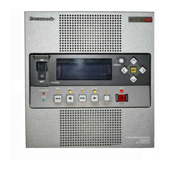
Page 5: Parts And Their Functions
Parts and their functions Front panel POWER CANCEL < > 4 5 6 7 8 STOP PLAY WARNING PREV NEXT SHIFT 1 POWER switch 8 SHIFT key After the unit’s operation has been shut down properly, Press this to search for recorded data. To search for a set this switch to the OFF position. -
Page 6: Rear Panel
Parts and their functions Rear panel SD OUT VIDEO REMOTE IN ACTIVE THROUGH HD SDI 1 2 3 SIGNAL AC IN 1 HD SDI IN connector (BNC) The HD SDI signals are supplied to this connector. 2 HD SDI through connector (BNC) The HD SDI input signals are passed straight through the unit and output here. -
Page 7: Basic Operations
Basic operations Startup Recording There are two recording mode settings: AUTO REC ON Set the power switch to the ON position. where data is recorded automatically in accordance with the variable frame rate camera, and AUTO REC OFF where The following message appears on the display panel. data is recorded manually. - Page 8 Basic operations Recording (continued) $ When AUTO REC is set to OFF 1. Check that the HD SDI signals are being input from the variable frame rate camera. 2. To start recording data, press the REC and PLAY keys. (Both the REC and PLAY lamps light.) 3.
- Page 9 Basic operations Playback Setup $ To play back a clip immediately after startup Press the [1] (right) key in any mode except REC, and set the unit to the MENU mode. When the PLAY key is pressed, the selected clip is played back.
-
Page 10: Menu Selection
Menu selection Basic screen 1 Menu selection screen Basic screen 2 (An item can be selected using the [1 ] and [! ] keys.) CLIP SETUP MENU1 MENU2 Basic screens 1 and 2 Basic screens 1 and 2 show the information required for 3 Output format/remaining hard disk drive memory dis- normal operations. - Page 11 Menu selection CLIP screen SETUP screen Names of the recorded clips and their durations appear on The setup menu settings are performed on this screen. this screen. The clip deletion method is selected on the screen. [ U S E R - S E T U P ] H D P B F M T 1 0 8 0 / 2 4 P 1 2 3 4 5 6 7 8...
-
Page 12
Menu selection HDD screen On this screen, some data is saved into a part of the hard disk drive’s memory that is free and then loaded to check that the drive is working properly. H D D V e r i f y S TA R T O K ? Y E S
... -
Page 13: Setup Menu
Setup menu Menu item Parameter Description HD PB FMT 1080/23psf For selecting the output format. 1080/24psf (Default)1080/25psf O23psf = 23.98psf, 59i = 59.94i 1080/50i OBear in mind that if the systems for the reference frequency at the 1080/59i camera side and for the unit’s output frequency are at variance 1080/60i when LOCK has been selected as the INCOME LOCK setting, the... - Page 14 Setup menu Menu item Parameter Description TC REGEN CONV (Default) For selecting the time code which is to be output from the display panel or RS-422 connector. CONV: Time code resulting from the conversion of the head or syn- chronization point as 00:00:00:00. ORG: Time code during recording.
-
Page 15: Time Code (Tc) And User's Bit (Ub)
Time code (TC) and user’s bit (UB) 24P synchronized playback TC/UB display at the SD OUT connector O Recorded clips shot at the 24P frame rate setting must be used. If any other clips are used, the value of the time code which is output will be adversely affected. - Page 16 Time code (TC) and user’s bit (UB) When CONV is selected as the TC REGEN setting, the values of the time code which are output to the display panel, remote controller, SD OUT connector and HD SDI OUT connector may not be the same values in all locations. (See table below) Time code values which are output for 1 second for each output format Output format Display panel...
-
Page 17: Input/Output Formats
Input/output formats E-E mode (when the same signals as the input signals are output) O Only format conversion is possible with E-E mode outputs. O The output in the E-E mode is synchronized with the input. This means that, when the input is 60p, the output will always be set to the output format with a frequency whose decimal places have been rounded up. -
Page 18: Troubleshooting
Troubleshooting Indication Action to be taken Unit fails to start up normally. Check that the AC power cable is connected to the AC input socket and that AC power is supplied. No operating displays appear even after 5 If there are no problems in this respect, contact your dealer. minutes. -
Page 19: Error Displays
Error displays ALARM screen When ALARM MSG on the setup menu is set to ON, the ALARM screen is displayed when an error has occurred. This screen displays the errors and warnings. The same error details appear on both the alarm screen and log screen. 1 1 : 1 1 : 1 1 T E M P E R R 1 S I L N T B A C K... -
Page 20: Specifications
Specifications Power Source: 220T230 Vw10%, 50/60 Hz w10% Power consumption: 98 W indicates safety information. Operating temperature: 5 to 35 ˚C Storage temperature: j10 to 50 ˚C Operating humidity: 10% to 80% Storage humidity: 5% to 90% Weight: 15 kg Dimensions:(WkHkD) 210k222k492 mm Recording time:... - Page 21 21 (E)
- Page 22 Panasonic Broadcast Europe Panasonic Broadcast Europe Ltd West Forest Gate, Wellington Road, Wokingham, Berkshire RG40 2AQ U.K. Tel: 0118 902 9200 Panasonic Broadcast Europe GmbH Hagenauer Str. 43, 65203 Wiesbaden-Biebrich Deutschland Tel: 49-611-1816-0 F0702Y1072 @ Printed in Japan...