Table of Contents
Quick Links
1
SERVICE MANUAL
Level 1&2
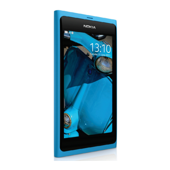
Nokia N9
RM-696
Transceiver characteristics
Band
EGSM 850/900/1800/1900 MHz
WCDMA HSPA 850/900/1700/1900/2100 MHz
Display
3.9" OLED display, 16:9 widescreen aspect ratio,
854 x 480 resolution
Camera
8 Mpx Carl Zeiss autofocus camera with CMOS
sensor, Dual LED flash, 1280x720 30fps HD video
recording
Operating System
Meego
Connections:
WLAN 802.11 a/b/g/n
NFC (Near Field Communication)
Micro USB 2.0
Bluetooth 2.1
Stereo audio out via 3.5mm AV connector
Transceiver with BV-5JW battery pack
Talk time
GSM: Up to 11 hours
WCDMA: Up to 7 hours
Note:
Talk times are dependent on network parameters
and phone settings
Confidential | Copyright © 2011 Nokia | All rights reserved
Nokia N9 (RM-696)
L1L2 Service Manual
Standby
GSM: Up to 380 hours
WCDMA: Up to 450 hours
Version 1.0
Table of Contents

Related Manuals for Nokia RM-696


Summary of Contents for Nokia RM-696
- Page 1 GSM: Up to 11 hours GSM: Up to 380 hours WCDMA: Up to 7 hours WCDMA: Up to 450 hours Note: Talk times are dependent on network parameters and phone settings Confidential | Copyright © 2011 Nokia | All rights reserved Version 1.0...
-
Page 2: Table Of Contents
BATTERY INFORMATION ..............................8 EXPLODED VIEW ................................. 9 SERVICE DEVICES ................................10 SOFTWARE UPDATE ................................11 DISASSEMBLY INSTRUCTIONS ............................12 10. ASSEMBLY HINTS ................................21 11. SOLDER COMPONENTS ..............................23 Confidential | Copyright © 2011 Nokia | All rights reserved Version 1.0... - Page 3 1.7.2011 First approved version The purpose of this document is to help NOKIA service levels 1 and 2 workshop technicians to carry out service to NOKIA products. This Service Manual is to be used only by authorized NOKIA service suppliers, and the content of it is confidential. Please note that NOKIA provides also other guidance documents (e.g.
-
Page 4: Copyright
Nokia operates a policy of continuous development. Nokia reserves the right to make changes and improvements to any of the products described in this document without prior notice. Under no circumstances shall Nokia be responsible for any loss of data or income or any special, incidental, consequential or indirect damages howsoever caused. -
Page 5: Warnings And Cautions
3. Use only approved components as specified in the parts list. 4. Ensure all components, modules screws and insulators are correctly re–fitted after servicing and alignment. 5. Ensure all cables and wires are repositioned correctly Confidential | Copyright © 2011 Nokia | All rights reserved Version 1.0... -
Page 6: Esd Protection
Nokia N9 (RM-696) L1L2 Service Manual 3. ESD PROTECTION Nokia requires that service points have sufficient ESD protection (against static electricity) when servicing the phone. Any product of which the covers are removed must be handled with ESD protection. The SIM card can be replaced without ESD protection if the product is otherwise ready for use. -
Page 7: Care And Maintenance
All of the above suggestions apply equally to the product, battery, charger or any accessory. Confidential | Copyright © 2011 Nokia | All rights reserved Version 1.0... -
Page 8: Battery Information
Batteries’ performance is particularly limited in temperatures well below freezing. Do not dispose batteries in a fire! Dispose of batteries according to local regulations (e.g. recycling). Do not dispose as household waste. Confidential | Copyright © 2011 Nokia | All rights reserved Version 1.0... -
Page 9: Exploded View
AV FLEX I0022 I0021 MAIN FLEX USB DOOR NFC ANTENNA I0023 I0001 I0024 Only available Not reuseable Repair/swap Ver. 1.0 as assembly after removal only in level 3 Confidential | Copyright © 2011 Nokia | All rights reserved Version 1.0... -
Page 10: Service Devices
For more information, refer to the Service Bulletin (SB-011) on Nokia Online. Supplier or manufacturer contacts for tool re-order can be found in “Recommended service equipment” document on Nokia Online. Confidential | Copyright © 2011 Nokia | All rights reserved Version 1.0... -
Page 11: Software Update
To use the FLS-5 Flash Dongle, follow the user guide inside the sales package. Please check always for the latest version of flash software, which is available on Nokia Online. Confidential | Copyright © 2011 Nokia | All rights reserved... -
Page 12: Disassembly Instructions
5) Remove the USB DOOR by pulling it to direction 6) Open the SIM DOOR by pulling the release notch to shown. direction shown. Pull out and remove the SIM DOOR. Confidential | Copyright © 2011 Nokia | All rights reserved Version 1.0... - Page 13 12) Use the SRT-6 to open the left side of the DISPLAY between the DISPLAY ASSEMBLY and the PLASTIC ASSEMBLY. BODY. Be careful not to damage the shown flex located halfway the top side. Confidential | Copyright © 2011 Nokia | All rights reserved Version 1.0...
- Page 14 ASSEMBLY. 17) Use the SS-93 to disconnect the two DISPLAY 18) Remove the DISPLAY ASSEMBLY. ASSEMBLY connectors. Be careful not to damage the connectors or any nearby components. Confidential | Copyright © 2011 Nokia | All rights reserved Version 1.0...
- Page 15 22) Unscrew the six Torx+ size 4 screws of the tweezers. CHASSIS. Do not use them again. Discard them. 23) Remove the CHASSIS with the tweezers. 24) Remove the CHASSIS SIDE HOOK with the tweezers. Confidential | Copyright © 2011 Nokia | All rights reserved Version 1.0...
- Page 16 30) Disconnect the FRONT CAMERA FLEX connector careful not to damage the connector or any nearby with the SS-93. Be careful not to damage the components. connector or any nearby components. Confidential | Copyright © 2011 Nokia | All rights reserved Version 1.0...
- Page 17 35) Unscrew the two screws of the IHF SPEAKER FLEX 36) Pull out and flip open the IHF SPEAKER FLEX with with a Phillips size 00 screwdriver. the tweezers. Confidential | Copyright © 2011 Nokia | All rights reserved Version 1.0...
- Page 18 Do not use it again. Discard it. as shown. 41) Remove the EARPIECE HOUSING LID. Do not use it 42) Lever out the EARPIECE with the dental tool. again. Discard it. Confidential | Copyright © 2011 Nokia | All rights reserved Version 1.0...
- Page 19 47) Lever out the RAPU SHIELDING LID with the SS-93. 48) Remove the RAPU SHIELDING LID with the Be careful not to damage any nearby components. tweezers. Do not use it again. Discard it. Confidential | Copyright © 2011 Nokia | All rights reserved Version 1.0...
- Page 20 52) Remove the NFC SHIELDING LID with the Be careful not to damage any nearby components. tweezers. Do not use it again. Discard it. 53) The Nokia N9 disassembly is now complete. -END OF DISASSEMBLY- Confidential | Copyright © 2011 Nokia | All rights reserved Version 1.0...
-
Page 21: Assembly Hints
5) Tighten the six TORX+ size 4 screws to the torque 6) Tighten the three TORX+ size 4 screws to the of 15 Ncm. torque of 15 Ncm. Confidential | Copyright © 2011 Nokia | All rights reserved Version 1.0... - Page 22 Nokia N9 (RM-696) L1L2 Service Manual 7) Tighten the two TORX+ size 4 screws to the torque of 8 Ncm. Confidential | Copyright © 2011 Nokia | All rights reserved Version 1.0...
-
Page 23: Solder Components
Nokia N9 (RM-696) L1L2 Service Manual 11. SOLDER COMPONENTS Solder component information not available currently. This will be updated later. Confidential | Copyright © 2011 Nokia | All rights reserved Version 1.0...