Bosch Conettix D6600 Installation And Operation Manual
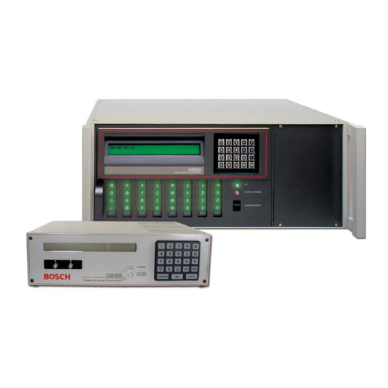
Communications receiver/gateway
Hide thumbs
Also See for Conettix D6600:
- Manual (185 pages) ,
- Installation and operation manual (88 pages) ,
- Operation and installation manual (36 pages)

Related Manuals for Bosch Conettix D6600


Summary of Contents for Bosch Conettix D6600
- Page 1 Conettix D6600/D6100i Installation and Operation Guide Communications Receiver/Gateway...
- Page 2 Conettix D6600/D6100i | Installation and Operation Guide | Trademarks Trademarks ® ® ® Microsoft , Windows , Windows NT are either registered trademarks or trademarks of Microsoft Corporation in the United States and/or other countries. ® Ademco is a registered trademark of Alarm Device Manufacturing Corporation.
-
Page 3: Table Of Contents
Conettix D6600/D6100i | Installation and Operation Guide | Contents Contents Introduction ..........5 10.0 D6600/D6100i Operation........17 10.1 Process Flow ............. 17 Emergency Procedures ........6 10.1.1 Receiver Handshake and Kiss-Off ....17 Card Functions and Locations ......6 D6600 ..............6 10.1.2 Message Verification ........17 3.1.1... - Page 4 Conettix D6600/D6100i | Installation and Operation Guide | Contents 17.0 Service Information ........35 Tables Table 1: D6600/D6100i Supported Communication Formats ......5 Figures Table 2: Power LED Indications......6 Figure 1: D6600 Communications Table 3: System Trouble LED........7 Receiver/Gateway (Front View)....6 Table 4: D6600 Line Cards and Modules ....
-
Page 5: Introduction
Conettix D6600/D6100i | Installation and Operation Guide | 1.0 Introduction 1.0 Introduction Table 1: D6600/D6100i Supported Communication Formats The Conettix D6600/D6100i Communications Receiver/Gateway offers several unique features: • Modular construction with plug-in circuit boards Acron Super Fast ROBOFON* for quick, easy service ®... -
Page 6: Emergency Procedures
Conettix D6600/D6100i | Installation and Operation Guide | 2.0 Emergency Procedures 2.0 Emergency Procedures 3.0 Card Functions and Locations Section 17.0 Service Information on page 35 of this guide contains a Service Information form. Keep this form D6600 current and accessible to central station personnel at all times in case of emergency. -
Page 7: Line Cards And Modules
Conettix D6600/D6100i | Installation and Operation Guide | 3.0 Card Functions and Locations Table 3: System Trouble LED System Trouble LED Status Solid Red Clear No System Trouble Any System Trouble* Refer to Appendix B: D6600/D6100i Internal Messages in the D6600/D6100i Computer Interface Manual (P/N: 4998122703). -
Page 8: Rear View
Conettix D6600/D6100i | Installation and Operation Guide | 3.0 Card Functions and Locations 3.1.3 Rear View The D6600 has input and output pin connector sockets for up to eight line cards, network option (if installed), and one CPU card. It also has slots for connecting these cards to their corresponding terminator cards. -
Page 9: Front Panel
Conettix D6600/D6100i | Installation and Operation Guide | 4.0 D6600 Specific Cards 4.0 D6600 Specific Cards D6100i The difference between the D6100 and D6640/D6641 Line Cards and D6645 the D6100i is the D6100i has a built in Line Terminator Card Ethernet connection. -
Page 10: D6640/D6641 Led Descriptions
Conettix D6600/D6100i | Installation and Operation Guide | 4.0 D6600 Specific Cards 4.1.1 D6640/D6641 LED Descriptions 4.1.2 Card Installation The LED is active until the system acknowledges the Discharge static electricity from your body entire transmission and the telephone line is ready to by touching the receiver’s internal frame... -
Page 11: D6640/D6641Telephone Line Monitoring Voltage
Conettix D6600/D6100i | Installation and Operation Guide | 4.0 D6600 Specific Cards 4.1.3 D6640/D6641Telephone Line Monitoring Figure 9: Removing and Installing Terminator Voltage Card The line card continuously monitors the telephone line voltage. Normal operating voltage ranges from 1.8 VDC to 2.5 VDC. Any voltage above 2.5 VDC causes the line to appear good (restoral) and an indication appears if any voltage is below 1.8 VDC. -
Page 12: D6610 Cpu Card And D6615 Cpu Terminator Card
Conettix D6600/D6100i | Installation and Operation Guide | 5.0 Power Supply Modules (D6600 Only) 4.2.3 Card Removal and Replacement D6610 CPU Card and D6615 CPU Terminator Card Remove power to the D6600 before 4.2.1 D6610 CPU Card Connection removing, replacing, or installing the CPU... -
Page 13: Installation
Conettix D6600/D6100i | Installation and Operation Guide | 7.0 Installation 7.0 Installation Install the D6600/D6100i according to UL Standard 827 for Central Station Burglar Alarm Systems. Use in All Installations a central station that has backup AC power (per UL Install the D6600/D6100i Communications 827) to supervise certificated accounts. -
Page 14: Rack Mount Instructions
Conettix D6600/D6100i | Installation and Operation Guide | 8.0 Standby Power 10. Turn the D6600 power switch on. The D6100i 8.0 Standby Power starts as soon as you plug in the AC Transformer. During a loss of AC power, the receiver automatically 11. -
Page 15: Minimum Standby Battery
Conettix D6600/D6100i | Installation and Operation Guide | 9.0 Input and Output Ports Table 6: Calculating Standby Current for the D6600 Device 12 V Battery Standby Current UPS AC Standby Current D6600 (one D6640/ D6641/D6645 800 mA 800 mA 350 mA... -
Page 16: Ups Monitoring Through Cpu Programmable Input Ports
Conettix D6600/D6100i | Installation and Operation Guide | 9.0 Input and Output Ports UPS Monitoring through CPU Figure 14: Input Wiring for Reverse Configuration Programmable Input Ports Use the CPU programmable input port to connect the external UPS to the D6600/D6100i for power monitoring. -
Page 17: D6600/D6100I Operation
Conettix D6600/D6100i | Installation and Operation Guide | 10.0 D6600/D6100i Operation 10.0 D6600/D6100i Operation Some communicators wait approximately 30 sec for the proper handshake tone. 10.1 Process Flow Others hang up immediately if they hear an improper handshake tone. Others have a 10.1.1 Receiver Handshake and Kiss-Off... -
Page 18: Buzzer Operation
Conettix D6600/D6100i | Installation and Operation Guide | 10.0 D6600/D6100i Operation 10.1.6 Buzzer Operation 10.2 Normal Operation Mode In the Manual Mode, an Operator Alert Buzzer sounds In Normal Operation Mode, the D6600/D6100i sends when a message is received until you press the messages immediately or in blocks to reporting devices [ACKNOWLEDGE] key. -
Page 19: Operating In Manual Mode
Conettix D6600/D6100i | Installation and Operation Guide | 10.0 D6600/D6100i Operation 10.3 Operating in Manual Mode 10.4 Keypad Menu Operation If all reporting devices (such as printers and computers) 10.4.1 Log In fail, the D6600/D6100i reverts to Manual Mode until a device returns to service. -
Page 20: Event Buffer Display
Conettix D6600/D6100i | Installation and Operation Guide | 10.0 D6600/D6100i Operation 10.4.3 Event Buffer Display D6600 D6600 D6100 No more system Shows event buffer contents in D6100 troubles remain the order the events are D6600 D6100 SYSTEM received. TROUBLE Refer to Section 15.0 Troubleshooting Guide on If multiple lines of text are received, page 30 for more information. -
Page 21: Skip Current Automation Event
Conettix D6600/D6100i | Installation and Operation Guide | 10.0 D6600/D6100i Operation D6600 D6100 10.4.7 Skip Current Automation Event ENTER Use this option to skip the current Automation event. D6100 D6600 D6600: FUNCTION D6100: Enter password. D6600 D6600 default password: 6600... -
Page 22: Clear Pending Events
Conettix D6600/D6100i | Installation and Operation Guide | 10.0 D6600/D6100i Operation 10.4.9 Clear Pending Events 10.5 Busy Seconds (Line Busy) Reports Use this option to clear all pending events. The D6600 software monitors and reports when a call group of receiver lines cannot receive signals. The... -
Page 23: Two-Way Audio
Conettix D6600/D6100i | Installation and Operation Guide | 10.0 D6600/D6100i Operation 10.6.1 Enhancements and Changes 10.6 Two-Way Audio • Setting TWA by the selected Alarm Code allows When using the D6600/D6100i for Two-Way Audio one or multiple Alarm Codes to be selected. TWA... -
Page 24: Two-Way Audio Modes Of Operation
Conettix D6600/D6100i | Installation and Operation Guide | 10.0 D6600/D6100i Operation 10.6.2 Two-Way Audio Modes of Operation • Transfer: D6600/D6100i transfers the incoming line to another line; a flash operation occurs at the end of the alarm signal. The receiver dials the line programmed at Transfer Phone Number (refer to Menu Items 3.1.4.18 Flash [x 100ms] and 3.1.4.19... -
Page 25: Network Communications
Conettix D6600/D6100i | Installation and Operation Guide | 11.0 Network Communications 11.0 Network Communications Figure 15: Conettix Network System Connection Diagram - C900TTL-E/C900V2 and The Conettix D6600 and D6100i Communications Any Control Panel Receiver/Gateway systems support data network communications. This allows the receiver to connect to... -
Page 26: No Data Received Reports
Conettix D6600/D6100i | Installation and Operation Guide | 12.0 No Data Received Reports 12.0 No Data Received Reports Figure 16: Conettix Network System Connection Diagram - D9133TTL-E/DX4020 and 12.1 Description Bosch Control Panels If a message is garbled (incorrect checksum or... -
Page 27: Using The Central Station Automation System With The Receiver
Conettix D6600/D6100i | Installation and Operation Guide | 13.0 Using the Central Station Automation System with the Receiver 13.0 Using the Central Station Figure 18: Receiver System – Direct Connect Automation System with the Receiver If using a Bosch Security Systems, Inc. receiver,... -
Page 28: Central Station Tips
Conettix D6600/D6100i | Installation and Operation Guide | 14.0 Central Station Tips 14.0 Central Station Tips Figure 19: Receiver System – Standard/Network Automation 14.1 Back-up Receiver Spare circuit boards and receivers should be available at the central station. Keep a spare kit on hand. UL... -
Page 29: Proper Ground
Conettix D6600/D6100i | Installation and Operation Guide | 14.0 Central Station Tips 14.5 Proper Ground Connect the receivers to an earth ground, not a chassis or electrical ground. Measure the resistance of the receiver ground to another ground. If the meter reads above 2 Ω, check your receiver ground against a... -
Page 30: Troubleshooting Guide
Section 3.0 Card Functions and Locations on page 6). Do not attempt to repair individual assemblies. Return any failed assemblies to Bosch Security Systems, Inc. for testing and repair. Use this Troubleshooting Guide to identify failed modular components. - Page 31 Conettix D6600/D6100i | Installation and Operation Guide | 15.0 Troubleshooting Guide Table 11: Hardware Troubleshooting Guide (continued) Problem Symptom Solution • • Operator alert System stalled Check watchdog LED on the inside of the door behind the buzzer cannot be keypad.
- Page 32 Conettix D6600/D6100i | Installation and Operation Guide | 15.0 Troubleshooting Guide Table 11: Hardware Troubleshooting Guide (continued) Problem Symptom Solution • D6200 cannot D6200 network connection is Ensure that the Ethernet connection light on the network connect to the defective, missing, or has interface module for the PC running D6200 Software is on.
-
Page 33: Specifications
Consult the dealer or an experienced radio/TV technician for help. Any modifications made to this device that are not approved by Bosch Security Systems, Inc. may void the authority granted to the user by the FCC to operate this equipment. - Page 34 Conettix D6600/D6100i | Installation and Operation Guide | 16.0 Specifications Industry Canada D6600 1249A-8925A D6100i 1249A-6100 This product meets the applicable Industry Canada technical specifications. The Ringer Equivalence Number is an indication of the maximum number of devices allowed to be connected to a telephone interface.
-
Page 35: Service Information
17.0 Service Information (EMERGENCY DATA SHEET) In a central station emergency, use this information to contact the necessary people and enable Bosch Security Systems, Inc. Customer Service Personnel to help you with your emergency. Ask your supervisor to provide the following information: Supervisor’s Name:... - Page 36 Bosch Security Systems, Inc. 130 Perinton Parkway Fairport, NY 14450-9199 (800) 289-0096 © 2007 Bosch Security Systems, Inc. 4998122704-02...