Table of Contents
Quick Links
Table of Contents

Related Manuals for GE DEH-40417


Summary of Contents for GE DEH-40417
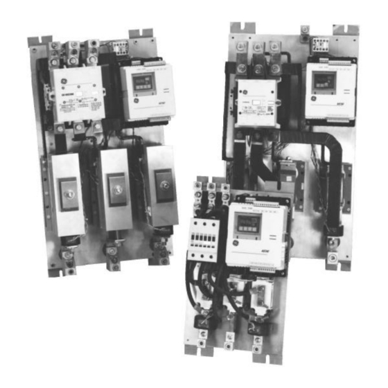
- Page 1 DEH-40417 ® ASTAT -IBP Plus Solid State Starters Service Instructions...
- Page 3 Features may be described herein that are not present in all hardware and software systems. GE Electrical Distribution & Control assumes no obligation of notice to holders of this document with respect to changes subsequently made.
-
Page 4: Table Of Contents
-IBP Plus Service Instructions Table of Contents Cover Removal and Replacement ...1 Logic Board Replacement ...2 Power Supply Board Replacement ...3 Protection Board Replacement ...5 SCR Module Replacement (Sizes K, L, and Y) ...6 SCR Module Replacement (Sizes M, Z, and N)...7 SCR Module Replacement (Sizes P, Q, and R) ...8... -
Page 5: Cover Removal And Replacement
WARNING: Power must be removed from the ASTAT- IBP before any servicing operation. AVERTISSEMENT: Le courant doit être enlevé du ASTAT-IBP avant de procéder à toute opération de service. Cover Removal and Replacement 1. Remove the two 12-point terminal connectors by inserting a flat-head screwdriver between the terminal connector and the ASTAT-IBP cover, as illustrated in Figure 1. -
Page 6: Logic Board Replacement
6. Reinstall the plastic cover and the terminal connectors as described in steps 3–4 of Cover Removal and Replacement. Logic Board Screws Unplug Cable Power Supply Ribbon Board Figure 3. Logic board and part locations. Logic Board Cable Ribbon Figure 4. Removing the Logic Board. -
Page 7: Power Supply Board Replacement
Power Supply Board Replacement The Power Supply Board is located as shown in Figure 5. It contains gray and orange transformers visible from the sides. 1. Remove the following components: a. The cover, as described in steps 1–2 of Cover Removal and Replacement. - Page 8 7. Reconnect the red and white gate wires to the four- point Terminal Boards, one on the component side and two on the solder side of the Power Supply Board, as illustrated in Figures 8, 9, and 10. 8. Secure the Power Supply Board with the four screws removed earlier.
-
Page 9: Protection Board Replacement
Removal and Replacement. b. The Logic Board, as described in steps 2–3 of Logic Board Replacement. c. The Power Supply Board, as described in steps 2– 5 of Power Supply Board Replacement. 2. Remove the six wire connectors from the Protection Board, as shown in Figure 11. -
Page 10: Scr Module Replacement (Sizes K, L, And Y)
® ASTAT -IBP Plus Service Instructions SCR Module Replacement (Sizes K, L, and Y) This procedure requires the following tools and materials: • #2 Philips-head screwdriver, torque wrench • Scotchbrite or equivalent abrasive • Mild solvent to clean mounting surfaces •... -
Page 11: Scr Module Replacement (Sizes M, Z, And N)
SCR Module Replacement (Sizes M, Z, and N) This procedure requires the following tools and materials: • #2 Philips-head screwdriver, torque wrench • Scotchbrite or equivalent abrasive • Mild solvent to clean mounting surfaces • Electrolube 2GX or equivalent thermal grease 1. -
Page 12: Scr Module Replacement (Sizes P, Q, And R)
® ASTAT -IBP Plus Service Instructions SCR Module Replacement (Sizes P, Q, and R) This procedure requires the following tools and materials: • " wrench, " Allen wrench, torque wrench • Scotchbrite or equivalent abrasive • Mild solvent to clean mounting surfaces •... -
Page 13: Scr Module Replacement (Size S)
SCR Module Replacement (Size S) This procedure requires the following tools and materials: • " wrench, " wrench, torque wrench • Scotchbrite or equivalent abrasive • Mild solvent to clean mounting surfaces • Electrolube 2GX or equivalent thermal grease 1. Disconnect the control wiring harness for the SCRs to be replaced. - Page 14 ® ASTAT -IBP Plus Service Instructions 7. Lift out the SCR Module, as shown in Figure 21. Retain all parts and hardware for reassembly with the replacement Module. 8. Remove the threaded stud from the SCR Module and attach it to the new Module. Tighten to 200 in- lb torque.
-
Page 15: Troubleshooting Guide
C6 (located next to the black heatsink on the right edge of the power supply board) and the (+) lead of voltmeter on top lead of Diode AD21 or R25 (located on the upper right corner of the power supply board.) -
Page 16: Renewal Parts List
Current Transformer MOV (with terminals and insulators) Terminal Strip (Logic P.C.B.) Terminal Strip (Control Power Input to ASTAT) Fuses on Power Supply Board (Bussman Type GMC, 250 Vac) Ribbon Cable, Top-Logic Board to Power Supply Board Ribbon Cable, Bottom-Logic Board to... - Page 18 Should further information be desired or should particular problems arise that are not covered sufficiently for the purchaser’s purposes, the matter should be referred to the GE Company. General Electric Company 41 Woodford Ave., Plainville, CT 06062...