Kenwood AT-130 Instruction Manual
Antenna tuner
Hide thumbs
Also See for AT-130:
- Service manual (54 pages) ,
- Service manual (53 pages) ,
- Service manual (46 pages)

Related Manuals for Kenwood AT-130


Summary of Contents for Kenwood AT-130
- Page 2 FEATURES The Model AT-130 is designed to satisfy your 1. The AT-130 is a high performance H F antenna antenna-tuning requirements. It has been manu- tuner and is a modification of the popular factured with the quality and performance that AT-200 antenna tuner.
- Page 3 ~ spueq L'6Z uoo& 'pa3uelequn 'Xew 4'&) 'Pueq ssa1 ueyl wnw!ldo .y3$ew dHfl )adAl pnls ww09 (,,8/&-Z) wwz91 (1,9) (,,PIL-~)
- Page 4 Accessories: Interconnection Cable Carefully unpack your AT-1 30 Antenna Tuner To connect your AT-130 with the TS-130S(V). and verify the following accessories are included. or other transceiver, an interconnection cable is . . . 1 copy Operating manual required. 1 piece Mounting bracket Refer to Figure1 -1 for details.
-
Page 5: Section 2. Controls And Their Functions
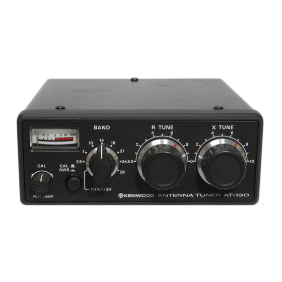
- - - JIIIII~~IIIII~~~~~~I~~IIIII~~IIIII~~IIII~~~IIIII~~IIIII~~IIIII~~IIIII~~IIIII~~IIIII~~IIII~~~IIIII*~IIIII~IIIIII~~IIIII-~ SECTION 2. CONTROLS AND THEIR FUNCTIONS ~~~~~~~~~~~~~~~~~~~I~-~IIII~.~IIII~~~IIII~.~~III~.~IIII~~~IIII~.~IIII~.~IIII~.~IIII~.~II~I~.~IIII~. ANTENNA TUNER AT- PULL LAMP Figure 2-1 Front view 1. Meter 4. BAND Switch The meter reads SWR (standing-wave ratio) and Set this switch to the band in which you are may be illuminated by an external power source. - Page 6 Measuring antenna system SWR (ii)Using a tube power amplifier transceiver (such as a TS-820) (i) Using an all solid-state transceiver (such a s a Connect the transceiver (or transmitter) and TS-130s or TS-130V) dummy load (or antenna) through the AT-1 Before setting up the antenna coupler, first shown in Figure 3-3.
- Page 7 Table 3-1 shows approximate control positions Adjusting the Antenna Coupler The antenna coupler is used to match a trans- for coupler adjustment. mitter to an antenna system when i t s SWR is too high (i.e., greater than 1.5:1 SWR). Place the BAND switch to the same band Table 3-1 setting as your transceiver (as shown in Figure...
- Page 8 Mobile Installation Securely install the Mobile Mount using four lock washers, four flat washers, and four screws and nuts. Install the AT-130 in the Mobile Mount by four wing bolts and polyethylene washers. Adjust the tilt before tightening the bolts.
- Page 9 SWR measurement. Antenna Coupler The universal matching circuit is capable of matching 20 t o 300n loads to the input Figure 4-1. AT-130 Block Diagram impedance.
- Page 10 1. General lnformation include a photocopy of the bill of sale, Your AT-130 has been factory aligned and tested or other proof of purchase showing the to specification before shipment. Under normal date of sale. circumstances, it wili operate in accordance with these operating instructions.
- Page 11 Circuits and specifications are subject to change for improvement. LAMP 12V...
- Page 12 6 3 7 4 Stelnbach TS lndustr~estrasse 8 A West Germany TRIO-KENWOOD ELECTRONICS, N.V. Leuvensesteenweg 5 0 4 8 1 9 3 0 Zaventem B e l g ~ u m TRIO-KENWOOD [AUSTRALIA) PTY. LTD. 4 E Woodcock Place Lane Cove N S W 2066...