Table of Contents
Table of Contents

Related Manuals for Honeywell Primus 880


Summary of Contents for Honeywell Primus 880
- Page 2 Honeywell International Inc. Commercial Electronic Systems 5353 W. Bell Rd. Glendale, Arizona 85308- - 3912 U.S.A. (CAGE 55939) PRIMUSr 880 Digital Weather Radar System Pilot’s Guide Revised January 2006 Printed in U.S.A. Pub. No. A28--1146--102--03 September 1996...
-
Page 3: Table Of Contents
PRIMUSr 880 Digital Weather Radar System Table of Contents Section Page 1. INTRODUCTION ...... - Page 4 PRIMUS 880 Digital Weather Radar System Table of Contents (cont) Section Page 5. RADAR FACTS (cont) Rain Echo Attenuation Compensation Technique (REACT) ........
- Page 5 ........4--3 WI--880 Indicator Test Pattern With TEXT FAULT Enabled .
- Page 6 PRIMUS 880 Digital Weather Radar System Table of Contents (cont) List of Illustrations (cont) Figure Page 5--1 Positional Relationship of an Airplane and Storm Cells Ahead as Displayed on Indicator ..5--2 Antenna Beam Slicing Out Cross Section of Storm During Horizontal Scan .
- Page 7 PRIMUS 880 Digital Weather Radar System Table of Contents (cont) List of Illustrations (cont) Figure Page 5--32 Turbulent ........
- Page 8 3--3 Rainfall Rate Color Coding ....3-13 3--4 WC--880 Controller Target Alert Characteristics . . . 3-17 3--5 WC--884 Controller Target Alert Characteristics .
-
Page 9: Introduction
PRIMUSr 880 Digital Weather Radar System Introduction The PRIMUS 880 Digital Weather Radar System is a lightweight, X- band digital radar with alphanumerics designed for weather detection (WX) and ground mapping (GMAP). The primary purpose of the system is to detect storms along the flightpath and give the pilot a visual indication in color of their rainfall intensity and turbulence content. - Page 10 This feature expands the use of the radar indicator to display information such as checklists, short and long range navigation displays (when used with a Honeywell DATA NAV system) and electrical discharge data from Honeywell’ s LSZ- 850 Lightning Sensor System (LSS).
-
Page 11: System Configurations
880 Digital Weather Radar System. A single or dual â Honeywell EFIS can be added to the stand- alone configuration. In such a case the electronic horizontal situation indicator (EHSI) repeats the data displayed on the radar indicator. System control remains with the radar indicator. - Page 12 PRIMUSr 880 Digital Weather Radar System STAND- ALONE CONFIGURATION INDICATOR WU- 880 WI- 880 SINGLE OR DUAL EFIS OPTION EFIS ONLY CONFIGURATION CONTROLLER WU- 880 WC- 880 STAB SECT PULL PULL GMAP GAIN RADAR TILT STAB SECT PULL PULL GMAP...
-
Page 13: Dual Control Mode Truth Table
PRIMUSr 880 Digital Weather Radar System The third system configuration is similar to the second except that a Honeywell multifunction display (MFD) system is added. As before, single or dual controllers can be used. When a single controller is used, all displays show the same radar data. - Page 14 PRIMUS 880 Digital Weather Radar System NOTES: 1. ON is used to indicate any selected radar mode. 2. “SLV” means that displayed data is controlled by opposite side controller. 3. XXX/2 means that display is controlled by appropriate on--side control for the antenna sweep direction associated with that control.
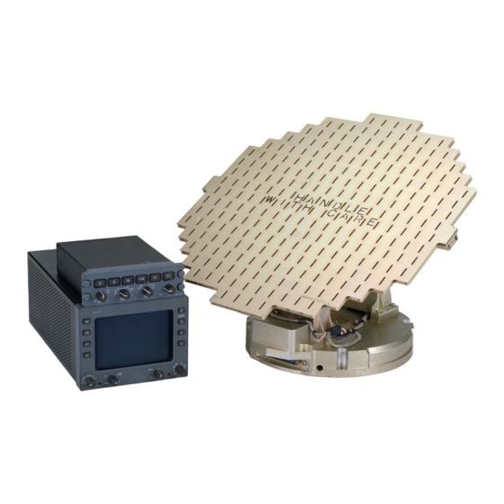
- Page 15 PRIMUSr 880 Digital Weather Radar System WU- 880 RTA WC- 884 CONTROLLER WI- 880 INDICATOR WC- 880 CONTROLLER AD- 46691@ Typical PRIMUS 880 Weather Radar Components â Figure 2- 2 A28- 1146- 102- 00 System Configurations 2-5/(2-6 blank)
-
Page 16: Operating Controls
WI- 880 WEATHER RADAR INDICATOR OPERATION All controls used to operate the system display shown in figure 3- 1, are located on the WI- 880 Weather Radar Indicator front panel. There are three basic controllers that are described in this section, they are (in... - Page 17 GAIN TILT PULL PULL SBY LX AD- 46693- R1@ WI- 880 Weather Radar Indicator Front Panel View Figure 3- 2 Display Area See figure 3- 3 and the associated text which explains the alphanumeric display. A28- 1146- 102- 00 Operating Controls...
- Page 18 WX/T VAR V A R ! IN PRIORITY ORDER. AD- 46694- R2@ WI- 880 Weather Radar Indicator Display Screen Features Figure 3- 3 Function Switch A rotary switch used to select the following functions: OFF- This position turns off the radar system.
-
Page 19: Rainfall Rate Color Coding
PRIMUSr 880 Digital Weather Radar System If WX is selected before the initial RTA warmup period is over (approximately 90 seconds), the white WAIT legend is displayed in the mode field. In wait mode, the transmitter and antenna scan are inhibited and the display memory is erased. When the warmup is complete, the system automatically switches to the WX mode. - Page 20 PRIMUS 880 Digital Weather Radar System FP (Flight Plan) -- The FP position puts the radar system in the flight plan mode, which clears the screen of radar data so ancillary data can be displayed. Examples of this data are: —...
- Page 21 PRIMUSr 880 Digital Weather Radar System WARNING FORCED STANDBY MODE MUST BE VERIFIED BY THE OPERATOR TO ENSURE SAFETY FOR GROUND PERSONNEL. TGT (Target) The TGT button is an alternate- action switch that enables and disables the radar target alert feature. Target alert is selectable in all but the 300- mile range.
-
Page 22: Target Alert Characteristics
PRIMUSr 880 Digital Weather Radar System Selected Range Minimum Target Target Range (NM) Depth (NM) (NM) 5- 55 10- 60 25- 75 50- 100 100- 150 200- 250 FP (Flight Plan) 5- 55 Target Alert Characteristics Table 3- 2 RCT (Rain Echo Attenuation Compensation Technique... - Page 23 PRIMUS 880 Digital Weather Radar System The radar antenna is normally attitude stabilized. It automatically compensates for roll and pitch maneuvers (refer to Section 5, Radar Facts, for a description of stabilization). The STB OFF annunciator is displayed on the screen.
- Page 24 PRIMUSr 880 Digital Weather Radar System BRT (Brightness) or BRT/LSS (Lightning Sensor System) The BRT knob is a single- turn control that adjusts the brightness of the display. Clockwise (cw) rotation increases display brightness and counterclockwise (ccw) rotation decreases brightness.
- Page 25 PRIMUSr 880 Digital Weather Radar System GAIN The GAIN knob is a single- turn rotary control and push/pull switch that is used to control the receiver gain. Push in on the GAIN switch to enter the system into the preset calibrated gain mode. Calibrated gain is the normal mode and is used for weather avoidance.
-
Page 26: Weather Radar Controller Operation
WC- 880 WEATHER RADAR CONTROLLER OPERATION The controls and display features of the WC- 880 Weather Radar Controller are indexed and identified in figure 3- 4. Brightness levels for all legend and controls on the indicator are controlled by the dimming bus for the aircraft panel. - Page 27 PRIMUSr 880 Digital Weather Radar System STAB SECT PULL PULL GMAP GAIN RADAR TILT AD- 46697- R1@ WC- 880 Weather Radar Controller Configurations Figure 3- 4 NOTES: 1. With a controller without built- in range control, range is controlled from the installed EFIS navigation display 2.
-
Page 28: Rainfall Rate Color Coding
PRIMUSr 880 Digital Weather Radar System RADAR This rotary switch is used to select one of the following functions. OFF - This position turns the radar system off. SBY (Standby) - This position places the radar system in standby; a ready state, with the antenna scan stopped, the transmitter inhibited, and the display memory erased. - Page 29 PRIMUSr 880 Digital Weather Radar System NOTES: 1. REACT’ s three functions (attenuation compensation, cyan field, forcing targets magenta) are switched on and off with the RCT switch. Refer to Section 5, Radar Facts, for a description of REACT. GMAP (Ground Mapping) - The GMAP position puts the radar system in the Ground Mapping mode.
- Page 30 PRIMUSr 880 Digital Weather Radar System The target alert mode can be used in the FP mode. With target alert on and the FP mode selected, the target alert armed annunciation (green TGT) is displayed. The RTA searches for a hazardous target from 5 to 55 miles and ±7.5 degrees of dead ahead.
- Page 31 PRIMUSr 880 Digital Weather Radar System TILT The TILT switch is a rotary control that is used to select the tilt angle of antenna beam with relation to the horizon. CW rotation tilts beam upward 0_ to 15_; ccw rotation tilts beam downward 0_ to - 15_. The range between +5_ and - 5_ is expanded for ease of setting.
-
Page 32: Wc--880 Controller Target Alert Characteristics
PRIMUSr 880 Digital Weather Radar System Selecting target alert forces the system to preset gain. Target alert can only be selected in the WX and FP modes. In order to activate target alert, the target must have the depth and... - Page 33 PRIMUS 880 Digital Weather Radar System WARNINGS 1. TURBULENCE CAN ONLY BE DETECTED WITHIN AREAS OF RAINFALL. THE PRIMUS 880 DIGITAL WEATHER RADAR SYSTEM CANNOT DETECT CLEAR AIR TURBULENCE. 2. UNDETECTED TURBULENCE CAN EXIST WITHIN ANY STORM CELL. REFER TO SECTION 5, RADAR FACTS, OF THIS GUIDE FOR ADDITIONAL INFORMATION.
- Page 34 PRIMUSr 880 Digital Weather Radar System WARNING LOW VARIABLE GAIN SETTINGS CAN ELIMINATE HAZARDOUS TARGETS FROM THE DISPLAY. In GMAP mode, variable gain is used to reduce the level of strong returns from ground targets. Minimum gain is attained with the control at its full ccw position. Gain increases as the control is rotated in a cw direction from full ccw at full cw position, the gain is at maximum.
-
Page 35: Weather Radar Controller Operation
PRIMUSr 880 Digital Weather Radar System WC- 884 WEATHER RADAR CONTROLLER OPERATION The controls and display features of the WC- 884 Weather Radar Controller are indexed and identified in figure 3- 5. Brightness levels for all legend and controls on the indicator are controlled by the dimming bus for the aircraft panel. -
Page 36: Wc--884 Controller Target Alert Characteristics
PRIMUSr 880 Digital Weather Radar System Selecting target alert forces the system into preset gain. Target alert can be selected in the WX and FP modes. To activate target alert, the target must have the depth and range characteristics described in table 3- 5:... - Page 37 PRIMUS 880 Digital Weather Radar System TRB (Turbulence Detection) TRB switch is used to select the turbulence detection mode of operation. The TRB mode can only be selected if the MODE switch is in the WX position and the selected range is 50 miles or less. The weather/turbulence mode is annunciated in the mode field with the green WX/T legend.
- Page 38 PRIMUSr 880 Digital Weather Radar System WARNINGS AVOID FLYING UNDER OVER STORMS, FREQUENTLY SELECT MANUAL TILT TO SCAN BOTH ABOVE AND BELOW YOUR FLIGHT LEVEL. ALWAYS USE MANUAL TILT FOR WEATHER ANALYSIS. RANGE RANGE is a rotary control used to select one of six ranges (10, 25, 50, 100, 200, and 300 NM).
-
Page 39: Rainfall Rate Color Coding
PRIMUSr 880 Digital Weather Radar System When the warmup is complete, the system changes the mode field from WAIT to STBY. TEST- This position selects the radar test mode. A test pattern is displayed to verify that system operates. The green TEST legend is displayed in the mode field. - Page 40 PRIMUSr 880 Digital Weather Radar System When GMAP is selected, a green GMAP legend is displayed and the color scheme is changed to cyan, yellow, magenta. Cyan represents the least reflective return, yellow is a moderate return, and magenta is a strong return.
-
Page 41: Hidden Modes
The VAR legend annunciates variable gain. Selecting RCT or TGT forces the system into preset gain. Preset gain is not annunciated. HIDDEN MODES The PRIMUS 880 has five hidden modes that are summarized as â follows: Forced Standby (FSBY) Override... -
Page 42: Roll Offset
PRIMUSr 880 Digital Weather Radar System Roll Offset Function - Roll offset permits exact compensation of the antenna roll to eliminate the effects of small errors in the aircraft radar installation. Constantly lopsided ground returns can be eliminated. (Refer to Section 5, Radar Facts, table 5- 5.) Entry Method - Using only one controller that is in the WX and variable gain modes, select RCT OFF. - Page 43 PRIMUSr 880 Digital Weather Radar System Entry Method - Selected by sequencing through the roll offset, pitch offset, and roll gain menus with the STAB button. (Refer to Section 5, Radar Facts, table 5- 10.) Control - Pull the GAIN knob out and use it.
-
Page 44: Normal Operation
PRIMUS 880 Digital Weather Radar System Normal Operation PRELIMINARY CONTROL SETTINGS Table 4--1 gives the proper power--up procedure for the PRIMUS Digital Weather Radar System. Step Procedure Verify that the system controls are in the positions described below before powering up the radar system:... - Page 45 PRIMUSr 880 Digital Weather Radar System Step Procedure When power is first applied the radar is in WAIT for approximately 90 seconds to allow the magnetron to warm up. Power sequences ON- OFF- ON lasting less than 3 seconds result in a 6- second wait period.
- Page 46 PRIMUS 880 Digital Weather Radar System TGT OR VAR ANNUNCIATOR TGT: TARGET ALERT P880 WX -- GREEN--SELECTED WX RANGE MODE -- AMBER TGT DETECTED ANNUNCIATIONS RINGS VAR: VARIABLE GAIN (AMBER) (WHITE) DTRK MAG1 FMS1 130 NM TEST TEXT AREA ANTENNA...
-
Page 47: Standby
PRIMUS 880 Digital Weather Radar System WI- -880 Indicator Test Pattern With TEXT FAULT Enabled Figure 4- -3 Standby When Standby is selected, and the radar is not in dual control mode (refer to table 2--1, dual control mode truth table, for dual control operation), the antenna is stowed in a tilt--up position and is neither scanning nor transmitting. - Page 48 Excessive losses in the radome seriously affect radar calibration. One possible means of verification are signal returns from known targets. Honeywell recommends that the pilot report evidence of weak returns to ensure that radome performance is maintained at a level that does not affect radar calibration.
-
Page 49: Radar Mode - Ground Mapping
TEST MODE The PRIMUS 880 Digital Weather Radar System has a self- test mode â and a maintenance function. In the self- test (TST) mode a special test pattern is displayed as illustrated earlier in this section. - Page 50 PRIMUSr 880 Digital Weather Radar System EFIS/MFD/ND - Faults are normally shown when test is selected. NOTES: 1. Some weather failures on EFIS are annunciated with an amber WX. 2. Some EFIS installations can power up with an amber WX if weather radar is turned off.
-
Page 51: Radar Facts
PRIMUSr 880 Digital Weather Radar System Radar Facts RADAR OPERATION The PRIMUS 880 Digital Weather Radar works on an echo principle. â The radar sends out short bursts of electromagnetic energy that travel through space as a radio wave. When the traveling wave of energy strikes a target, some of the energy reflects back to the radar receiver. -
Page 52: Cells Ahead As Displayed On Indicator
PRIMUSr 880 Digital Weather Radar System AIRCRAFT HEADING +0.6 AD- 12055- R2@ Positional Relationship of an Airplane and Storm Cells Ahead as Displayed on Indicator Figure 5- 1 The drawing is laid out to simulate the face of the indicator with the semicircular range marks. -
Page 53: Antenna Beam Slicing Out Cross Section Of Storm During Horizontal Scan
PRIMUSr 880 Digital Weather Radar System at it from above, as shown in figure 5- 2. The height of the slice selected for display depends upon the altitude and also upon the upward or downward TILT adjustment made to the antenna. -
Page 54: Sea Returns
PRIMUSr 880 Digital Weather Radar System When the antenna is tilted downward for ground mapping, two phenomena may occur that can confuse the pilot. The first is called ” The Great Plains Quadrant Effect”that is seen most often when flying over the great plains of central United States. -
Page 55: Tilt Management
PRIMUSr 880 Digital Weather Radar System TILT MANAGEMENT The pilot can use tilt management techniques to minimize ground clutter when viewing weather targets. Assume the aircraft is flying over relatively smooth terrain which is equivalent to sea level in altitude. The pilot must make adjustments for the effects of mountainous terrain. - Page 56 PRIMUSr 880 Digital Weather Radar System 40,000 ANTENNA ADJUSTED 30,000 FOR 2.8 UPTILT 20,900 FT 20,000 10,500 FT 4,200 FT 10,000 20,900 FT 10,500 FT 4,200 FT 5,000 1.15 RANGE NAUTICAL MILES AD- 17718- R1@ Radar Beam Illumination Low Altitude...
- Page 57 PRIMUSr 880 Digital Weather Radar System Tables 5- 1 and 5- 2 give the approximate tilt settings at which ground targets begin to be displayed on the image periphery for 12- and 18- inch radiators. The range at which ground targets can be observed is affected by the curvature of the earth, the distance from the aircraft to the horizon, and altitude above the ground.
- Page 58 PRIMUSr 880 Digital Weather Radar System RANGE SCALE LINE OF (NM) 100 200 SIGHT (NM) ALTITUDE (FEET) 40,000 - 12 35,000 - 10 30,000 25,000 20,000 15,000 - 11 10,000 5,000 4,000 3,000 2,000 1,000 AD- 29830- R2@ Approximate Tilt Setting for Minimal Ground Target Display...
- Page 59 PRIMUSr 880 Digital Weather Radar System RANGE SCALE LINE OF (NM) SIGHT (NM) ALTITUDE (FEET) 40,000 - 12 - 11 35,000 - 10 30,000 - 13 25,000 20,000 - 11 - 10 15,000 - 13 10,000 5,000 4,000 3,000 2,000...
- Page 60 PRIMUSr 880 Digital Weather Radar System Range Scale (NM) Line of Altitude Sight (Feet) (NM) 40,000 35,000 30,000 (TILT LIMITED 25,000 REGION) 20,000 15,000 10,000 5,000 4,000 3,000 2,000 1,000 AD- 50232@ Approximate Tilt Setting for Minimal Ground Target Display...
-
Page 61: Ideal Tilt Angle
PRIMUSr 880 Digital Weather Radar System Tilt management is often misunderstood. It is crucial to safe operation of airborne weather radar. If radar tilt angles are not properly managed, weather targets can be missed or underestimated. The upper levels of convective storms are the most dangerous because of the probability of violent windshears and large hail. -
Page 62: Convective Thunderstorms
PRIMUSr 880 Digital Weather Radar System Convective thunderstorms become much less reflective above the freezing level. This reflectivity decreases gradually over the first 5000 to 10,000 feet above the freezing level, as shown in figure 5- 10. FREEZING LEVEL AD- 35696@... -
Page 63: Proper Tilt Technique
PRIMUSr 880 Digital Weather Radar System Proper tilt management demands that tilt be changed continually when approaching hazardous weather so that ground targets are not painted by the radar beam, as shown in figure 5- 12. FREEZING LEVEL AD- 35698@... -
Page 64: Fast Developing Thunderstorm
PRIMUSr 880 Digital Weather Radar System Under the right conditions, a dangerous thunder bumper can develop in 10 minutes, and can in fact spawn and mature under the radar beam as the aircraft approaches it, as shown in figure 5- 14. -
Page 65: Antenna Size And Impact On Tilt Management
PRIMUSr 880 Digital Weather Radar System The antenna size used on the aircraft alters the best tilt settings by about 1_. However, tilt management is the same for either size, as shown in figure 5- 16. 10- IN. ANTENNA HAS 10 BEAM 12- IN. - Page 66 ALTITUDE COMPENSATED TILT (ACT) â The PRIMUS 880 Digital Weather Radar has an ACT feature that can be selected by pulling out the tilt control knob. This feature is annunciated on the radar display by adding an A suffix to the tilt readout.
-
Page 67: Manual Tilt At Low Altitudes
PRIMUSr 880 Digital Weather Radar System AD- 35703@ Manual Tilt at Low Altitudes Figure 5- 18 A28- 1146- 102- 00 Radar Facts 5-17... -
Page 68: Stabilization
PRIMUSr 880 Digital Weather Radar System STABILIZATION The purpose of the stabilization system is to hold the elevation of the antenna beam relative to the earth’ s surface constant at all azimuths, regardless of aircraft bank and pitch maneuvers. The stabilization system uses the aircraft attitude source as a reference. -
Page 69: Pitch And Roll Trim Adjustments
Pitch and Roll Trim Adjustments â The PRIMUS 880 is delivered from the Honeywell factory or repair facility adjusted for correct pitch and roll stabilization and should be ready for use. However, due to the tolerances of some vertical reference sources, you may elect to make a final adjustment whenever the radar or vertical reference is replaced on the aircraft, or if stabilization problems are observed in flight. -
Page 70: Pitch And Roll Trim Adjustments Criteria
PRIMUSr 880 Digital Weather Radar System Trim Adjustment Flight Condition Effect On Ground Return Display (Over Level Terrain) Roll offset Straight and level Nonsymmetrical display Pitch offset Straight and level Ground displays do not follow contour of range arcs. Roll gain... -
Page 71: Stabilization Precheck
PRIMUSr 880 Digital Weather Radar System Stabilization Precheck Prior to performing any of the adjustment procedures, conduct the precheck procedures listed in tables 5- 5 and 5- 6. LEVEL FLIGHT STABILIZATION CHECK Check stabilization in level flight using the procedure in table 5- 5. -
Page 72: Symmetrical Ground Returns
PRIMUSr 880 Digital Weather Radar System GMAP AD- 17720- R1@ Symmetrical Ground Returns Figure 5- 19 GMAP AD- 17721- R1@ Ground Return Indicating Misalignment (Upper Right) Figure 5- 20 A28- 1146- 102- 00 Radar Facts 5-22... -
Page 73: Stabilization In Turns Check Procedure
PRIMUSr 880 Digital Weather Radar System GMAP AD- 17722- R1@ Ground Return Indicating Misalignment (Upper Left) Figure 5- 21 ROLL STABILIZATION CHECK Once proper operation is established in level flight, verify stabilization in a turn using the procedure in table 5- 6. -
Page 74: Roll Stabilization Inoperative
PRIMUSr 880 Digital Weather Radar System In prolonged turns, gyro precession can occur that is tracked by the stabilization system and appears as undesirable ground targets on the indicator. For example, a 1°precession error (which would probably not be noticed on the gyro horizon) moves the antenna beam... -
Page 75: Roll Stabilization Check
ROLL STABILIZATION CHECK You can make an in- flight adjustment when level flight stabilization errors are detected. This procedure is done by either the WC- 880 or WC- 884 Weather Radar Controller or the WI- 880 Weather Radar Indicator. During this procedure, described in table 5- 7, the GAIN control acts as roll offset control. -
Page 76: Roll Offset Adjustment Display -- Initial
PRIMUSr 880 Digital Weather Radar System Step Procedure Push the STAB (STB) button to go to the next menu (pitch offset). NOTE: Once set, the roll compensation is stored in nonvolatile memory in the RTA. It is remembered when the system is powered down. -
Page 77: Roll Offset Adjustment Display -- Final
PRIMUSr 880 Digital Weather Radar System Roll Offset Adjustment Display - Final Figure 5- 24 A28- 1146- 102- 00 Radar Facts 5-27... -
Page 78: Pitch Offset Adjustment
PRIMUSr 880 Digital Weather Radar System PITCH OFFSET ADJUSTMENT This in- flight adjustment in made in straight and level flight when the ground returns do not follow the contours of the radar display range arcs. The procedure is listed in table 5- 8. -
Page 79: Roll Gain Adjustment
PRIMUSr 880 Digital Weather Radar System ROLL GAIN ADJUSTMENT This in- flight adjustment is made in a bank when the ground returns do not remain symmetrical during turns. The procedure is listed in table 5- 9. Step Procedure If two controllers are installed, one must be turned off. -
Page 80: Pitch Gain Adjustment
PRIMUSr 880 Digital Weather Radar System PITCH GAIN ADJUSTMENT This in- flight adjustment is made in a bank when the ground returns do not follow the contours of the range arcs during turns. The procedure is listed in table 5- 10. -
Page 81: Interpreting Weather Radar Images
PRIMUSr 880 Digital Weather Radar System INTERPRETING WEATHER RADAR IMAGES From a weather standpoint, hail and turbulence are the principal obstacles to a safe and comfortable flight. Neither of these conditions is directly visible on radar. The radar shows only the rainfall patterns with which these conditions are associated. - Page 82 PRIMUSr 880 Digital Weather Radar System The following are some truths about weather and flying, as shown in figure 5- 26. Turbulence results when two air masses at different temperatures and/or pressures meet. This meeting can form a thunderstorm. The thunderstorm produces rain.
-
Page 83: Radar And Visual Cloud Mass
PRIMUSr 880 Digital Weather Radar System RED LEVEL* NAUTICAL MILES AD- 12057- R2@ Radar and Visual Cloud Mass Figure 5- 26 As masses of warm, moist air are hurled upward to meet the colder air above, the moisture condenses and builds into raindrops heavy enough to fall downward through the updraft. -
Page 84: Squall Line
PRIMUSr 880 Digital Weather Radar System To find a safe and comfortable route through the precipitation area, study the radar image of the squall line while closing in on the thunderstorm area. In the example shown in figure 5- 27, radar... -
Page 85: Weather Display Calibration
PRIMUSr 880 Digital Weather Radar System WEATHER DISPLAY CALIBRATION Ground based radar observers of the National Weather Service (NWS) currently use video integrator processor (VIP) levels in reporting thunderstorm intensity levels. These radar echo intensity levels are on a scale of one to six. Refer to Section 6 of FAA Advisory Circular AC- 00- 24B for additional details. -
Page 86: Display Levels Related To Vip Levels (Typical)
PRIMUSr 880 Digital Weather Radar System REFLECTIVITY 300 NM MAXIMUM* MAXIMUM* MAXIMUM* VIDEO INTEGRATED PROCESSOR RAINFALL RAINFALL CALIBRATED CALIBRATED CALIBRATED CATEGORIZATIONS DISPLAY RATE RATE RANGE (NM) RANGE (NM) RANGE (NM) LEVEL RAINFALL STORM 12- IN 18- IN 24- IN MM/HR IN./HR... -
Page 87: Rain Echo Attenuation Compensation Technique (React)
PRIMUSr 880 Digital Weather Radar System VARIABLE GAIN CONTROL The PRIMUS 880 Digital Weather Radar variable gain control is a â single turn rotary control and a push/pull switch that is used to control the radar’ s receiver gain. With the switch pushed in, the system is in the preset, calibrated gain mode. - Page 88 PRIMUSr 880 Digital Weather Radar System Honeywell has incorporated attenuation compensation that adjusts the receiver gain by an amount equal to the amount of attenuation. That is, the greater the amount of attenuation, the higher the receiver gain and thus, the more sensitive the receiver. Attenuation compensation continuously calibrates the display of weather targets, regardless of the amount of attenuation.
-
Page 89: React On And Off Indications
PRIMUSr 880 Digital Weather Radar System With REACT Selected REACT REACT ON and OFF Indications Figure 5- 28 A28- 1146- 102- 00 Radar Facts 5-39... -
Page 90: Shadowing
PRIMUSr 880 Digital Weather Radar System Shadowing An operating technique similar to the REACT blue field is shadowing. To use the shadowing technique, tilt the antenna down until ground is being painted just in front of the storm cell(s). An area of no ground returns behind the storm cell has the appearance of a shadow behind the cell. - Page 91 PRIMUSr 880 Digital Weather Radar System Although penetrating a storm with a red (level three) core appears to be an acceptable risk, it is not. At the lower end of the red zone, there is no chance of extreme turbulence, a slight chance of severe turbulence, and a 40% chance of moderate turbulence.
-
Page 92: Turbulence Detection Theory
PRIMUSr 880 Digital Weather Radar System Turbulence Detection Theory The PRIMUS 880 Digital Weather Radar uses a turbulence detection â technique called Pulse Pair Processing (PPP). The PPP technique used in the new PRIMUS 880 Digital Weather Radar is adapted from â... - Page 93 PRIMUSr 880 Digital Weather Radar System With the very short time between radar pulses when in the turbulence mode (one pulse every .0008 second), little or no turbulence results in little or no change in the size or position of the raindrops. This results in little or no change in the individual returns from each raindrop and a commensurate little or no change in the total return vector.
-
Page 94: Total Return Vector
PRIMUSr 880 Digital Weather Radar System Total Return Vector Figure 5- 30 AD- 17726- R1@ No Turbulence Figure 5- 31 A28- 1146- 102- 00 Radar Facts 5-44... -
Page 95: Turbulence Detection Operation
PRIMUSr 880 Digital Weather Radar System TURBULENT AD- 17727- R1@ Turbulent Figure 5- 32 Turbulence Detection Operation With the radar in the WX mode and with 50 miles or less range selected, pushing the TRB switch turns on the turbulence detection mode. Areas of detected turbulence are displayed in soft white, as shown in figure 5- 33. - Page 96 EFIS/MFD does not have a color bar legend. The PRIMUS 880 Digital Weather Radar measures the motion of â raindrops to determine areas of turbulence. The radar must detect precipitation before it can detect turbulence. It cannot detect clear air turbulence.
-
Page 97: Hail Size Probability
PRIMUSr 880 Digital Weather Radar System REACTION INSIDE INTENSITY AIRCRAFT REACTION AIRCRAFT Turbulence that momentarily causes Occupants may feel a slight slight, erratic changes in altitude and/or strain against seat belts or LIGHT attitude (pitch, roll, yaw). shoulder straps. Unsecured objects may be displaced slightly. -
Page 98: Spotting Hail
PRIMUSr 880 Digital Weather Radar System 100% 1/4”HAIL 1/2”HAIL 3/4”AND LAGER HAIL LEVEL 2 LEVEL 3 LEVEL 4 YELLOW MAGENTA AD- 15358- R1@ Hail Size Probability Figure 5- 35 Spotting Hail As previously stated, dry hail is a poor reflector, and therefore generates deceptively weak or absent radar returns. -
Page 99: Rain Coming From Unseen Dry Hail
PRIMUSr 880 Digital Weather Radar System On reaching the tropopause, the hail is ejected from the storm and falls downward to a point where it is sucked back into the storm. When the hail falls below the freezing level, however, it begins to melt and form a thin surface layer of liquid detectable by radar. -
Page 100: Familiar Hailstorm Patterns
PRIMUSr 880 Digital Weather Radar System FINGER HOOK U- SHAPE AD- 35713@ Familiar Hailstorm Patterns Figure 5- 37 The more that is learned about radar, the more the pilot is an all- important part of the system. The proper use of controls is essential to gathering all pertinent weather data. -
Page 101: Overshooting A Storm
PRIMUSr 880 Digital Weather Radar System OVERFLYING A STORM HAIL AD- 12061- R1@ Overshooting a Storm Figure 5- 38 Another example of the pilot’ s importance in helping the radar serve its safety/comfort purpose is shown in figure 5- 39. This is the blind alley or box canyon situation. -
Page 102: Short-- And Long--Blind Alley
PRIMUSr 880 Digital Weather Radar System THE BLIND ALLEY SHORT RANGE LONG RANGE AD- 12062- R1@ Short- and Long- Blind Alley Figure 5- 39 A28- 1146- 102- 00 Radar Facts 5-52... -
Page 103: Azimuth Resolution
PRIMUSr 880 Digital Weather Radar System Azimuth Resolution When two targets, such as storms, are closely adjacent at the same range, the radar displays them as a single target, as shown in figure 5- 38. However, as the aircraft approaches the targets, they appear to separate. -
Page 104: Radome
PRIMUSr 880 Digital Weather Radar System RADOME Ice or water on the radome does not generally cause radar failure, but it hampers operation. The radome is constructed of materials that pass the radar energy with little attenuation. Ice or water increases the attenuation making the radar appear to have less sensitivity. -
Page 105: Weather Avoidance
PRIMUSr 880 Digital Weather Radar System WEATHER AVOIDANCE Figure 5- 41 illustrates a typical weather display in WX mode. Recommended procedures when using the radar for weather avoidance are given in table 5- 12. The procedures are given in bold face, explanations of the procedure follow in normal type face. - Page 106 PRIMUSr 880 Digital Weather Radar System Step Procedure Keep TGT alert enabled when using short ranges to be alerted if a new storm cell develops in the aircraft’ s flightpath. Keep the gain in preset. The gain control should be in preset except for brief periods when variable gain is used for detailed analysis.
- Page 107 PRIMUSr 880 Digital Weather Radar System Step Procedure When flying at high altitudes, tilt downward frequently to avoid flying above storm tops. Studies by the National Severe Storms Laboratory (NSSL) of Oklahoma have determined that thunderstorms extending to 60,000 ft show little variation of turbulence intensity with altitude.
- Page 108 PRIMUSr 880 Digital Weather Radar System Step Procedure Avoid all rapidly growing storms by 20 miles. When severe storms and rapid development are evident, the intensity of the radar return may increase by a huge factor in a matter of minutes. Moreover, the summit of the storm cells may grow at 7000 ft/min.
- Page 109 PRIMUSr 880 Digital Weather Radar System Step Procedure Three of the most common erratic motions are: 1. Right Turning Echo. This is the most frequently observed erratic motion. Sometimes a thunderstorm echo traveling the same direction and speed as nearby thunderstorm echoes, slows, and turns to the right of its previous motion.
-
Page 110: Configurations Of Individual Echoes
PRIMUSr 880 Digital Weather Radar System Step Procedure Never continue flight towards or into a radar shadow or the blue REACT field. WARNING STORMS SITUATED BEHIND INTERVENING RAIN- FALL MAY BE MORE SEVERE THAN DEPICTED ON THE DISPLAY. If the radar signal can penetrate a storm, the target displayed seems to cast a shadow with no visible returns. -
Page 111: Typical Hook Pattern
PRIMUSr 880 Digital Weather Radar System AD- 15560- R1@ Typical Hook Pattern Figure 5- 42 The hooks are located at the right rear side of the thunderstorm echo’ s direction of movement (usually the southwest quadrant). The hook is not the tornado echo! A small scale low pressure area is centered at the right rear side of the thunderstorm echo near its edge. -
Page 112: V--Notch Echo, Pendant Shape
PRIMUSr 880 Digital Weather Radar System There are many patterns on radar that resemble hook echoes but are not associated with severe weather. Severe weather hook echoes last at least 5 minutes and are less than 25 miles in diameter. The favored... -
Page 113: The Classic Pendant Shape
PRIMUSr 880 Digital Weather Radar System AVOID PENDANT BY 20 MILES The pendant shape shown in figure 5- 44, represents one of the most severe storms - the supercell. One study concluded that, in supercells: The average maximum size of hail is over 2 inches (5.3 cm) The average width of the hail swath is over 12.5 miles (20.2 km) -
Page 114: Rain Gradients
PRIMUSr 880 Digital Weather Radar System AVOID STEEP RAIN GRADIENTS BY 20 MILES Figure 5- 45 shows steep rain gradients. Refer to the paragraph, Interpreting Weather Radar Images, this section, for a detailed explanation of weather images. Rain Gradients Figure 5- 45... -
Page 115: Line Configurations
PRIMUSr 880 Digital Weather Radar System AD- 22161- R1@ Crescent Shape Figure 5- 46 Line Configurations AVOID THUNDERSTORM ECHOES AT THE SOUTH END OF A LINE OR AT A BREAK IN A LINE BY 20 MILES The echo at the south end of a line of echoes is often severe and so too is the storm on the north side of a break in line. -
Page 116: Line Echo Wave Pattern (Lewp)
PRIMUSr 880 Digital Weather Radar System AVOID LINE ECHO WAVE PATTERNS (LEWP) BY 20 MILES One portion of a line may accelerate and cause the line to assume a wave- like configuration. Figure 5- 47 is an example of an LEWP. -
Page 117: Bow--Shaped Line Of Thunderstorms
PRIMUSr 880 Digital Weather Radar System AVOID BOW- SHAPED LINE OF ECHOES BY 20 MILES Sometimes a fast moving, broken to solid thunderstorm line will become bow- shaped as shown in figure 5- 48. Severe weather is most likely along the bulge and at the north end, but severe weather can occur at any point along the line. -
Page 118: Additional Hazards
PRIMUSr 880 Digital Weather Radar System Additional Hazards TURBULENCE VERSUS DISTANCE FROM STORM CORE The stronger the return, the further the turbulence will be encountered from the storm core at any altitude. Severe turbulence is often found in the tenuous anvil cloud 15 to 20 miles downwind from a severe storm core. -
Page 119: Ground Mapping
PRIMUSr 880 Digital Weather Radar System GROUND MAPPING Ground mapping operation is selected with the GMAP button An example of ground map display is shown in figure 5- 49. Turn the TILT control down until the desired amount of terrain is displayed. The degree of down- tilt will depend upon the type of terrain, aircraft altitude, and selected range. - Page 120 PRIMUSr 880 Digital Weather Radar System RANGE SCALE LINE OF (NM) SIGHT (NM) ALTITUDE (FEET) 40,000 - 12 - 11 35,000 - 10 30,000 - 13 25,000 20,000 - 11 - 10 15,000 - 13 10,000 5,000 4,000 3,000 2,000...
- Page 121 PRIMUSr 880 Digital Weather Radar System RANGE SCALE LINE OF (MILES) SIGHT (MILES) ALTITUDE (FEET) 40,000 - 13 - 11 35,000 30,000 25,000 20,000 15,000 - 12 10,000 5,000 4,000 3,000 2,000 1,000 AD- 35711@ TILT Setting for Maximal Ground Target Display...
-
Page 122: Maximum Permissible Exposure Level
The American National Standards Institute (ANSI), in their document ANSI C95.1--1982, recommends an exposure level of no more than 5 mW/cm Honeywell recommends that operators follow the 5 mW/cm standard. Figure 6--1 shows MPEL for both exposure levels. MPEL Boundary... -
Page 123: In- Flight Troubleshooting
PRIMUSr 880 Digital Weather Radar System In- Flight Troubleshooting Ò The PRIMUS 880 Digital Weather Radar System can provide troubleshooting information on one of two formats: Fault codes Text faults. The selection is made at the time of installation. This section describes access and use of this information. -
Page 124: Test Mode With Text Faults Enabled
PRIMUSr 880 Digital Weather Radar System NOTES: 1. FC installations with a radar indicator can display stored faults for the current power- on cycle and nine previous cycles. Installations with radar displayed on the electronic flight instrument system (EFIS) do not display stored faults. -
Page 125: Fault Data Fields
PRIMUSr 880 Digital Weather Radar System Table 7- 1 describes the six fault data fields that are displayed in figure 7- 1. Field No. Description Pilot Message Line Maintenance Message Fault Code/Power- on Code Fault Name Transmit ON/OFF Strap Code NOTES: 1. - Page 126 PRIMUSr 880 Digital Weather Radar System Figure 7- 2 shows the fault codes displayed on EFIS with text faults disabled. DTRK MAG1 FMS1 130 NM FAIL VOR1 VOR2 GSPD 260 KTS AD- 35708- R1@ Fault Code on EFIS Weather Display...
-
Page 127: Fault Code And Text Fault Relationships
PRIMUSr 880 Digital Weather Radar System Fault Code and Text Fault Relationships Table 7- 2 lists the relationship between: Fault codes (FC) Pilot/Maintenance Messages Fault Name/type/description/cross reference (XREF). XREF FAULT DESCRIPTION FAULT NAME PILOT LINE FAULT TYPE MAINT 4808 Startup Code CRC... - Page 128 PRIMUSr 880 Digital Weather Radar System XREF FAULT DESCRIPTION FAULT NAME PILOT LINE FAULT TYPE MAINT 4828 FPGA Download 4906 IO FPGA REG 4847 STC Monitor STC DAC RADAR PULL POWER ON FAIL 4830 HVPS Monitor HVPS MON RADAR PULL...
- Page 129 PRIMUSr 880 Digital Weather Radar System XREF FAULT DESCRIPTION FAULT NAME PILOT LINE FAULT TYPE MAINT 4841 Selftest OSC Failure RCVR PICTURE SELF- TEST UNCAL PULL CONTIUOUS 4843 Multiple AFC Unlocks SPOKING LIKELY CONTINUOUS 4845 AFC Sweeping PULL 4929 AFC DAC Monitor...
-
Page 130: Pilot Messages
PRIMUSr 880 Digital Weather Radar System Table 7- 3 describes the pilot messages. Pilot MSG Description RADAR FAIL The radar is currently inoperable and should not be relied upon. It will need to be replaced or repaired at the next opportunity. -
Page 131: Honeywell Product Support
All articles are returned to Reconditioned Specifications limits when they are processed through a Honeywell repair facility. All articles are inspected by quality control personnel to verify proper workmanship and conformity to Type Design and to certify that the article meets all controlling documentation. - Page 132 Tell Honeywell of a possible data error in a publication. Customer Response Center (CRC) If you do not have access to the Honeywell Online Technical Publications Web site, send an e--mail message or a fax, or speak to a person at the CRC: E--mail: [email protected]...
-
Page 133: Abbreviations
PRIMUS 880 Digital Weather Radar System Abbreviations Acronyms and abbreviations used in this guide are defined as follows: ABBREVIATION EQUIVALENT Advisory Circular Altitude Compensated Tilt Air Data Computer Automatic Flight Control Automatic Gain Control Above Ground Level AHRS Attitude Heading Reference System... - Page 134 PRIMUS 880 Digital Weather Radar System FLTPLN, FP, Flight Plan FPLN Flight Management System FPGA Field--Programmable Gate Array FSBY Forced Standby Feet Ground Clutter Reduction GMAP Ground Mapping Global Positioning System hour HVPS High Voltage Power Supply INHIB Inhibit Input/Output...
- Page 135 PRIMUS 880 Digital Weather Radar System RCT, REACT Rain Echo Attenuation Compensation Technique RCVR Receiver Receiver Transmitter Antenna SBY,STBY Standby Serial Control Interface SCT, SECT Scan Sector SECT Sector Scan Slave SPEX Spares Exchange Source STAB Stabilization Sensitivity Timing Control...
-
Page 136: Purpose
PRIMUSr 880 Digital Weather Radar System Appendix A Federal Aviation Administration (FAA) Advisory Circulars NOTE: This section contains a word- for- word transcription of the contents of the following FAA advisory circulars: AC 20- 68B AC 00- 24B. SUBJECT: RECOMMENDED... -
Page 137: Background
PRIMUSr 880 Digital Weather Radar System Background Dangers from ground operation of airborne weather radar include the possibility of human body damage and ignition of combustible materials by radiated energy. Low tolerance parts of the body include the eyes and the testis. - Page 138 PRIMUSr 880 Digital Weather Radar System Personnel should be advised that when high power radar transmitters are operated out of their protective cases, X- rays may be emitted. Stray X- rays may emanate from the glass envelope type pulser, oscillator, clipper, or rectifier tubes, as well as magnetrons.
-
Page 139: Advisory Circulars ( Cont )
PRIMUSr 880 Digital Weather Radar System SUBJECT: THUNDERSTORMS Purpose This advisory circular describes the hazards of thunderstorms to aviation and offers guidance to help prevent accidents caused by thunderstorms. Cancellation Advisory Circular 00- 24A, dated June 23, 1978, is cancelled. - Page 140 PRIMUSr 880 Digital Weather Radar System TORNADOES The most violent thunderstorms draw into their cloud bases with great vigor. If the incoming air has any initial rotating motion, it often forms an extremely concentrated vortex from the surface well into the cloud.
- Page 141 PRIMUSr 880 Digital Weather Radar System ICING Updrafts in a thunderstorm support abundant liquid water with relatively large droplet sizes; and when carried above the freezing level, the water becomes supercooled. When temperature in the upward current cools to about - 15 _C, much of the remaining water vapor sublimates as ice crystals;...
- Page 142 PRIMUSr 880 Digital Weather Radar System HAIL Hail competes with turbulence as the greatest thunderstorm hazard to aircraft. Supercooled drops above the freezing level begin to freeze. Once a drop has frozen, other drops latch on and freeze to it, so the hailstone grows - sometimes into a huge iceball. Large hail occurs with severe thunderstorms with strong updrafts that have built to great heights.
- Page 143 PRIMUSr 880 Digital Weather Radar System LIGHTNING A lightning strike can puncture the skin of an aircraft and can damage communication and electronic navigational equipment. Lightning has been suspected of igniting fuel vapors causing explosion; however, serious accidents due to lightning strikes are extremely rare. Nearby lightning can blind the pilot rendering him momentarily unable to navigate by instrument or by visual reference.
- Page 144 PRIMUSr 880 Digital Weather Radar System Airborne weather avoidance radar is, as its name implies, for avoiding severe weather - not for penetrating it. Whether to fly into an area of radar echoes depends on echo intensity, spacing between the echoes, and the capabilities of you and your aircraft.
- Page 145 PRIMUSr 880 Digital Weather Radar System If you cannot avoid penetrating a thunderstorm, the following are some do’ s BEFORE entering the storm. Tighten your safety belt, put on your shoulder harness if you have one, and secure all loose objects.
-
Page 146: National Severe Storms Laboratory (Nssl) Thunderstorm Research
PRIMUSr 880 Digital Weather Radar System National Severe Storms Laboratory (NSSL) Thunderstorm Research The NSSL has, since 1964, been the focal point of our thunderstorm research. In- flight conditions obtained from thunderstorm penetration by controlled, especially equipped high performance aircraft are compared by the NSSL with National Weather Service (NWS) type ground- based radar and with newly developed doppler radar. - Page 147 PRIMUSr 880 Digital Weather Radar System TURBULENCE IN RELATION TO DISTANCE FROM THE STORM EDGE THE CLEAR AIR ON THE INFLOW SIDE OF A STORM IS A PLACE WHERE SEVERE TURBULENCE OCCURS. At the edge of a cloud, the mixing of cloudy and clear air often produces strong temperature gradients associated with rapid variation of vertical velocity.
- Page 148 PRIMUSr 880 Digital Weather Radar System MAXIMUM STORM TOPS Photographic data indicates that the maximum height attained by thunderstorm clouds is approximately 63,000 feet. Such very tall storm tops have not been explored by direct means, but meteorological judgments indicate the probable existence of large hail and strong vertical drafts to within a few thousand feet of the top of these isolated stratosphere- penetrating storms.
- Page 149 PRIMUSr 880 Digital Weather Radar System EXTRAPOLATION TO DIFFERENT CLIMBS General comment: Severe storms are associated with an atmospheric stratification marked by large values of moisture in low levels, relative dryness in middle levels, and strong wind shear. It is well known that...
-
Page 150: B Enhanced Ground- -Proximity Warning System (Egpws
PRIMUS 880 Digital Weather Radar System Appendix B Enhanced Ground- -Proximity Warning System (EGPWS) The Mark VII EGPWS combines information from aircraft navigation equipment (i.e., flight management system (FMS), inertial reference system (IRS), global positioning system (GPS), radio altimeter) with a stored terrain database that alerts the pilot to potentially dangerous ground proximity. - Page 151 PRIMUS 880 Digital Weather Radar System PUSH BUTTON CONTROLS The following remotely mounted push buttons control the EGPWS display: INHIB (Inhibit) Button -- When active, the push on/push off INHIB button prevents terrain data from being displayed on the radar indicator.
-
Page 152: Related Egpws System Operation
PRIMUS 880 Digital Weather Radar System Related EGPWS System Operation Some installations may have a DATA--NAV (navigation display, and/or checklist), lightning sensor system (LSS), and/or traffic alert and crew alerting system (TCAS) that already share the radar indicator’s display by way of the Universal Digital Interface (UDI) connector. These systems have priority for access to the radar display screen. -
Page 153: Egpws Display
PRIMUS r 880 Digital Weather Radar System EGPWS Display The EGPWS displays is shown as variable dot patterns in green, yellow, or red. The density and color is a function of how close the terrain is relative to the aircraft altitude above ground level (AGL), refer to table B--1. - Page 154 PRIMUS r 880 Digital Weather Radar System Figure B--1 shows the EGPWS over KPHX airport at 2000 feet mean sea level heading north. The terrain shows the mountains to the north of Phoenix. AD--62964@ EHSI Display Over KPHX Airport With the EGPWS Display...
-
Page 155: Egpws Test
PRIMUS r 880 Digital Weather Radar System EGPWS Test When the EGPWS is selected for display, it can be tested. Push the remote mounted EGPWS TEST button to display the test format shown in figure B--2. AD--63056@ EGPWS Test Display... -
Page 156: Index
PRIMUS r 880 Digital Weather Radar System Index Federal Aviation Administration Abbreviations, 9-1 (FAA) Advisory Circulars Accelerative error, 5-18 recommended radiation safety Altitude compensated tilt, 5-16 precautions for ground operation of airborne weather radar, A--1 background, A--2 cancellation, A--1 precautions, A--2... - Page 157 PRIMUS r 880 Digital Weather Radar System Index (cont) power--up procedure, 4-1 radar mode ---- ground mapping, 4-6 In--flight troubleshooting, fault radar mode ---- weather, 4-4 access standby, 4-4 fault data fields, 7-3 test mode, 4-6 pilot messages, 7-5 color bands, 4-7...
- Page 158 PRIMUS r 880 Digital Weather Radar System Index (cont) range, 3-18 PRIMUS 880 power--up SECT (scan sector), 3-16 procedure, 4-2 SLV (slave), 3-19 roll gain adjustment, 5-29 STB (stabilization), 3-17 severe weather avoidance TGT (target), 3-16 procedures, 5-60 Tilt, 3-16...
- Page 159 PRIMUS r 880 Digital Weather Radar System Index (cont) Radar facts (cont) pitch gain adjustment, 5-30 rain echo attenuation pitch offset adjustment, 5-28 compensation technique roll gain adjustment, 5-29 (REACT), 5-37 roll stabilization check, 5-23, 5-25 azimuth resolution, 5-53 variable gain control, 5-37...
- Page 160 PRIMUS r 880 Digital Weather Radar System Index (cont) National severe storms laboratory in relation to distance from (NSSL) thunderstorm research, storm core, A--11 A--11 and reflectivity, A--11 extrapolation to different below cloud base, A--12 climbs, A--14 in relation to distance from the...
- Page 161 PRIMUS r 880 Digital Weather Radar System Index (cont) Weather radar controller operation (cont) OFF, 3-13 Rainfall rate color coding, 3-13 RCT (rain Echo attenuation compensation technique), 3-13 SBY (standby), 3-13 TST (test), 3-15 WX (weather), 3-13 tilt, 3-16 PULL ACT (altitude...