Table of Contents
Quick Links
Table of Contents

Related Manuals for Honeywell PRIMUS 660


Summary of Contents for Honeywell PRIMUS 660
- Page 1 ® ® AD-54257@...
- Page 2 1999 to 2003. RR–1/RR–1 Revised to reflect revision 3. LEP–1 thru Revised to reflect revision 3. LEP–3/LEP–4 6–1/6–2 Removed Inc. in Honeywell in paragraph above figure. Replaced art in FIgure 6–1. Highlights Page 1 of 1 August 2003...
- Page 3 Honeywell Aerospace Electronic Systems CES–Phoenix P.O. Box 21111 Phoenix, Arizona 85036–1111 U.S.A. PRIMUS 660 Digital Weather Radar System Pilot’s Manual Revised August 2003 Printed in U.S.A. Pub. No. A28–1146–111–03 February 1998...
- Page 4 PROPRIETARY NOTICE This document and the information disclosed herein are proprietary data of Honeywell. Neither this document nor the information contained herein shall be used, reproduced, or disclosed to others without the written authorization of Honeywell, except to the extent required for installation or maintenance of recipient’s equipment.
- Page 5 Upon receipt of a revision, insert the latest revised pages and dispose of superseded pages. Enter revision number and date, insertion date, and the incorporator’s initials on the Record of Revisions. The typed initials H are used when Honeywell is the incorporator. Revision Revision...
- Page 6 PRIMUS 660 Digital Weather Radar System Record of Temporary Revisions Upon receipt of a temporary revision, insert the yellow temporary revision pages according to the filing instructions on each page. Then, enter the temporary revision number, issue date, and insertion date on this page.
- Page 7 PRIMUS 660 Digital Weather Radar System List of Effective Pages Original Feb 1998 Revision Aug 1999 Revision Dec 1999 Revision Aug 2003 Subheading and Page Revision Subheading and Page Revision Title Page 3–4 3–5 Record of Revisions 3–6 RR–1/RR–2 3–7 3–8...
- Page 8 PRIMUS 660 Digital Weather Radar System Subheading and Page Revision Subheading and Page Revision Radar Facts (cont) Maximum Permissible Exposure Level (MPEL) 5–13 6–1/6–2 5–14 5–15 In–Flight Adjustments 5–16 7–1 5–17 7–2 5–18 7–3 5–19 7–4 5–20 7–5 5–21 7–6 5–22...
- Page 9 PRIMUS 660 Digital Weather Radar System Subheading and Page Revision Subheading and Page Revision Appendix A (cont) A–6 A–7 A–8 A–9 A–10 A–11 A–12 A–13/A–14 Appendix B B–1 B–2 B–3 B–4 B–5 B–6 Index Index–1 Index–2 Index–3 Index–4 Index–5 Index–6 Index–7...
-
Page 10: Table Of Contents
PRIMUS 660 Digital Weather Radar System Table of Contents Section Page 1. INTRODUCTION ...... - Page 11 PRIMUS 660 Digital Weather Radar System Table of Contents (cont) Section Page 5. RADAR FACTS ( CONT Additional Hazards ......
- Page 12 Weather Radar Display ..... . 3–2 WI–650/660 Weather Radar Indicator Front Panel View ........
-
Page 13: Table Of Contents (Cont)
PRIMUS 660 Digital Weather Radar System Table of Contents (cont) List of Illustrations (cont) Figure Page 5–1 Positional Relationship of an Airplane and Storm Cells Ahead as Displayed on Indicator ..5–2 Antenna Beam Slicing Out Cross Section of Storm During Horizontal Scan . - Page 14 PRIMUS 660 Digital Weather Radar System Table of Contents (cont) List of Illustrations (cont) Figure Page 5–32 Probability of Turbulence Presence in a Weather Target ........
- Page 15 ....3–2 Rainfall Rate Color Coding ....3–3 WC–660 Controller Target Alert Characteristics . . . 3-12 3–4 Rainfall Rate Color Coding...
- Page 16 PRIMUS 660 Digital Weather Radar System Table of Contents (cont) List of Tables (cont) Table Page 7–4 Pitch Offset Adjustment Procedure ... . . 7–5 Roll Stabilization (While Turning) Check Procedure .
-
Page 17: Introduction
660 Digital Weather Radar System Introduction The PRIMUS 660 Digital Weather Radar System is a lightweight, X–band digital radar with alphanumerics designed for weather detection (WX) and ground mapping (GMAP). The primary purpose of the system is to detect storms along the flightpath and give the pilot a visual indication in color of their rainfall intensity. - Page 18 This feature expands the use of the radar indicator to display information such as checklists, short and long range navigation displays (when used with a Honeywell DATA NAVt system) and electrical discharge data from Honeywell’s LSZ–850 Lightning Sensor System (LSS).
-
Page 19: System Configurations
PRIMUS 660 Digital Weather Radar System. A single or dual Honeywell EFIS can be added to the stand–alone configuration. In such a case the electronic horizontal situation indicator (EHSI) repeats the data displayed on the radar indicator. System control remains with the radar indicator. -
Page 20: Primusr
PRIMUS 660 Digital Weather Radar System NOTES: 1. When WAIT, SECTOR SCAN, or FORCED STANDBY are activated, the radar operates as if in single controller configuration. This is an exception to the ability of each pilot to independently select modes. - Page 21 660 Digital Weather Radar System The third system configuration is similar to the second except that a Honeywell multifunction display (MFD) system is added. As before, single or dual controllers can be used. When a single controller is used, all displays show the same radar data. Dual controllers are used to operate in the dual mode.
- Page 22 2. Typical installed antenna sizes range from 12 to 18 inches in diameter. PRIMUS 660 Weather Radar Equipment List Table 2–2 NOTE: A WC–650 Weather Radar Controller can be installed. Except as noted, its operation is identical to the WC–660 Weather Radar Controller. A28–1146–111 System Configurations REV 2...
-
Page 23: Typical Primus
PRIMUS 660 Digital Weather Radar System WU–660 RECEIVER/ TRANSMITTER/ANTENNA WC–660 WEATHER RADAR CONTROLLER WI–650/660 WEATHER RADAR INDICATOR AD–51768@ Typical PRIMUS 660 Weather Radar Components Figure 2–2 A28–1146–111 System Configurations REV 2 2-5/(2-6 blank) -
Page 24: Operating Controls
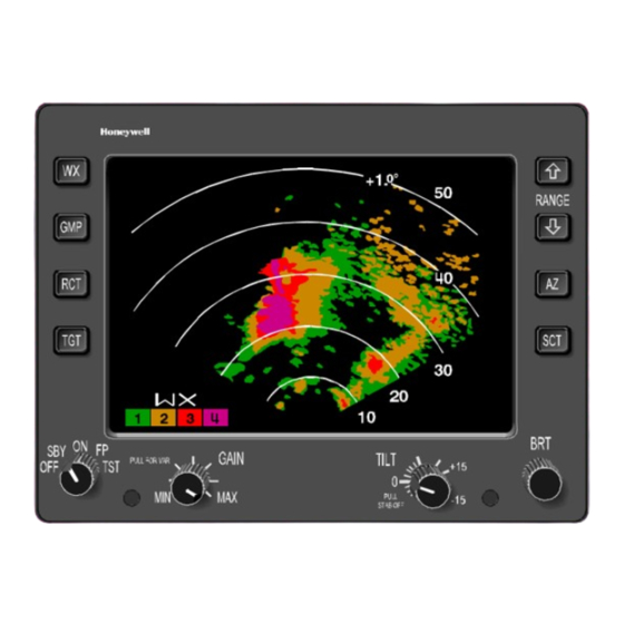
660 Digital Weather Radar Display Figure 3–1 The controls and display features of the WI–650/660 Weather Radar Indicator are indexed and identified in figure 3–2. Brightness levels for all legends and controls on the indicator are controlled by the dimming bus for the aircraft panel. -
Page 25: Wi-650/660 Weather Radar Indicator Front Panel View
PRIMUS 660 Digital Weather Radar System WI–650/660 Weather Radar Indicator Front Panel View Figure 3–2 WX (WEATHER) The WX button is used to select the weather mode of operation. When WX is pushed, the system is fully operational and all internal parameters are set for enroute weather detection. - Page 26 PRIMUS 660 Digital Weather Radar System WARNING WEATHER TYPE TARGETS ARE NOT CALIBRATED WHEN THE RADAR IS IN THE GMAP MODE. BECAUSE OF THIS, DO NOT USE THE GMAP MODE FOR WEATHER DETECTION. As a constant reminder the GMP is selected, the alphanumerics are changed to green, the GMP legend is shown in the mode field, and the color scheme is changed to cyan, yellow, and magenta.
-
Page 27: Target Alert Characteristics
PRIMUS 660 Digital Weather Radar System TGT (TARGET) The TGT button is an alternate–action switch that enables and disables the radar target alert feature. Target alert is selectable in all but the 300–mile range. When selected, target alert monitors beyond the selected range and 7.5°... -
Page 28: Wi-650/660 Weather Radar Indicator Display Screen Features
DISPLAY AREA See figure 3–3 and the associated text that explains the alphanumeric display. AD–51771@ WI–650/660 Weather Radar Indicator Display Screen Features Figure 3–3 FUNCTION SWITCH A rotary switch is used to select the following functions: OFF– This position turns off the radar system. -
Page 29: Rainfall Rate Color Coding
PRIMUS 660 Digital Weather Radar System ON – Places the system in the operational mode selected by the WX or MAP (GMP) button. When WX is selected, the system is fully operational and all internal parameters are set for enroute weather detection. - Page 30 PRIMUS 660 Digital Weather Radar System The TGT alert mode can be used in the FP mode. With target alert on and the FP mode selected, the target alert armed annunciation (green TGT) is displayed. The RTA searches for a hazardous target from 5 to 55 miles and ±7.5°...
- Page 31 PRIMUS 660 Digital Weather Radar System GAIN The GAIN knob is a single–turn rotary control and push/pull switch that is used to control the receiver gain. Push in on the GAIN switch to enter the system into the preset calibrated gain mode. Calibrated gain is the normal mode and is used for weather avoidance.
- Page 32 PRIMUS 660 Digital Weather Radar System BRT (Brightness) or BRT/LSS (Lightning Sensor System) The BRT knob is a single–turn control that adjusts the brightness of the display. CW rotation increases display brightness and ccw rotation decreases brightness. An optional BRT/LSS four–position rotary switch selects the separate LSZ–850 Lightning Sensor System (LSS) operating modes and the...
-
Page 33: Wc-660 Weather Radar Controller Operation
660 Digital Weather Radar System WC–660 WEATHER RADAR CONTROLLER OPERATION The controls and display features of the WC–660 Weather Radar Controller are indexed and identified in figure 3–4. Brightness levels for all legends and controls on the indicator are controlled by the dimming bus for the aircraft panel. - Page 34 PRIMUS 660 Digital Weather Radar System RANGE The RANGE switches are two momentary contact buttons that are used to select the operating range of the radar (and LSS if installed). The system permits selection of ranges in WX mode from 5 to 300 NM full scale.
-
Page 35: Wc–660 Controller Target Alert Characteristics
PRIMUS 660 Digital Weather Radar System TGT (TARGET) The TGT switch is an alternate–action, button that enables and disables the radar target alert feature. Target alert is selectable in all but the 300–mile range. When selected, target alert monitors beyond the selected range and 7.5_ on each side of the aircraft heading. - Page 36 PRIMUS 660 Digital Weather Radar System TILT The TILT knob is a rotary control that is used to select the tilt angle of antenna beam with relation to the horizon. CW rotation tilts beam upward 0_ to 15_; ccw rotation tilts beam downward 0_ to –15_. The range between +5_ and –5_ is expanded for ease of setting.
-
Page 37: Rainfall Rate Color Coding
PRIMUS 660 Digital Weather Radar System RADAR This rotary switch is used to select one of the following functions. OFF – This position turns off the radar system. STBY (Standby) – This position places the radar system in standby; a ready state, with the antenna scan stopped, the transmitter inhibited, and the display memory erased. - Page 38 PRIMUS 660 Digital Weather Radar System As a constant reminder that GMAP is selected, the GMAP legend is displayed in the mode field, and the color scheme is changed to cyan, yellow, and magenta. Cyan represents the least reflective return, yellow is a moderate return, and magenta is a strong return.
- Page 39 PRIMUS 660 Digital Weather Radar System FSBY (FORCED STANDBY) FSBY is an automatic, nonselectable radar mode. As an installation option, the RTA can be wired to the weight–on–wheels (WOW) squat switch. When wired, the RTA is in the FSBY mode when the aircraft is on the ground.
- Page 40 PRIMUS 660 Digital Weather Radar System In GMAP mode, variable gain is used to reduce the level of strong returns from ground targets. Minimum gain is attained with the control at its full ccw position. Gain increases as the control is rotated in a cw direction from full ccw at full cw position, the gain is at maximum.
-
Page 41: Normal Operation
PRIMUS 660 Digital Weather Radar System Normal Operation PRELIMINARY CONTROL SETTINGS Table 4–1 gives the power–up procedure for the PRIMUS 660 Digital Weather Radar System. Step Procedure Verify that the system controls are in the positions described below before powering up the radar system. - Page 42 PRIMUS 660 Digital Weather Radar System Step Procedure When power is first applied, the radar is in WAIT for approximately 90 seconds to allow the magnetron to warm up. Power interruptions lasting less than 3 seconds result in a 6–second wait period.
-
Page 43: Efis Test Pattern (Typical) 120_ Scan Shown
PRIMUS 660 Digital Weather Radar System TGT OR VAR ANNUNCIATOR TGT: TARGET ALERT P660 WX – GREEN–SELECTED MODE WX RANGE – AMBER TGT DETECTED ANNUNCIATIONS RINGS VAR: VARIABLE GAIN (AMBER) (WHITE) STBY (GREEN) TEST (GREEN) WX (GREEN) RCT (GREEN) TGT ALERT ON:... -
Page 44: Standby
PRIMUS 660 Digital Weather Radar System NOTES: 1. Refer to the specific EFIS manual for a detailed description. 2. The example shown is for installations with TEXT FAULT disabled. Standby When Standby is selected, and the radar is not in dual control mode (refer to table 2–1, dual control mode truth table, for dual control... -
Page 45: Radar Mode - Ground Mapping
Excessive losses in the radome seriously affect radar calibration. One possible means of verification are signal returns from known targets. Honeywell recommends that the pilot report evidence of weak returns to ensure that radome performance is maintained at a level that does not affect radar calibration. -
Page 46: Test Mode
660 Digital Weather Radar System Test Mode The PRIMUS 660 Digital Weather Radar System has a self–test mode and a maintenance function. In the self–test (TST) mode a special test pattern is displayed as illustrated earlier in this section. The functions of this pattern are as follows: Color Bands –... -
Page 47: Radar Facts
Radar Facts RADAR OPERATION The PRIMUS 660 Digital Weather Radar works on an echo principle. The radar sends out short bursts of electromagnetic energy that travel through space as a radio wave. When the traveling wave of energy strikes a target, some of the energy reflects back to the radar receiver. -
Page 48: Figure
PRIMUS 660 Digital Weather Radar System AIRCRAFT HEADING +0.6 AD–12055–R2@ Positional Relationship of an Airplane and Storm Cells Ahead as Displayed on Indicator Figure 5–1 The drawing is laid out to simulate the face of the indicator with the semicircular range marks. To derive a clearer concept of the picture that the indicator presents, imagine that the storm is a loaf of sliced bread standing on end. -
Page 49: Antenna Beam Slicing Out Cross Section Of Storm
PRIMUS 660 Digital Weather Radar System THUNDERSTORM ANTENNA TRANSMITTER INDICATOR SWEEP ORIGIN THUNDERSTORM SCAN AD–17716–R2@ Antenna Beam Slicing Out Cross Section of Storm During Horizontal Scan Figure 5–2 Weather radar can occasionally detect other aircraft, but it is not designed for this purpose and should never be considered a collision–avoidance device. -
Page 50: Sea Returns
PRIMUS 660 Digital Weather Radar System When the antenna is tilted downward for ground mapping, two phenomena can occur that can confuse the pilot. The first is called ”The Great Plains Quadrant Effect” that is seen most often when flying over the great plains of central United States. -
Page 51: Tilt Management
PRIMUS 660 Digital Weather Radar System TILT MANAGEMENT The pilot can use tilt management techniques to minimize ground clutter when viewing weather targets. Assume the aircraft is flying over relatively smooth terrain that is equivalent to sea level in altitude. The pilot must make adjustments for the effects of mountainous terrain. -
Page 52: Radar Beam Illumination Low Altitude 12-Inch Radiator
PRIMUS 660 Digital Weather Radar System Radar Beam Illumination Low Altitude 12–Inch Radiator Figure 5–6 AD54258@ Radar Beam Illumination Low Altitude 18–Inch Radiator Figure 5–7 A28–1146–111 Radar Facts REV 2... - Page 53 PRIMUS 660 Digital Weather Radar System Tables 5–1 and 5–2 give the approximate tilt settings that the ground targets begin to be displayed on the image periphery for 12– and 18–inch radiators. The range that the ground targets can be observed is affected by the curvature of the earth, the distance from the aircraft to the horizon, and altitude above the ground.
- Page 54 PRIMUS 660 Digital Weather Radar System RANGE SCALE LINE OF (NM) SIGHT (NM) ALTITUDE (FEET) 40,000 –12 –4 –1 35,000 –10 –3 30,000 –8 –2 25,000 –6 –1 20,000 –4 15,000 –11 –2 10,000 –6 –0 5,000 –5 –1 4,000 –4...
- Page 55 PRIMUS 660 Digital Weather Radar System RANGE SCALE LINE OF (MILES) 100 200 SIGHT (MILES) ALTITUDE (FEET) 40,000 –13 –5 –2 –1 –11 –4 –1 35,000 –9 –3 –1 30,000 –7 –2 25,000 –5 –1 20,000 –12 –3 –1 15,000 10,000 –7...
-
Page 56: Ideal Tilt Angle
PRIMUS 660 Digital Weather Radar System Tilt management is often misunderstood. It is crucial to safe operation of airborne weather radar. If radar tilt angles are not properly managed, weather targets can be missed or underestimated. The upper levels of convective storms are the most dangerous because of the probability of violent windshears and large hail. -
Page 57: Convective Thunderstorms
PRIMUS 660 Digital Weather Radar System Convective thunderstorms become much less reflective above the freezing level. This reflectivity decreases gradually over the first 5000 to 10,000 feet above the freezing level, as shown in figure 5–10. FREEZING LEVEL AD–35696@ Convective Thunderstorms Figure 5–10... -
Page 58: Proper Tilt Technique
PRIMUS 660 Digital Weather Radar System Proper tilt management demands that tilt be changed continually when approaching hazardous weather so that ground targets are not painted by the radar beam, as shown in figure 5–12. FREEZING LEVEL AD–35698@ Proper Tilt Technique Figure 5–12... -
Page 59: Fast Developing Thunderstorm
PRIMUS 660 Digital Weather Radar System Under the right conditions, a dangerous thunder bumper can develop in 10 minutes, and can in fact spawn and mature under the radar beam as the aircraft approaches it, as shown in figure 5–14. -
Page 60: Antenna Size And Impact On Tilt Management
PRIMUS 660 Digital Weather Radar System The antenna size used on the aircraft alters the best tilt settings by about 1_. However, tilt management is the same for either size, as shown in figure 5–16. AD–46703@ Antenna Size and Impact on Tilt Management Figure 5–16... -
Page 61: Stabilization
PRIMUS 660 Digital Weather Radar System STABILIZATION The purpose of the stabilization system is to hold the elevation of the antenna beam relative to the earth’s surface constant at all azimuths, regardless of aircraft bank and pitch maneuvers. The stabilization system uses the aircraft attitude source as a reference. -
Page 62: Antenna Mounting Error
PRIMUS 660 Digital Weather Radar System A vertical gyroscope contains a gravity–sensitive element, a heavily dampened pendulous device that enables the gyro to erect itself to earth gravity at the rate of approximately 2_/min. The pendulous device is unable to differentiate between earth gravity and an acceleration force. -
Page 63: Symmetrical Ground Returns
PRIMUS 660 Digital Weather Radar System LEVEL FLIGHT STABILIZATION CHECK Check stabilization in level flight using the procedure in table 5–3. Step Procedure Trim the aircraft for straight and level flight in smooth, clear air over level terrain. Select the 50–mile range. - Page 64 PRIMUS 660 Digital Weather Radar System AD–17721–R2@ Ground Return Indicating Misalignment (Upper Right) Figure 5–19 AD–17722–R2@ Ground Return Indicating Misalignment (Upper Left) Figure 5–20 A28–1146–111 Radar Facts 5-18 REV 2...
-
Page 65: Wallowing (Wing Walk And Yaw) Error
PRIMUS 660 Digital Weather Radar System Wallowing (Wing Walk and Yaw) Error A condition where the greatest intensity of ground targets wanders around the screen over a period of several minutes should not be confused with antenna mounting error. This phenomenon is caused by the tendency for many aircraft to slowly wallow (roll and yaw axes movement) with a cycle time of several minutes. -
Page 66: Symmetrical Ground Returns – Good Roll Stabilization
PRIMUS 660 Digital Weather Radar System Symmetrical Ground Returns – Good Roll Stabilization Figure 5–21 AD–17721–R2@ Understabilization in a Right Turn Figure 5–22 A28–1146–111 Radar Facts 5-20 REV 2... -
Page 67: Overstabilization In A Right Turn
PRIMUS 660 Digital Weather Radar System AD–17722–R2@ Overstabilization in a Right Turn Figure 5–23 AD–17723–R2@ Roll Stabilization Inoperative in a Turn Figure 5–24 A28–1146–111 Radar Facts REV 2 5-21... -
Page 68: Pitch Gain Error
PRIMUS 660 Digital Weather Radar System Pitch Gain Error If the aircraft is in a pitch maneuver and you see ground returns that are not present in level flight, the pitch gain is most likely misadjusted. The procedure in table 5–5 and figures 5–25, 5–26, and 5–27 can help you identify this type of problem. -
Page 69: Understabilized In Pitch–Up
PRIMUS 660 Digital Weather Radar System GMAP AD–53797@ Understabilized in Pitch–Up Figure 5–26 GMAP AD–53798@ Overstabilized in Pitch–Up Figure 5–27 Refer to Section 7, In–Flight Adjustments, for adjustment procedures. A28–1146–111 Radar Facts REV 2 5-23... -
Page 70: Interpreting Weather Radar Images
PRIMUS 660 Digital Weather Radar System INTERPRETING WEATHER RADAR IMAGES From a weather standpoint, hail and turbulence are the principal obstacles to a safe and comfortable flight. Neither of these conditions is directly visible on radar. The radar shows only the rainfall patterns that these conditions are associated. - Page 71 PRIMUS 660 Digital Weather Radar System The following are some truths about weather and flying, as shown in figure 5–29. Turbulence results when two air masses at different temperatures and/or pressures meet. This meeting can form a thunderstorm. The thunderstorm produces rain.
-
Page 72: Radar And Visual Cloud Mass
PRIMUS 660 Digital Weather Radar System VISIBLE CLOUD MASS RAIN AREA (ONLY THIS IS VISIBLE ON RADAR) RED ZONE WITHIN RAIN AREA RED LEVEL* NAUTICAL MILES AD–12057–R3@ Radar and Visual Cloud Mass Figure 5–29 As masses of warm, moist air are hurled upward to meet the colder air above, the moisture condenses and builds into raindrops heavy enough to fall downward through the updraft. -
Page 73: Squall Line
PRIMUS 660 Digital Weather Radar System To find a safe and comfortable route through the precipitation area, study the radar image of the squall line while closing in on the thunderstorm area. In the example shown in figure 5–30, radar... -
Page 74: Weather Display Calibration
PRIMUS 660 Digital Weather Radar System WEATHER DISPLAY CALIBRATION Ground based Nexrad radars of the National Weather Service display rainfall levels in dBZ, a decibel scaling of an arbitrary reflectivity factor (Z). The formula for determining dBZ is: dBZ = 16 log R + 23, where R is the rainfall rate in millimeters per hour. -
Page 75: Display Levels Related To Dbz Levels (Typical)
PRIMUS 660 Digital Weather Radar System 300 NAUTICAL MILES MAXIMUM CALIBRATE MAXIMUM MAXIMUM D RANGE CALIBRATE CALIBRATE RAINFALL RAINFALL (NM) 10–IN D RANGE D RANGE DISPLAY RATE RATE AND 12–IN (NM) 18–IN (NM) 24–IN LEVEL MM/HR IN./HR FLAT–PLATE FLAT–PLATE FLAT–PLATE... -
Page 76: Variable Gain Control
VARIABLE GAIN CONTROL The PRIMUS 660 Digital Weather Radar variable gain control is a single turn rotary control and a push/pull switch that is used to control the radar’s receiver gain. With the switch pushed in, the system is in the preset, calibrated gain mode. -
Page 77: Rain Echo Attenuation Compensation Technique (React)
660 Digital Weather Radar System RAIN ECHO ATTENUATION COMPENSATION TECHNIQUE (REACT) Honeywell’s REACT feature has three separate, but related functions. Attenuation Compensation – As the radar energy travels through rainfall, the raindrops reflect a portion of the energy back toward the airplane. - Page 78 PRIMUS 660 Digital Weather Radar System The receiver gain is adjusted to maintain target calibration. Since there is a maximum limit to receiver gain, strong targets (high attenuation levels) cause the receiver to reach its maximum gain value in a short time/short range. Weak or no targets (low attenuation levels) cause the receiver to reach its maximum gain value in a longer time/longer range.
-
Page 79: React On And Off Indications
PRIMUS 660 Digital Weather Radar System AD–51778–R1@ With REACT Selected AD–54262@ Without REACT REACT ON and OFF Indications Figure 5–31 A28–1146–111 Radar Facts REV 2 5-33... -
Page 80: Shadowing
PRIMUS 660 Digital Weather Radar System Shadowing An operating technique similar to the REACT blue field is shadowing. To use the shadowing technique, tilt the antenna down until ground is being painted just in front of the storm cell(s). An area of no ground returns behind the storm cell has the appearance of a shadow behind the cell. -
Page 81: Target
PRIMUS 660 Digital Weather Radar System Although penetrating a storm with a red (level three) core appears to be an acceptable risk, it is not. At the lower end of the red zone, there is no chance of extreme turbulence, a slight chance of severe turbulence, and a 40% chance of moderate turbulence. -
Page 82: Hail Size Probability
PRIMUS 660 Digital Weather Radar System Turbulence levels are listed and described in table 5–8. REACTION INSIDE AIRCRAFT INTENSITY AIRCRAFT REACTION Turbulence that momentarily causes Occupants can feel a slight slight, erratic changes in altitude and/or strain against seat belts or LIGHT attitude (pitch, roll, yaw). -
Page 83: Spotting Hail
PRIMUS 660 Digital Weather Radar System 100% 1/4” HAIL 1/2” HAIL 3/4” AND LAGER HAIL LEVEL 2 LEVEL 3 LEVEL 4 YELLOW MAGENTA AD–15358–R1@ Hail Size Probability Figure 5–33 Spotting Hail As previously stated, dry hail is a poor reflector, and therefore generates deceptively weak or absent radar returns. -
Page 84: Rain Coming From Unseen Dry Hail
PRIMUS 660 Digital Weather Radar System Using a tilt setting that has the radar look into the area of maximum reflectivity (5000 to 20,000 ft) gives the strongest radar picture. However the tilt setting must not be left at this setting. Periodically, the pilot should look up and down from this setting to see the total picture of the weather in the flightpath. -
Page 85: Overshooting A Storm
PRIMUS 660 Digital Weather Radar System The more that is learned about radar, the more the pilot is an all–important part of the system. The proper use of controls is essential to gathering all pertinent weather data. The proper interpretation of that data (the displayed patterns) is equally important to safety and comfort. -
Page 86: Short– And Long–Blind Alley
PRIMUS 660 Digital Weather Radar System Another example of the pilot’s importance in helping the radar serve its safety/comfort purpose is shown in figure 5–37. This is the blind alley or box canyon situation. Pilots can find themselves in this situation if they habitually fly with the radar on the short range. -
Page 87: Azimuth Resolution
PRIMUS 660 Digital Weather Radar System Azimuth Resolution When two targets, such as storms, are closely adjacent at the same range, the radar displays them as a single target, as shown in figure 5–38. However, as the aircraft approaches the targets, they appear to separate. -
Page 88: Radome
PRIMUS 660 Digital Weather Radar System RADOME Ice or water on the radome does not generally cause radar failure, but it hampers operation. The radome is constructed of materials that pass the radar energy with little attenuation. Ice or water increases the attenuation making the radar appear to have less sensitivity. -
Page 89: Weather Avoidance
PRIMUS 660 Digital Weather Radar System WEATHER AVOIDANCE Figure 5–39 illustrates a typical weather display in WX mode. Recommended procedures when using the radar for weather avoidance are given in table 5–9. The procedures are given in bold face, explanations of the procedure follow in normal type face. - Page 90 PRIMUS 660 Digital Weather Radar System Step Procedure Any storm with reported tops at or greater than 20,000 feet must be avoided by 20 NM. WARNING DRY HAIL CAN BE PREVALENT AT HIGHER ALTITUDES WITHIN, NEAR, OR ABOVE STORM CELLS, AND SINCE ITS RADAR REFLECTIVITY IS POOR, IT can NOT BE DETECTED.
- Page 91 PRIMUS 660 Digital Weather Radar System Step Procedure Avoid all rapidly moving echoes by 20 miles. A single thunderstorm echo, a line of echoes, or a cluster of echoes moving 40 knots or more often contain severe weather. Although nearby, slower moving echoes can contain more intense aviation hazards, all rapidly moving echoes warrant close observation.
- Page 92 PRIMUS 660 Digital Weather Radar System Step Procedure 2. Disturbed Wind Flow. Sometimes thunderstorm (cont) updrafts block winds near the thunderstorm and act much like a rock in a shallow river bed. This pillar of updraft forces the winds outside the storm to flow around the storm instead of carrying it along.
-
Page 93: Configurations Of Individual Echoes (Northern Hemisphere)
PRIMUS 660 Digital Weather Radar System Step Procedure Never continue flight towards or into a radar shadow or the blue REACT field. WARNING STORMS SITUATED BEHIND INTERVENING RAINFALL CAN BE MORE SEVERE THAN DEPICTED ON THE DIS- PLAY. If the radar signal can penetrate a storm, the target displayed seems to cast a shadow with no visible returns. -
Page 94: Typical Hook Pattern
PRIMUS 660 Digital Weather Radar System AD–15560–R1@ Typical Hook Pattern Figure 5–40 The hooks are located at the right rear side of the thunderstorm echo’s direction of movement (usually the southwest quadrant). The hook is not the tornado echo! A small scale low pressure area is centered at the right rear side of the thunderstorm echo near its edge. -
Page 95: V–Notch Echo, Pendant Shape
PRIMUS 660 Digital Weather Radar System AVOID V–NOTCH BY 20 MILES A large isolated echo sometimes has the configuration that is shown in figure 5–41. This echo is called V–notch or flying eagle although some imagination may be needed by the reader to see the eagle. -
Page 96: The Classic Pendant Shape
PRIMUS 660 Digital Weather Radar System AVOID PENDANT BY 20 MILES The pendant shape shown in figure 5–42, represents one of the most severe storms – the supercell. One study concluded that, in supercells: The average maximum size of hail is over 2 inches (5.3 cm) The average width of the hail swath is over 12.5 miles (20.2 km) -
Page 97: Rain Gradients
PRIMUS 660 Digital Weather Radar System AVOID STEEP RAIN GRADIENTS BY 20 MILES Figure 5–43 shows steep rain gradients. Refer to the paragraph, Interpreting Weather Radar Images, in this section, for a detailed explanation of weather images. AD–51781–R1@ Rain Gradients Figure 5–43... -
Page 98: Line Configurations
PRIMUS 660 Digital Weather Radar System AD–22161–R1@ Crescent Shape Figure 5–44 Line Configurations AVOID THUNDERSTORM ECHOES AT THE SOUTH END OF A LINE OR AT A BREAK IN A LINE BY 20 MILES The echo at the south end of a line of echoes is often severe and so too is the storm on the north side of a break in line. -
Page 99: Line Echo Wave Pattern (Lewp)
PRIMUS 660 Digital Weather Radar System AVOID LINE ECHO WAVE PATTERNS (LEWP) BY 20 MILES One portion of a line can accelerate and cause the line to assume a wave–like configuration. Figure 5–45 is an example of an LEWP. The most severe weather is likely at S. LEWPs form solid or nearly solid lines that are dangerous to aircraft operations and disruptive to normal air traffic flow. -
Page 100: Bow–Shaped Line Of Thunderstorms
PRIMUS 660 Digital Weather Radar System AVOID BOW–SHAPED LINE OF ECHOES BY 20 MILES Sometimes a fast moving, broken to solid thunderstorm line becomes bow–shaped, as shown in figure 5–46. Severe weather is most likely along the bulge and at the north end, but severe weather can occur at any point along the line. -
Page 101: Additional Hazards
PRIMUS 660 Digital Weather Radar System Additional Hazards TURBULENCE VERSUS DISTANCE FROM STORM CORE The stronger the return, the further the turbulence is encountered from the storm core at any altitude. Severe turbulence is often found in the tenuous anvil cloud 15 to 20 miles downwind from a severe storm core. -
Page 102: Ground Mapping
PRIMUS 660 Digital Weather Radar System GROUND MAPPING Ground mapping operation is selected with the GMAP button. An example of ground map display is shown in figure 5–47. Turn the TILT control down until the desired amount of terrain is displayed. The degree of down–tilt depends upon the type of terrain, aircraft altitude,... - Page 103 PRIMUS 660 Digital Weather Radar System RANGE SCALE LINE OF (NM) SIGHT (NM) ALTITUDE (FEET) 40,000 –12 –8 –11 –8 35,000 –10 –7 30,000 –13 –9 –7 25,000 –11 –8 –6 20,000 –10 –7 15,000 –6 –13 –8 –6 –5...
- Page 104 PRIMUS 660 Digital Weather Radar System RANGE SCALE LINE OF (MILES) 100 200 SIGHT (MILES) ALTITUDE (FEET) 40,000 –11 –7 –6 –10 –7 –5 35,000 –9 –6 –5 30,000 –8 –6 25,000 –7 –5 20,000 –8 –6 15,000 –5 10,000 –12...
-
Page 105: Maximum Permissible Exposure Level
Radio Frequency Electronic Fields 3kHz to 300 GHz (IEEE C95.1–1991), recommends an exposure level of no more than 6 mW/cm Honeywell recommends that operators follow the 6 mW/cm standard. Figure 6–1 shows MPEL for both exposure levels. MPEL Boundary Figure 6–1... -
Page 106: In-Flight Adjustments
In–Flight Adjustments PITCH AND ROLL TRIM ADJUSTMENTS The PRIMUS 660 is delivered from the Honeywell factory or repair facility adjusted for correct pitch and roll stabilization and should be ready for use. However, due to the tolerances of some vertical... - Page 107 PRIMUS 660 Digital Weather Radar System NOTES: 1. Depending on the installation, not all of the adjustments shown in table 7–1 are available. If STAB TRIM ENABLE programming pin is open, only the roll offset adjustment is available. If STAB TRIM ENABLE programming pin is grounded, all four adjustments are available.
-
Page 108: Level Fight Stabilization Check
PRIMUS 660 Digital Weather Radar System Level Fight Stabilization Check Follow the procedure in table 7–2 to determine if you need to perform the roll offset adjustment. Step Procedure Trim the aircraft for straight and level flight in smooth, clear air over level terrain at an altitude of at least 10,000 feet AGL. -
Page 109: Ground Return Indicating Misalignment (Right)
PRIMUS 660 Digital Weather Radar System Symmetrical Ground Returns Figure 7–1 AD–17721–R2@ Ground Return Indicating Misalignment (Right) Figure 7–2 A28–1146–111 In–Flight Adjustments REV 2... -
Page 110: Roll Offset Adjustment
ROLL OFFSET ADJUSTMENT You can make an in–flight adjustment when level flight stabilization errors are detected. This procedure is done by either the WC–660 Weather Radar Controller or the WI–650/660 Weather Radar Indicator. During this procedure, described in table 7–3, the GAIN control acts as roll offset control. - Page 111 PRIMUS 660 Digital Weather Radar System Step Procedure Adjust the tilt down until a solid band of ground returns are shown on the screen. Then adjust the tilt until the green region of the ground returns start at about 40 NM.
-
Page 112: Roll Offset Adjustment Display – Initial
PRIMUS 660 Digital Weather Radar System AD–51776@ Roll Offset Adjustment Display – Initial Figure 7–4 AD–51777–R1@ Roll Offset Adjustment Display – Final Figure 7–5 A28–1146–111 In–Flight Adjustments REV 2... -
Page 113: Pitch Offset Adjustment
PRIMUS 660 Digital Weather Radar System PITCH OFFSET ADJUSTMENT This in–flight adjustment is made in straight and level flight when the ground returns do not follow the contours of the radar display range arcs. The procedure is listed in table 7–4. -
Page 114: Roll Stabilization Check
PRIMUS 660 Digital Weather Radar System ROLL STABILIZATION CHECK Once proper operation in level flight has been established, you can verify correct roll stabilization using the procedures in table 7–5. Step Procedure Trim the aircraft for straight and level flight in smooth, clear air over level terrain at an altitude of at least 10,000 feet AGL. -
Page 115: Understabilization In A Right Roll
PRIMUS 660 Digital Weather Radar System Symmetrical Ground Returns, Level Flight and Good Roll Stabilization Figure 7–6 AD–17721–R2@ Understabilization in a Right Roll Figure 7–7 A28–1146–111 In–Flight Adjustments 7-10 REV 2... -
Page 116: Roll Gain Adjustment
PRIMUS 660 Digital Weather Radar System AD–17722–R2@ Overstabilization in a Right Roll Figure 7–8 ROLL GAIN ADJUSTMENT This in–flight adjustment is made in a bank when the ground returns do not remain symmetrical during turns. The procedure is listed in table 7–6. -
Page 117: Pitch Stabilization Check
PRIMUS 660 Digital Weather Radar System Step Procedure From the roll offset entry menu, push the STAB (STB) button twice more to bring up the roll gain entry menu. To change the roll gain value, pull out the GAIN knob and rotate it. -
Page 118: Level Flight And Good Pitch Stabilization
PRIMUS 660 Digital Weather Radar System Step Procedure If the display of ground returns goes out in range, the pitch is understabilized. See figure 7–10. If the display of ground returns comes in closer in range, the pitch is overstabilized. See figure 7–11. -
Page 119: Understabilized In Pitch Up
PRIMUS 660 Digital Weather Radar System AD–53802@ Understabilized in Pitch Up Figure 7–10 Overstabilized in Pitch Up Figure 7–11 A28–1146–111 In–Flight Adjustments 7-14 REV 2... -
Page 120: Pitch Gain Adjustment
PRIMUS 660 Digital Weather Radar System PITCH GAIN ADJUSTMENT This in–flight adjustment is made in a bank when the ground returns do not follow the contours of the range arcs during turns. The procedure is listed in table 7–8. Step Procedure If two controllers are installed, one must be turned off. -
Page 121: In-Flight Troubleshooting
(one at a time) on the indicator or EFIS display. The PRIMUS 660 also contains a feature called “Pilot Event Marker” that enables the pilot to record a full set of BITE parameters at any time, typically if the radar seems to be malfunctioning. -
Page 122: Test Mode With Text Faults Enabled
PRIMUS 660 Digital Weather Radar System TEST MODE WITH TEXT FAULTS ENABLED When airborne, if the radar is switched to TEST mode, any current faults are displayed. When on the ground (weight on wheels active) and the radar is switched to TEST mode, any current faults are displayed, followed by up to 32 faults from the last 10 power on cycles. - Page 123 PRIMUS 660 Digital Weather Radar System FAULT DISPLAY PILOT MESSAGE MESSAGE DIVIDER FIELD LINE FAULT CODE/ MAINTENANCE POWER ON MESSAGE COUNT FAULT TRANSMIT ON/OFF NAME TEST STRAP CODE AD–46709@ WEATHER INDICATOR Fault Annunciation on Weather Indicator With TEXT FAULT Fields Figure 8–1...
-
Page 124: Pilot Event Marker
PRIMUS 660 Digital Weather Radar System Radar Indication With Text Fault Enabled (On Ground) Figure 8–3 PILOT EVENT MARKER At any time a full set of BITE parameters can be recorded by going in and out of variable gain four times (pull GAIN knob for VAR, push for preset, pull for VAR, and push for preset) within three seconds. -
Page 125: Fault Code And Text Fault Relationships
PRIMUS 660 Digital Weather Radar System FAULT CODE AND TEXT FAULT RELATIONSHIPS Table 8–2 lists the relationship between: Fault codes (FC) Pilot/Maintenance (MAINT) Messages Fault Name/type/description/cross reference (XREF). PILOT LINE XREF FAULT DESCRIPTION FAULT NAME FAULT TYPE MAINT 4808 Startup Code CRC... - Page 126 PRIMUS 660 Digital Weather Radar System PILOT LINE XREF FAULT DESCRIPTION FAULT NAME FAULT TYPE MAINT 4813 Timing FPGA RAM 4814 Timing FPGA REG FPGA RADAR PULL POWER ON 4815 IO FPGA RAM FAIL FAIL 4828 FPGA Download 4906 IO FPGA REG...
- Page 127 PRIMUS 660 Digital Weather Radar System PILOT LINE XREF FAULT DESCRIPTION FAULT NAME FAULT TYPE MAINT 4840 AGC Limiting PICTURE CONTINUOUS UNCAL PULL 4927 AGC RX DAC Monitor RADAR POWER ON FAIL 4928 AGC TX DAC Monitor 4841 Selftest OSC Failure...
-
Page 128: Pilot Messages
PRIMUS 660 Digital Weather Radar System Table 8–3 describes the pilot messages. Pilot MSG Description RADAR FAIL The radar is currently inoperable and should not be relied upon. It needs to be replaced or repaired at the next opportunity. RADAR CAUTION A failure has been detected that can compromise the calibration accuracy of the radar. -
Page 129: Honeywell Product Support
All articles are returned to Reconditioned Specifications limits when they are processed through a Honeywell repair facility. All articles are inspected by quality control personnel to verify proper workmanship and conformity to Type Design and to certify that the article meets all controlling documentation. - Page 130 PRIMUS 660 Digital Weather Radar System The Honeywell Support Centers listed below will assist with processing exchange/rental orders. 24–HOUR EXCHANGE/RENTAL SUPPORT CENTERS U.S.A. – DALLAS CANADA – OTTAWA 800–872–7739 800–267–9947 972–402–4300 613–728–4681 ENGLAND – BASINGSTOKE AUSTRALIA – TULLAMARINE 44–1256–72–2200 61–3–9330–1411 FRANCE –...
- Page 131 PRIMUS 660 Digital Weather Radar System CUSTOMER SUPPORT CENTERS – NORTH AMERICA ( CONT Miami Support Center Honeywell Inc. Commercial Aviation Systems 7620 N.W. 25th Street Bldg. C Unit 6 MIAMI, FL 33122 TEL: 305–436–8722 FAX: 305–436–8532 CUSTOMER SUPPORT CENTERS – REST OF THE WORLD...
-
Page 132: Publication Ordering Information
PRIMUS 660 Digital Weather Radar System PUBLICATION ORDERING INFORMATION Additional copies of this manual can be obtained by contacting: Honeywell Inc. P.O. Box 29000 Business and Commuter Aviation Systems Phoenix, Arizona 85038–9000 Attention: Publication Distribution, Dept. M/S V19A1 Telephone No.: (602) 436–6900... -
Page 133: 10. Abbreviations
PRIMUS 660 Digital Weather Radar System 10. Abbreviations Abbreviations used in this manual are defined as follows: TERMS DEFINITION Advisory Circular Air Data Computer Automatic Flight Control Automatic Gain Control Above Ground Level AHRS Attitude Heading Reference System Antenna Position Indicator... - Page 134 PRIMUS 660 Digital Weather Radar System TERMS DEFINITION Feet, Foot GMAP, GMP Ground Mapping Global Positioning System GSPD Groundspeed HOLDA Hold Acknowledge HVPS High Voltage Power Supply INHIB Inhibit Interrupt Input/Output Inoperative Inertial Reference System Knot(s) LEWP Line Echo Wave Patterns...
- Page 135 PRIMUS 660 Digital Weather Radar System TERMS DEFINITION Register Receiver Transmitter Antenna Receiver SBY, STBY Standby Serial Control Interface SCT, SECT Scan Sector Slave SPEX Spares Exchange STAB, STB Stabilization Sensitivity Time Control TCAS Traffic Alert and Crew Alerting System...
-
Page 136: Subject: Recommended Radiation Safety Precautions
PRIMUS 660 Digital Weather Radar System Appendix A Federal Aviation Administration (FAA) Advisory Circulars NOTE: This section contains a word–for–word transcription of the contents of the following FAA advisory circulars: AC 20–68B AC 00–24B. SUBJECT: RECOMMENDED RADIATION SAFETY PRECAUTIONS GROUND... -
Page 137: Precautions
PRIMUS 660 Digital Weather Radar System Precautions Management and supervisory personnel should establish procedures for advising personnel of dangers from operating airborne weather radars on the ground. Precautionary signs should be displayed in affected areas to alert personnel of ground testing. -
Page 138: Subject: Thunderstorms
PRIMUS 660 Digital Weather Radar System COMBUSTIBLE MATERIALS To prevent possible fuel ignition, an insulated airborne weather radar should not be operated while an aircraft is being refueled or defueled. M.C. Beard Director of Airworthiness. SUBJECT: THUNDERSTORMS Purpose This advisory circular describes the hazards of thunderstorms to aviation and offers guidance to help prevent accidents caused by thunderstorms. -
Page 139: Hazards
PRIMUS 660 Digital Weather Radar System Hazards A thunderstorm packs just about every weather hazard known to aviation into one vicious bundle. Although the hazards occur in numerous combinations, let us look at the most hazardous combination of thunderstorm, the squall line, then we will examine the hazards individually. - Page 140 PRIMUS 660 Digital Weather Radar System TURBULENCE Potentially hazardous turbulence is present in all thunderstorms, and a severe thunderstorm can destroy an aircraft. Strongest turbulence within the cloud occurs with shear between updrafts and downdrafts. Outside the cloud, shear turbulence has been encountered several thousand feet above and 20 miles laterally from a severe thunderstorm.
- Page 141 PRIMUS 660 Digital Weather Radar System COLD Schematic Cross Section of a Thunderstorm Figure A–1 HAIL Hail competes with turbulence as the greatest thunderstorm hazard to aircraft. Supercooled drops above the freezing level begin to freeze. Once a drop has frozen, other drops latch on and freeze to it, so the hailstone grows –...
- Page 142 PRIMUS 660 Digital Weather Radar System LOW CEILING AND VISIBILITY Generally, visibility is near zero within a thunderstorm cloud. Ceiling and visibility may also be restricted in precipitation and dust between the cloud base and the ground. The restrictions create the same problem as all ceiling and visibility restrictions;...
- Page 143 PRIMUS 660 Digital Weather Radar System The National Weather Service (NWS) radar observer is able to objectively determine storm intensity levels with VIP equipment. These radar echo intensity levels are on a scale of one to six. If the maximum VIP levels are 1 ”weak”...
- Page 144 PRIMUS 660 Digital Weather Radar System Don’t attempt to fly under a thunderstorm even if you can see through to the other side. Turbulence and wind shear under the storm could be disastrous. Don’t fly without airborne radar into a cloud mass containing scattered embedded thunderstorms.
-
Page 145: National Severe Storms Laboratory (Nssl)
PRIMUS 660 Digital Weather Radar System If using airborne radar, tilt the antenna up and down occasionally. This will permit you to detect other thunderstorm activity at altitudes other than the one being flown. Following are some do’s and don’ts during thunderstorm penetration. - Page 146 PRIMUS 660 Digital Weather Radar System TURBULENCE AND ECHO INTENSITY ON NWS RADAR (WSR–57) The frequency and severity of turbulence increases with radar reflectivity, a measure of the intensity of echoes from storm targets at a standard range. Derived gust velocities exceeding 2,100 feet per minute (classified as severe turbulence) are commonly encountered in level 3 storms.
- Page 147 PRIMUS 660 Digital Weather Radar System TURBULENCE ABOVE STORM TOPS Flight data shows a relationship between turbulence above storm tops and the airspeed of upper tropospheric winds. WHEN THE WINDS AT STORM TOP EXCEED 100 KNOTS, THERE ARE TIMES WHEN SIGNIFICANT TURBULENCE MAY BE EXPERIENCED AS MUCH AS 10,000 FEET ABOVE THE CLOUD TOPS.
- Page 148 PRIMUS 660 Digital Weather Radar System MODIFICATION OF CRITERIA WHEN SEVERE STORMS AND RAPID DEVELOPMENT ARE EVIDENT During severe storm situations, radar echo intensities may grow by a factor of ten each minute, and cloud tops by 7,000 feet per minute.
-
Page 149: B Enhanced Ground-Proximity Warning System (Egpws
PRIMUS 660 Digital Weather Radar System Appendix B Enhanced Ground–Proximity Warning System (EGPWS) The AlliedSignal Mark VII EGPWS combines information from aircraft navigation equipment (i.e. flight management system (FMS), inertial reference system (IRS), global positioning system (GPS), radio altimeter) with a stored terrain data base that alerts the pilot to potentially dangerous ground proximity. - Page 150 PRIMUS 660 Digital Weather Radar System PUSH BUTTON CONTROLS The following remotely mounted push buttons control the EGPWS display: INHIB (Inhibit) Button – When active, the push on/push off INHIB button prevents terrain data from being displayed on the radar indicator.
-
Page 151: Related Egpws System Operation
PRIMUS 660 Digital Weather Radar System Related EGPWS System Operation Some installations may have a DATA–NAV (navigation display, and/or checklist), lightning sensor system (LSS), and/or traffic alert and crew alerting system (TCAS) that already share the radar indicator’s display by way of the Universal Digital Interface (UDI) connector. These systems have priority for access to the radar display screen. -
Page 152: Egpws Display
PRIMUS 660 Digital Weather Radar System EGPWS Display The EGPWS displays is shown as variable dot patterns in green, yellow, or red. The density and color is a function of how close the terrain is relative to the aircraft altitude above ground level (AGL), refer to table B–1. -
Page 153: Egpws Display
PRIMUS 660 Digital Weather Radar System Figure B–1 shows the EGPWS over KPHX airport at 2000 feet mean sea level heading north. The terrain shows the mountains to the north of Phoenix. AD–62964@ EHSI Display Over KPHX Airport With the EGPWS Display Figure B–1... -
Page 154: Egpws Test
PRIMUS 660 Digital Weather Radar System EGPWS Test When the EGPWS is selected for display, it can be tested. Push the remote mounted EGPWS TEST button to display the test format shown in figure B–2. AD–63056@ EGPWS Test Display Figure B–2 A28–1146–111... -
Page 155: Index
PRIMUS 660 Digital Weather Radar System Index Abbreviations, 10-1 Effect on altimeters, A–7 Accelerative Error, 5-15 Enhanced ground–proximity warning Additional hazards, 5-55 system (EGPWS), B–1 turbulence versus distance from annunciators, B–2 storm core, 5-55 FAIL, B–2 turbulence versus distance from INHIB, B–2... - Page 156 PRIMUS 660 Digital Weather Radar System Index (cont) Hail size probability, 5-36 Honeywell product support, 9-1 Fault code and text fault customer support centers, 9-2, relationships, 8-5 North America, 9-2 pilot messages, 8-8 Rest of the World, 9-3 Federal Aviation Administration...
- Page 157 PRIMUS 660 Digital Weather Radar System Index (cont) relationship between turbulence and reflectivity, A–10 turbulence above storm tops, Level flight stabilization check, 5-17, A–11 turbulence and echo intensity on stabilization in straight and level NWS radar (WSR–57), A–11 flight check...
- Page 158 PRIMUS 660 Digital Weather Radar System Index (cont) weather radar controller pitch stabilization check, 5-22 operation, WC–660 (cont) Pitch offset adjustment, 7-8 RCT (rain echo attenuation adjustment procedure, 7-8 compensation technique Pitch stabilization check, 7-12 (REACT)), 3-11 check procedure, 7-12...
- Page 159 PRIMUS 660 Digital Weather Radar System Index (cont) azimuth resolution, 5-41 related reading material, A–1 hail size probability, 5-36 Reflectivity, A–10 shadowing, 5-34 relationship between turbulence spotting hail, 5-37 and reflectivity, A–10 turbulence probability, 5-34 Relationship between turbulence stabilization, 5-15 and altitude, A–10...
- Page 160 PRIMUS 660 Digital Weather Radar System Index (cont) System configurations, 2-1 relationship between dual configuration, 2-1 turbulence and altitude, dual control mode truth table, 2-3 A–10 equipment list, 2-4 relationship between cockpit mounted options, 2-4 turbulence and reflectivity, remote mounted, 2-4 A–10...
- Page 161 PRIMUS 660 Digital Weather Radar System Index (cont) versus distance from storm core, avoid hook echoes by 20 5-55 miles, 5-47 versus distance from storm edge, avoid pendant by 20 miles, 5-55 5-50 visual appearance of storm and avoid steep rain gradients by...
- Page 162 PRIMUS 660 Digital Weather Radar System Index (cont) Weather radar controller operation, WC–660 (cont) SLV (slave) (dual installations only), 3-13 STAB (stabilization), 3-11 target alert characteristics, 3-12 TGT (target), 3-12 TILT, 3-13 Weather radar indicator operation, WI–650/660, 3-1 AZ (azimuth), 3-9...